brake fluid JEEP GRAND CHEROKEE 2002 WJ / 2.G User Guide
[x] Cancel search | Manufacturer: JEEP, Model Year: 2002, Model line: GRAND CHEROKEE, Model: JEEP GRAND CHEROKEE 2002 WJ / 2.GPages: 2199, PDF Size: 76.01 MB
Page 182 of 2199

SPECIAL TOOLS
BASE BRAKESBRAKE FLUID LEVEL SWITCH
REMOVAL
(1) Remove the wire connector from the fluid level
sensor.
(2) From the same side of the master cylinder res-
ervoir release the sensor locking taps with a small
screw driver.
(3) Pull the sensor out of the reservoir from the
connector side of the sensor.
INSTALLATION
(1) Install the sensor with a new o-ring into the
reservoir until the locking tabs are engaged.
(2) Install the wire connector to the fluid level sen-
sor.
RED BRAKE WARN INDICATOR
SWITCH
DESCRIPTION
A red warning lamp is used for the service brake
portion of the hydraulic system. The lamp is located
in the instrument cluster.
OPERATION
The lamp is turned on momentarily when the igni-
tion switch is turn to the on position. This is a self
test to verify the lamp is operational.
The red warning light alerts the driver if the fluid
level is low or the parking brakes are applied. A red
warning lamp with an amber warning lamp may
indicate a electronic brake distribution fault.
DIAGNOSIS AND TESTING - RED BRAKE
WARNING LAMP
The red warning lamp illuminates when the park-
ing brake is applied or when the fluid level in the
master cylinder is low. It will also illuminate at start
up as part of a bulb check.
If the light comes on, first verify that the parking
brakes are fully released. Then check pedal action
and fluid level. If a problem is confirmed, inspect the
brake hydraulic system for leaks.
A red warning lamp with a amber warning lamp
may indicate a electronic brake distribution fault.
Installer Caliper Dust Boot 8280
Handle C-4171
Adapter Pressure Bleeder 6921
WJBRAKES - BASE 5 - 7
BRAKES - BASE (Continued)
Page 185 of 2199

BRAKE PADS / SHOES
DESCRIPTION
DESCRIPTION - FRONT DISC BRAKE SHOES
The calipers are twin piston type. The calipers are
free to slide laterally on the anchor, this allows con-
tinuous compensation for lining wear.
DESCRIPTION - REAR DISC BRAKE SHOES
The rear disc brakes consist of single piston float-
ing-type calipers and solid rotors. The rear caliper is
mounted on an anchor attached to an adapter
attached the rear axle tube flange. The anchors are
secured to the adapters with mounting bolts. The
disc brake rotor splash shield is part of the adaptor.
The disc brake rotor has a built in brake drum used
for the parking brakes (Fig. 6). The parking brake
shoes are mounted to the adaptor.
OPERATION
OPERATION - FRONT DISC BRAKE SHOES
When the brakes are applied fluid pressure is
exerted against the caliper pistons. The fluid pres-
sure is exerted equally and in all directions. This
means pressure exerted against the caliper pistons
and within the caliper bores will be equal (Fig. 7).
Fluid pressure applied to the pistons is transmit-
ted directly to the inboard brake shoe. This forces the
shoe lining against the inner surface of the disc
brake rotor. At the same time, fluid pressure within
the piston bores forces the caliper to slide inward on
the slide pins. This action brings the outboard brake
shoe lining into contact with the outer surface of the
disc brake rotor.
Fluid pressure acting simultaneously on the pis-
tons and caliper to produces a strong clamping
action. When sufficient force is applied, friction will
stop the rotors from turning and bring the vehicle to
a stop.Application and release of the brake pedal gener-
ates only a very slight movement of the caliper and
pistons. Upon release of the pedal, the caliper and
pistons return to a rest position. The brake shoes do
not retract an appreciable distance from the rotor. In
fact, clearance is usually at, or close to zero. The rea-
sons for this are to keep road debris from getting
between the rotor and lining and in wiping the rotor
surface clear each revolution.
The caliper piston seals control the amount of pis-
ton extension needed to compensate for normal lining
wear.
During brake application, the seals are deflected
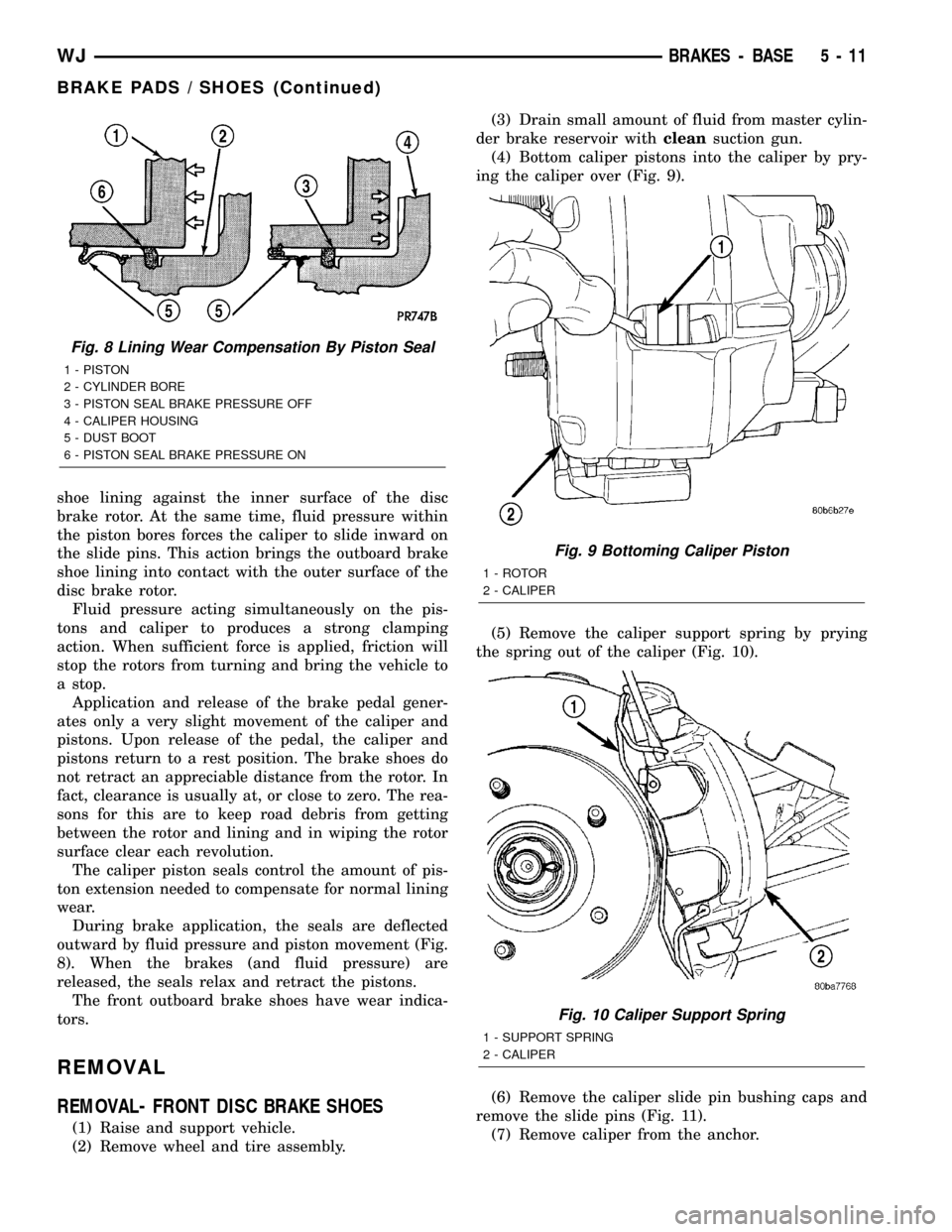
outward by fluid pressure and piston movement (Fig.
8). When the brakes (and fluid pressure) are
released, the seals relax and retract the pistons.
The front outboard brake shoes have wear indica-
tors.
OPERATION - REAR DISC BRAKE SHOES
When the brakes are applied fluid pressure is
exerted against the caliper pistons. The fluid pres-
sure is exerted equally and in all directions. This
means pressure exerted against the caliper pistons
and within the caliper bores will be equal (Fig. 7).
Fluid pressure applied to the pistons is transmit-
ted directly to the inboard brake shoe. This forces the
Fig. 6 Rear Disc Brake Rotor
1 - PARKING BRAKE DRUM SURFACE
2 - REAR DISC BRAKE ROTOR
Fig. 7 Brake Caliper Operation
1 - CALIPER
2 - PISTON
3 - PISTON BORE
4 - SEAL
5 - INBOARD SHOE
6 - OUTBOARD SHOE
5 - 10 BRAKES - BASEWJ
Page 186 of 2199

shoe lining against the inner surface of the disc
brake rotor. At the same time, fluid pressure within
the piston bores forces the caliper to slide inward on
the slide pins. This action brings the outboard brake
shoe lining into contact with the outer surface of the
disc brake rotor.
Fluid pressure acting simultaneously on the pis-
tons and caliper to produces a strong clamping
action. When sufficient force is applied, friction will
stop the rotors from turning and bring the vehicle to
a stop.
Application and release of the brake pedal gener-
ates only a very slight movement of the caliper and
pistons. Upon release of the pedal, the caliper and
pistons return to a rest position. The brake shoes do
not retract an appreciable distance from the rotor. In
fact, clearance is usually at, or close to zero. The rea-
sons for this are to keep road debris from getting
between the rotor and lining and in wiping the rotor
surface clear each revolution.
The caliper piston seals control the amount of pis-
ton extension needed to compensate for normal lining
wear.
During brake application, the seals are deflected
outward by fluid pressure and piston movement (Fig.
8). When the brakes (and fluid pressure) are
released, the seals relax and retract the pistons.
The front outboard brake shoes have wear indica-
tors.
REMOVAL
REMOVAL- FRONT DISC BRAKE SHOES
(1) Raise and support vehicle.
(2) Remove wheel and tire assembly.(3) Drain small amount of fluid from master cylin-
der brake reservoir withcleansuction gun.
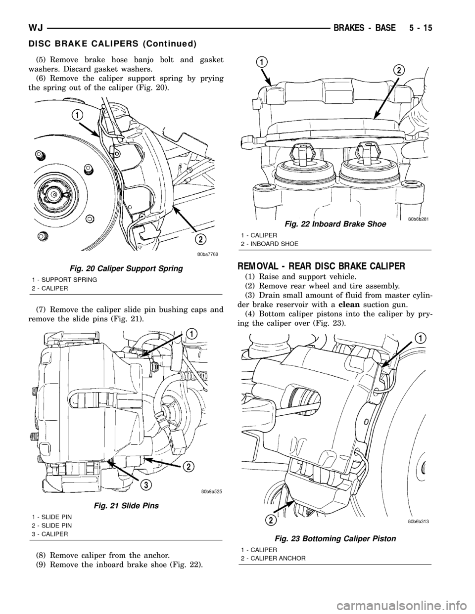
(4) Bottom caliper pistons into the caliper by pry-
ing the caliper over (Fig. 9).
(5) Remove the caliper support spring by prying
the spring out of the caliper (Fig. 10).
(6) Remove the caliper slide pin bushing caps and
remove the slide pins (Fig. 11).
(7) Remove caliper from the anchor.
Fig. 8 Lining Wear Compensation By Piston Seal
1 - PISTON
2 - CYLINDER BORE
3 - PISTON SEAL BRAKE PRESSURE OFF
4 - CALIPER HOUSING
5 - DUST BOOT
6 - PISTON SEAL BRAKE PRESSURE ON
Fig. 9 Bottoming Caliper Piston
1 - ROTOR
2 - CALIPER
Fig. 10 Caliper Support Spring
1 - SUPPORT SPRING
2 - CALIPER
WJBRAKES - BASE 5 - 11
BRAKE PADS / SHOES (Continued)
Page 187 of 2199

(8) Secure caliper to nearby suspension part with
wire.Do not allow brake hose to support caliper
weight.
(9) Remove the inboard brake shoe from the cali-
per (Fig. 12).
(10) Remove the outboard brake shoe (Fig. 13)
from the caliper anchor.REMOVAL - REAR DISC BRAKE SHOES
(1) Raise and support vehicle.
(2) Remove rear wheel and tire assembly.
(3) Drain small amount of fluid from master cylin-
der brake reservoir with acleansuction gun.
(4) Bottom caliper pistons into the caliper by pry-
ing the caliper over (Fig. 14).
Fig. 11 Caliper Slide
1 - SLIDE PIN
2 - SLIDE PIN
3 - CALIPER
Fig. 12 Inboard Brake Shoe
1 - CALIPER
2 - INBOARD SHOE
Fig. 13 Outboard Brake Shoe
1 - CALIPER ANCHOR
2 - OUTBOARD BRAKE SHOE
Fig. 14 Bottoming Caliper Piston
1 - CALIPER
2 - CALIPER ANCHOR
5 - 12 BRAKES - BASEWJ
BRAKE PADS / SHOES (Continued)
Page 189 of 2199

(8) Install wheel and tire assembly.
(9) Remove support and lower vehicle.
(10) Pump brake pedal until caliper pistons and
brake shoes are seated and a firm brake pedal is
obtained.
(11) Fill brake fluid.
INSTALLATION - REAR DISC BRAKE SHOES
(1) Install the inboard brake shoe onto the caliper
(Fig. 17).
(2) Install the outboard brake shoe onto the caliper
anchor (Fig. 18).
(3) Lubricate the slide pins and slide pin bushings
with Dow Corningtgrease G807 or the grease pro-
vided with the brake shoes.
(4) Install caliper on the anchor.
(5) Install the caliper slide pin and tighten to
29-41 N´m (21-30 ft. lbs.).
(6) Install the caliper slide pin bushing caps.
(7) Install the caliper support spring in the top
end of the caliper and under the anchor. Then installother end into the lower caliper hole. Hold the spring
into the caliper hole with your thumb while prying
the end of the spring out and down under the anchor
with a screw drive.
(8) Install wheel and tire assembly.
(9) Remove support and lower vehicle.
(10) Pump brake pedal until caliper piston and
brake shoes are seated and a firm brake pedal is
obtained.
(11) Fill brake fluid level if necessary.
DISC BRAKE CALIPERS
REMOVAL
REMOVAL - FRONT DISC BRAKE CALIPER
(1) Raise and support vehicle.
(2) Remove front wheel and tire assembly.
(3) Drain small amount of fluid from master cylin-
der brake reservoir withcleansuction gun.
(4) Bottom caliper pistons into the caliper by pry-
ing the caliper over (Fig. 19).
Fig. 18 Outboard Brake Shoe
1 - OUTBOARD BRAKE SHOE
2 - CALIPER ANCHOR
3 - ROTOR
Fig. 19 Bottoming Caliper Piston
1 - ROTOR
2 - CALIPER
5 - 14 BRAKES - BASEWJ
BRAKE PADS / SHOES (Continued)
Page 190 of 2199

(5) Remove brake hose banjo bolt and gasket
washers. Discard gasket washers.
(6) Remove the caliper support spring by prying
the spring out of the caliper (Fig. 20).
(7) Remove the caliper slide pin bushing caps and
remove the slide pins (Fig. 21).
(8) Remove caliper from the anchor.
(9) Remove the inboard brake shoe (Fig. 22).
REMOVAL - REAR DISC BRAKE CALIPER
(1) Raise and support vehicle.
(2) Remove rear wheel and tire assembly.
(3) Drain small amount of fluid from master cylin-
der brake reservoir with acleansuction gun.
(4) Bottom caliper pistons into the caliper by pry-
ing the caliper over (Fig. 23).
Fig. 20 Caliper Support Spring
1 - SUPPORT SPRING
2 - CALIPER
Fig. 21 Slide Pins
1 - SLIDE PIN
2 - SLIDE PIN
3 - CALIPER
Fig. 22 Inboard Brake Shoe
1 - CALIPER
2 - INBOARD SHOE
Fig. 23 Bottoming Caliper Piston
1 - CALIPER
2 - CALIPER ANCHOR
WJBRAKES - BASE 5 - 15
DISC BRAKE CALIPERS (Continued)
Page 192 of 2199

DISASSEMBLY
DISASSEMBLY - FRONT DISC BRAKE CALIPER
(1) Drain the brake fluid from caliper.
(2) C-clamp a block of wood over one piston (Fig.
27).
(3) Take another piece of wood and pad it with
one-inch thickness of shop towels. Place this piece in
the outboard shoe side of the caliper in front of the
other piston. This will cushion and protect caliper
piston during removal (Fig. 28).(4) To remove the caliper piston directshort
bursts of low pressure airwith a blow gun
through the caliper brake hose port. Use only enough
air pressure to ease the piston out.
CAUTION: Do not blow the piston out of the bore
with sustained air pressure. This could result in a
cracked piston.
WARNING: NEVER ATTEMPT TO CATCH THE PIS-
TON AS IT LEAVES THE BORE. THIS COULD
RESULT IN PERSONAL INJURY.
(5) Remove the C-clamp and block of wood from
the caliper and clamp it over the dust boot of the
first piston removed. This will seal the empty piston
bore.
(6) Move the padded piece of wood in front of the
other piston.
(7) Remove the second piston using the same pro-
cedure withshort bursts of low pressure air.
(8) Remove piston dust boots with a suitable pry
tool (Fig. 29)and discard.
Fig. 27 C-Clamp One Piston
1 - BLOCK OF WOOD
2 - C-CLAMP
3 - CALIPER
Fig. 28 Protect Caliper Piston
1 - CALIPER
2 - PADDED BLOCK OF WOOD
3 - C-CLAMP
Fig. 29 Piston Dust Boot Removal
1 - CALIPER
2 - PISTON DUST BOOT
WJBRAKES - BASE 5 - 17
DISC BRAKE CALIPERS (Continued)
Page 193 of 2199

(9) Remove piston seals from caliper (Fig. 30) and
discard.
CAUTION: Do not scratch piston bore while remov-
ing the seals.
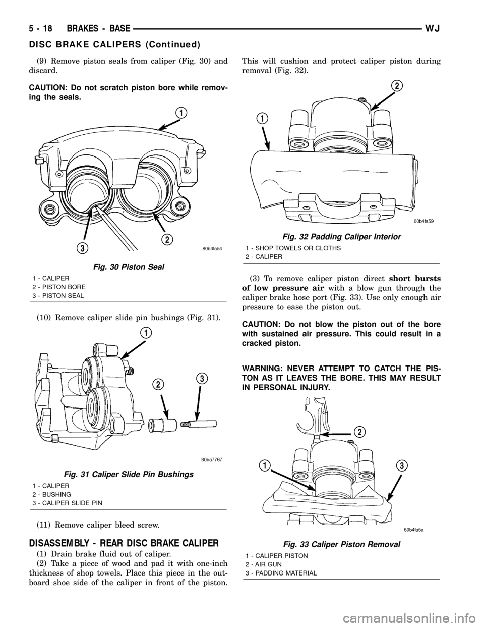
(10) Remove caliper slide pin bushings (Fig. 31).
(11) Remove caliper bleed screw.
DISASSEMBLY - REAR DISC BRAKE CALIPER
(1) Drain brake fluid out of caliper.
(2) Take a piece of wood and pad it with one-inch
thickness of shop towels. Place this piece in the out-
board shoe side of the caliper in front of the piston.This will cushion and protect caliper piston during
removal (Fig. 32).
(3) To remove caliper piston directshort bursts
of low pressure airwith a blow gun through the
caliper brake hose port (Fig. 33). Use only enough air
pressure to ease the piston out.
CAUTION: Do not blow the piston out of the bore
with sustained air pressure. This could result in a
cracked piston.
WARNING: NEVER ATTEMPT TO CATCH THE PIS-
TON AS IT LEAVES THE BORE. THIS MAY RESULT
IN PERSONAL INJURY.
Fig. 30 Piston Seal
1 - CALIPER
2 - PISTON BORE
3 - PISTON SEAL
Fig. 31 Caliper Slide Pin Bushings
1 - CALIPER
2 - BUSHING
3 - CALIPER SLIDE PIN
Fig. 32 Padding Caliper Interior
1 - SHOP TOWELS OR CLOTHS
2 - CALIPER
Fig. 33 Caliper Piston Removal
1 - CALIPER PISTON
2 - AIR GUN
3 - PADDING MATERIAL
5 - 18 BRAKES - BASEWJ
DISC BRAKE CALIPERS (Continued)
Page 194 of 2199

(4) Remove caliper piston dust boot with a suitable
pry tool (Fig. 34) and discard.
(5) Remove piston seal from the caliper (Fig.
35)and discard.
CAUTION: Do not scratch the piston bore while
removing the seal.
(6) Remove caliper slide pin bushings (Fig. 36).
(7) Remove caliper bleed screw.
CLEANING - DISC BRAKE CALIPER
Clean the caliper components with clean brake
fluid or brake clean only. Wipe the caliper and piston
dry with lint free towels or use low pressure com-
pressed air.
CAUTION: Do not use gasoline, kerosene, paint
thinner, or similar solvents. These products may
leave a residue that could damage the piston and
seal.
INSPECTION - DISC BRAKE CALIPER
The piston is made from a phenolic resin (plastic
material) and should be smooth and clean.
The piston must be replaced if cracked or scored.
Do not attempt to restore a scored piston surface by
sanding or polishing.
CAUTION: If the caliper piston is replaced, install
the same type of piston in the caliper. Never inter-
change phenolic resin and steel caliper pistons.
The pistons, seals, seal grooves, caliper bore and
piston tolerances are different.
The bore can belightlypolished with a brake
hone to remove very minor surface imperfections
(Fig. 37). The caliper should be replaced if the bore is
severely corroded, rusted, scored, or if polishing
would increase bore diameter more than 0.025 mm
(0.001 inch).
Fig. 34 Caliper Piston Dust
1 - PISTON DUST BOOT
2 - CALIPER
Fig. 35 Piston Seal Removal
1 - CALIPER
2 - PISTON BORE
3 - PISTON SEAL
Fig. 36 Slide Pin And Bushing
1 - BUSHING
2 - CALIPER SLIDE PIN
WJBRAKES - BASE 5 - 19
DISC BRAKE CALIPERS (Continued)
Page 195 of 2199

ASSEMBLY
ASSEMBLY - FRONT DISC BRAKE CALIPER
CAUTION: Dirt, oil, and solvents can damage cali-
per seals. Insure assembly area is clean and dry.
(1) Lubricate caliper pistons, piston seals and pis-
ton bores with clean brake fluid.
(2) Install new piston seals into seal groove with
finger (Fig. 38).
NOTE: Verify seal is fully seated and not twisted.(3) Install new dust boot on caliper piston and seat
boot lip into piston groove (Fig. 39).
(4) Stretch boot rearward to straighten boot folds,
then move boot forward until folds snap into place.
(5) Install piston into caliper bore and press piston
down to the bottom of the caliper bore by hand or
with hammer handle (Fig. 40).
Fig. 37 Polishing Piston Bore
1 - SPECIAL HONE
2 - CALIPER
3 - PISTON BORE
Fig. 38 Piston Seal
1 - CALIPER
2 - PISTON BORE
3 - PISTON SEAL
Fig. 39 Dust Boot On Piston
1 - PISTON
2 - DUST BOOT
Fig. 40 Caliper Piston Installation
1 - CALIPER
2 - DUST BOOT
3 - PISTON
5 - 20 BRAKES - BASEWJ
DISC BRAKE CALIPERS (Continued)