seat JEEP GRAND CHEROKEE 2002 WJ / 2.G Workshop Manual
[x] Cancel search | Manufacturer: JEEP, Model Year: 2002, Model line: GRAND CHEROKEE, Model: JEEP GRAND CHEROKEE 2002 WJ / 2.GPages: 2199, PDF Size: 76.01 MB
Page 1353 of 2199
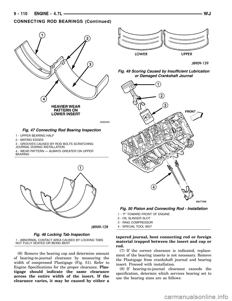
(6) Remove the bearing cap and determine amount
of bearing-to-journal clearance by measuring the
width of compressed Plastigage (Fig. 51). Refer to
Engine Specifications for the proper clearance.Plas-
tigage should indicate the same clearance
across the entire width of the insert. If the
clearance varies, it may be caused by either atapered journal, bent connecting rod or foreign
material trapped between the insert and cap or
rod.
(7) If the correct clearance is indicated, replace-
ment of the bearing inserts is not necessary. Remove
the Plastigage from crankshaft journal and bearing
insert. Proceed with installation.
(8) If bearing-to-journal clearance exceeds the
specification, determin which services bearing set to
use the bearing sizes are as follows:
Fig. 47 Connecting Rod Bearing Inspection
1 - UPPER BEARING HALF
2 - MATING EDGES
3 - GROOVES CAUSED BY ROD BOLTS SCRATCHING
JOURNAL DURING INSTALLATION
4 - WEAR PATTERN Ð ALWAYS GREATER ON UPPER
BEARING
Fig. 48 Locking Tab Inspection
1 - ABNORMAL CONTACT AREA CAUSED BY LOCKING TABS
NOT FULLY SEATED OR BEING BENT
Fig. 49 Scoring Caused by Insufficient Lubrication
or Damaged Crankshaft Journal
Fig. 50 Piston and Connecting Rod - Installation
1 - ªFº TOWARD FRONT OF ENGINE
2 - OIL SLINGER SLOT
3 - RING COMPRESSOR
4 - SPECIAL TOOL 8507
9 - 110 ENGINE - 4.7LWJ
CONNECTING ROD BEARINGS (Continued)
Page 1360 of 2199
CRANKSHAFT OIL SEAL -
REAR
REMOVAL
NOTE: This procedure can be performed in vehicle.
(1) If being preformed in vehicle, remove the
transmission.
(2) Remove the flexplate (Refer to 9 - ENGINE/
ENGINE BLOCK/FLEX PLATE - REMOVAL).
NOTE: The crankshaft oil seal CAN NOT be reused
after removal.
NOTE: The crankshaft rear oil seal remover Special
Tool 8506 must be installed deeply into the seal.
Continue to tighten the removal tool into the seal
until the tool can not be turned farther. Failure to
install tool correctly the first time will cause tool to
pull free of seal without removing seal from engine.
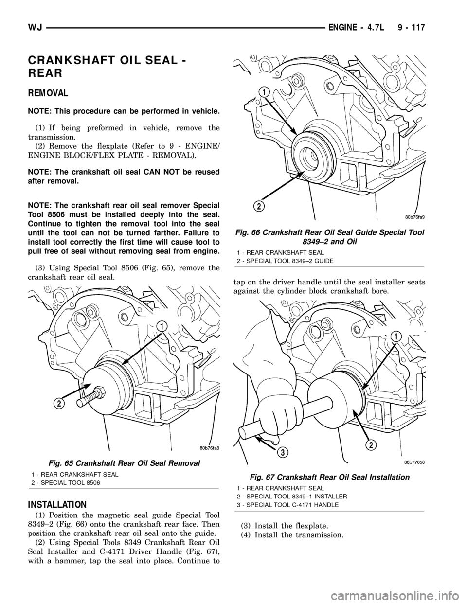
(3) Using Special Tool 8506 (Fig. 65), remove the
crankshaft rear oil seal.
INSTALLATION
(1) Position the magnetic seal guide Special Tool
8349±2 (Fig. 66) onto the crankshaft rear face. Then
position the crankshaft rear oil seal onto the guide.
(2) Using Special Tools 8349 Crankshaft Rear Oil
Seal Installer and C-4171 Driver Handle (Fig. 67),
with a hammer, tap the seal into place. Continue totap on the driver handle until the seal installer seats
against the cylinder block crankshaft bore.
(3) Install the flexplate.
(4) Install the transmission.
Fig. 65 Crankshaft Rear Oil Seal Removal
1 - REAR CRANKSHAFT SEAL
2 - SPECIAL TOOL 8506
Fig. 66 Crankshaft Rear Oil Seal Guide Special Tool
8349±2 and Oil
1 - REAR CRANKSHAFT SEAL
2 - SPECIAL TOOL 8349±2 GUIDE
Fig. 67 Crankshaft Rear Oil Seal Installation
1 - REAR CRANKSHAFT SEAL
2 - SPECIAL TOOL 8349±1 INSTALLER
3 - SPECIAL TOOL C-4171 HANDLE
WJENGINE - 4.7L 9 - 117
Page 1374 of 2199
CRANKCASE OIL LEVEL INSPECTION
CAUTION: Do not overfill crankcase with engine oil,
pressure loss or oil foaming can result.
Inspect engine oil level approximately every 800
kilometers (500 miles). Unless the engine has exhib-
ited loss of oil pressure, run the engine for about five
minutes before checking oil level. Checking engine oil
level on a cold engine is not accurate.
To ensure proper lubrication of an engine, the
engine oil must be maintained at an acceptable level.
The acceptable levels are indicated between the ADD
and SAFE marks on the engine oil dipstick.
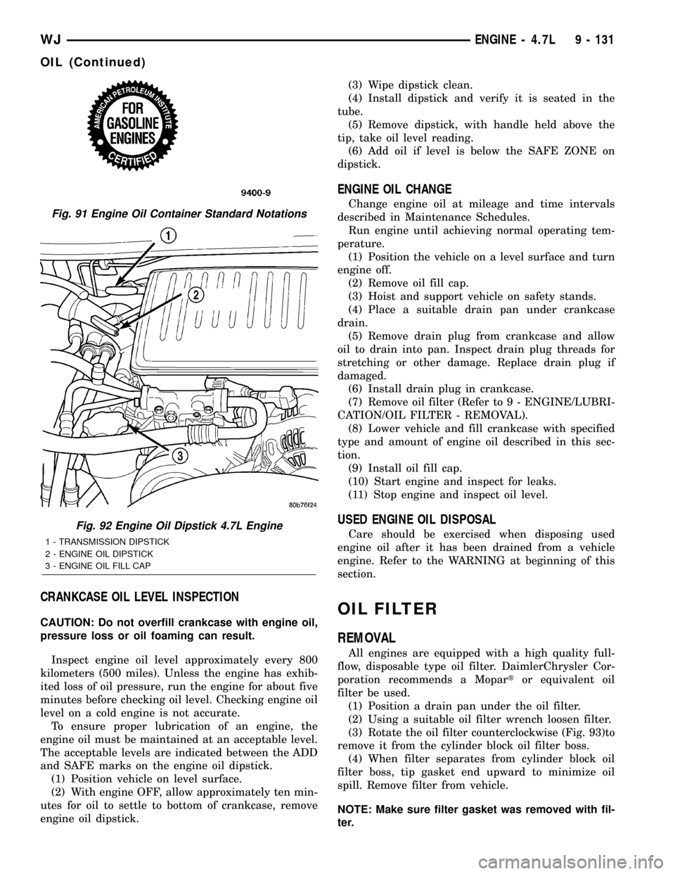
(1) Position vehicle on level surface.
(2) With engine OFF, allow approximately ten min-
utes for oil to settle to bottom of crankcase, remove
engine oil dipstick.(3) Wipe dipstick clean.
(4) Install dipstick and verify it is seated in the
tube.
(5) Remove dipstick, with handle held above the
tip, take oil level reading.
(6) Add oil if level is below the SAFE ZONE on
dipstick.
ENGINE OIL CHANGE
Change engine oil at mileage and time intervals
described in Maintenance Schedules.
Run engine until achieving normal operating tem-
perature.
(1) Position the vehicle on a level surface and turn
engine off.
(2) Remove oil fill cap.
(3) Hoist and support vehicle on safety stands.
(4) Place a suitable drain pan under crankcase
drain.
(5) Remove drain plug from crankcase and allow
oil to drain into pan. Inspect drain plug threads for
stretching or other damage. Replace drain plug if
damaged.
(6) Install drain plug in crankcase.
(7) Remove oil filter (Refer to 9 - ENGINE/LUBRI-
CATION/OIL FILTER - REMOVAL).
(8) Lower vehicle and fill crankcase with specified
type and amount of engine oil described in this sec-
tion.
(9) Install oil fill cap.
(10) Start engine and inspect for leaks.
(11) Stop engine and inspect oil level.
USED ENGINE OIL DISPOSAL
Care should be exercised when disposing used
engine oil after it has been drained from a vehicle
engine. Refer to the WARNING at beginning of this
section.
OIL FILTER
REMOVAL
All engines are equipped with a high quality full-
flow, disposable type oil filter. DaimlerChrysler Cor-
poration recommends a Mopartor equivalent oil
filter be used.
(1) Position a drain pan under the oil filter.
(2) Using a suitable oil filter wrench loosen filter.
(3) Rotate the oil filter counterclockwise (Fig. 93)to
remove it from the cylinder block oil filter boss.
(4) When filter separates from cylinder block oil
filter boss, tip gasket end upward to minimize oil
spill. Remove filter from vehicle.
NOTE: Make sure filter gasket was removed with fil-
ter.
Fig. 91 Engine Oil Container Standard Notations
Fig. 92 Engine Oil Dipstick 4.7L Engine
1 - TRANSMISSION DIPSTICK
2 - ENGINE OIL DIPSTICK
3 - ENGINE OIL FILL CAP
WJENGINE - 4.7L 9 - 131
OIL (Continued)
Page 1437 of 2199

(9) Disconnect speed control cable at throttle body
(if equipped). Refer to Speed Control Cable.
(10) Disconnect automatic transmission cable at
throttle body (if equipped).
(11) Remove cable routing bracket at intake mani-
fold.
(12) Clean dirt/debris from each fuel injector at
intake manifold.
(13) Remove fuel rail mounting nuts/bolts (Fig.
24).
(14) Remove fuel rail by gently rocking until all
fuel injectors have cleared machined holes at intake
manifold.
(15) If fuel injectors are to be removed, refer to
Fuel Injector Removal/Installation.
INSTALLATION
INSTALLATION - 4.7L
(1) If fuel injectors are to be installed, refer to Fuel
Injector Removal/Installation.
(2) Apply a small amount of engine oil to each fuel
injector o-ring. This will help in fuel rail installation.
(3) Position fuel rail/fuel injector assembly to
machined injector openings in cylinder head.
(4) Guide each injector into cylinder head. Be care-
ful not to tear injector o-rings.(5) Pushrightside of fuel rail down until fuel
injectors have bottomed on cylinder head shoulder.
Pushleftfuel rail down until injectors have bot-
tomed on cylinder head shoulder.
(6) Install 4 fuel rail mounting bolts and tighten to
27 N´m (20 ft. lbs.).
(7) Install ignition coils. Refer to Ignition Coil
Removal/Installation.
(8) Connect electrical connectors to throttle body.
(9) Connect electrical connectors to MAP and IAT
sensors.
(10) Connect electrical connectors at all fuel injec-
tors. To install connector, refer to (Fig. 23). Push con-
nector onto injector (1) and then push and lock red
colored slider (2). Verify connector is locked to injec-
tor by lightly tugging on connector.
(11) Connect vacuum lines to throttle body.
(12) Connect fuel line latch clip and fuel line to
fuel rail. Refer to Quick-Connect Fittings.
(13) Connect wiring to rear of generator.
(14) Install air box to throttle body.
(15) Install air duct to air box.
(16) Connect battery cable to battery.
(17) Start engine and check for leaks.
INSTALLATION - 4.0L
(1) If fuel injectors are to be installed, refer to Fuel
Injector Removal/Installation.
(2) Clean each injector bore at intake manifold.
(3) Apply a small amount of clean engine oil to
each injector o-ring. This will aid in installation.
(4) Position tips of all fuel injectors into the corre-
sponding injector bore in intake manifold. Seat injec-
tors into manifold.
(5) Install and tighten fuel rail mounting bolts to
11 3 N´m (100 25 in. lbs.) torque.
(6) Connect electrical connectors at all fuel injec-
tors. To install connector, refer to (Fig. 25). Push con-
nector onto injector (1) and then push and lock red
colored slider (2). Verify connector is locked to injec-
tor by lightly tugging on connector.
(7) Connect fuel line and fuel line latch clip to fuel
rail. Refer Quick-Connect Fittings.
(8) Install protective cap to pressure test port fit-
ting (if equipped).
(9) Install cable routing bracket to intake mani-
fold.
(10) Connect throttle cable at throttle body.
(11) Connect speed control cable at throttle body (if
equipped).
(12) Connect automatic transmission cable at
throttle body (if equipped).
(13) Install oxygen sensor wiring clip nuts to fuel
rail mounting studs (certain emissions packages
only).
Fig. 25 Remove/Install Injector ConnectorÐ4.0L
Engine
14 - 18 FUEL DELIVERYWJ
FUEL RAIL (Continued)
Page 1474 of 2199
REMOVAL - 4.7L
CAUTION: Be careful not to damage or kink the
cable core wire (within the cable sheathing) while
servicing accelerator pedal or throttle cable.
(1) From inside vehicle, hold up accelerator pedal.
Remove plastic cable retainer (clip) and throttle cable
core wire from upper end of pedal arm (Fig. 16).
Plastic cable retainer (clip) snaps into pedal arm.
(2) Remove cable core wire at pedal arm.
(3) From inside vehicle, remove clip holding cable
to dashpanel (Fig. 16).
(4) Remove air box at throttle body.
(5) Unsnap cable from plenum routing clip.
(6) Remove cable housing from dash panel and
pull into engine compartment.
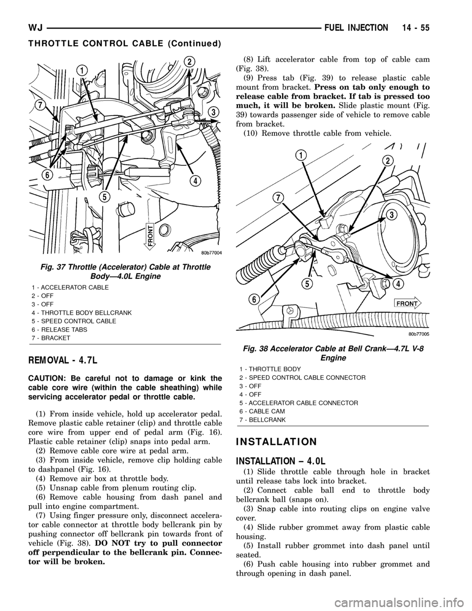
(7) Using finger pressure only, disconnect accelera-
tor cable connector at throttle body bellcrank pin by
pushing connector off bellcrank pin towards front of
vehicle (Fig. 38).DO NOT try to pull connector
off perpendicular to the bellcrank pin. Connec-
tor will be broken.(8) Lift accelerator cable from top of cable cam
(Fig. 38).
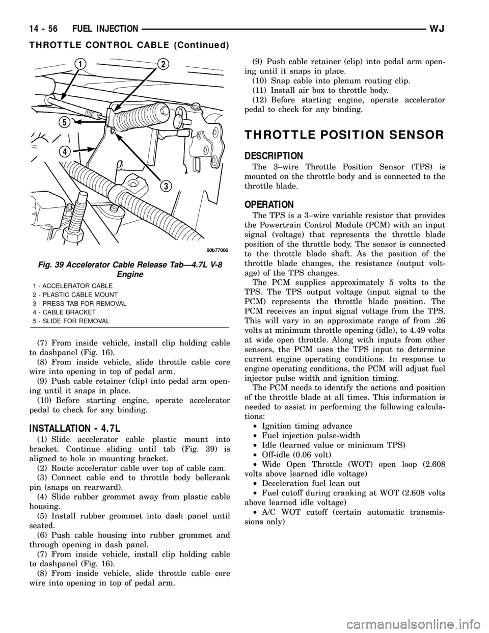
(9) Press tab (Fig. 39) to release plastic cable
mount from bracket.Press on tab only enough to
release cable from bracket. If tab is pressed too
much, it will be broken.Slide plastic mount (Fig.
39) towards passenger side of vehicle to remove cable
from bracket.
(10) Remove throttle cable from vehicle.
INSTALLATION
INSTALLATION ± 4.0L
(1) Slide throttle cable through hole in bracket
until release tabs lock into bracket.
(2) Connect cable ball end to throttle body
bellcrank ball (snaps on).
(3) Snap cable into routing clips on engine valve
cover.
(4) Slide rubber grommet away from plastic cable
housing.
(5) Install rubber grommet into dash panel until
seated.
(6) Push cable housing into rubber grommet and
through opening in dash panel.
Fig. 37 Throttle (Accelerator) Cable at Throttle
BodyÐ4.0L Engine
1 - ACCELERATOR CABLE
2 - OFF
3 - OFF
4 - THROTTLE BODY BELLCRANK
5 - SPEED CONTROL CABLE
6 - RELEASE TABS
7 - BRACKET
Fig. 38 Accelerator Cable at Bell CrankÐ4.7L V-8
Engine
1 - THROTTLE BODY
2 - SPEED CONTROL CABLE CONNECTOR
3 - OFF
4 - OFF
5 - ACCELERATOR CABLE CONNECTOR
6 - CABLE CAM
7 - BELLCRANK
WJFUEL INJECTION 14 - 55
THROTTLE CONTROL CABLE (Continued)
Page 1475 of 2199
(7) From inside vehicle, install clip holding cable
to dashpanel (Fig. 16).
(8) From inside vehicle, slide throttle cable core
wire into opening in top of pedal arm.
(9) Push cable retainer (clip) into pedal arm open-
ing until it snaps in place.
(10) Before starting engine, operate accelerator
pedal to check for any binding.
INSTALLATION - 4.7L
(1) Slide accelerator cable plastic mount into
bracket. Continue sliding until tab (Fig. 39) is
aligned to hole in mounting bracket.
(2) Route accelerator cable over top of cable cam.
(3) Connect cable end to throttle body bellcrank
pin (snaps on rearward).
(4) Slide rubber grommet away from plastic cable
housing.
(5) Install rubber grommet into dash panel until
seated.
(6) Push cable housing into rubber grommet and
through opening in dash panel.
(7) From inside vehicle, install clip holding cable
to dashpanel (Fig. 16).
(8) From inside vehicle, slide throttle cable core
wire into opening in top of pedal arm.(9) Push cable retainer (clip) into pedal arm open-
ing until it snaps in place.
(10) Snap cable into plenum routing clip.
(11) Install air box to throttle body.
(12) Before starting engine, operate accelerator
pedal to check for any binding.
THROTTLE POSITION SENSOR
DESCRIPTION
The 3±wire Throttle Position Sensor (TPS) is
mounted on the throttle body and is connected to the
throttle blade.
OPERATION
The TPS is a 3±wire variable resistor that provides
the Powertrain Control Module (PCM) with an input
signal (voltage) that represents the throttle blade
position of the throttle body. The sensor is connected
to the throttle blade shaft. As the position of the
throttle blade changes, the resistance (output volt-
age) of the TPS changes.
The PCM supplies approximately 5 volts to the
TPS. The TPS output voltage (input signal to the
PCM) represents the throttle blade position. The
PCM receives an input signal voltage from the TPS.
This will vary in an approximate range of from .26
volts at minimum throttle opening (idle), to 4.49 volts
at wide open throttle. Along with inputs from other
sensors, the PCM uses the TPS input to determine
current engine operating conditions. In response to
engine operating conditions, the PCM will adjust fuel
injector pulse width and ignition timing.
The PCM needs to identify the actions and position
of the throttle blade at all times. This information is
needed to assist in performing the following calcula-
tions:
²Ignition timing advance
²Fuel injection pulse-width
²Idle (learned value or minimum TPS)
²Off-idle (0.06 volt)
²Wide Open Throttle (WOT) open loop (2.608
volts above learned idle voltage)
²Deceleration fuel lean out
²Fuel cutoff during cranking at WOT (2.608 volts
above learned idle voltage)
²A/C WOT cutoff (certain automatic transmis-
sions only)
Fig. 39 Accelerator Cable Release TabÐ4.7L V-8
Engine
1 - ACCELERATOR CABLE
2 - PLASTIC CABLE MOUNT
3 - PRESS TAB FOR REMOVAL
4 - CABLE BRACKET
5 - SLIDE FOR REMOVAL
14 - 56 FUEL INJECTIONWJ
THROTTLE CONTROL CABLE (Continued)
Page 1485 of 2199
REMOVAL
WARNING: BEFORE SERVICING THE STEERING
COLUMN THE AIRBAG SYSTEM MUST BE DIS-
ARMED. FAILURE TO DO SO MAY RESULT IN ACCI-
DENTAL DEPLOYMENT OF THE AIRBAG AND
POSSIBLE PERSONAL INJURY.(Refer to 8 - ELEC-
TRICAL/RESTRAINTS/DRIVER AIRBAG - REMOVAL).
(1) Position front wheels straight ahead.
(2) Disconnect and isolate the negative (ground)
cable from the battery.
(3) Remove the airbag,(Refer to 8 - ELECTRICAL/
RESTRAINTS/DRIVER AIRBAG - REMOVAL).
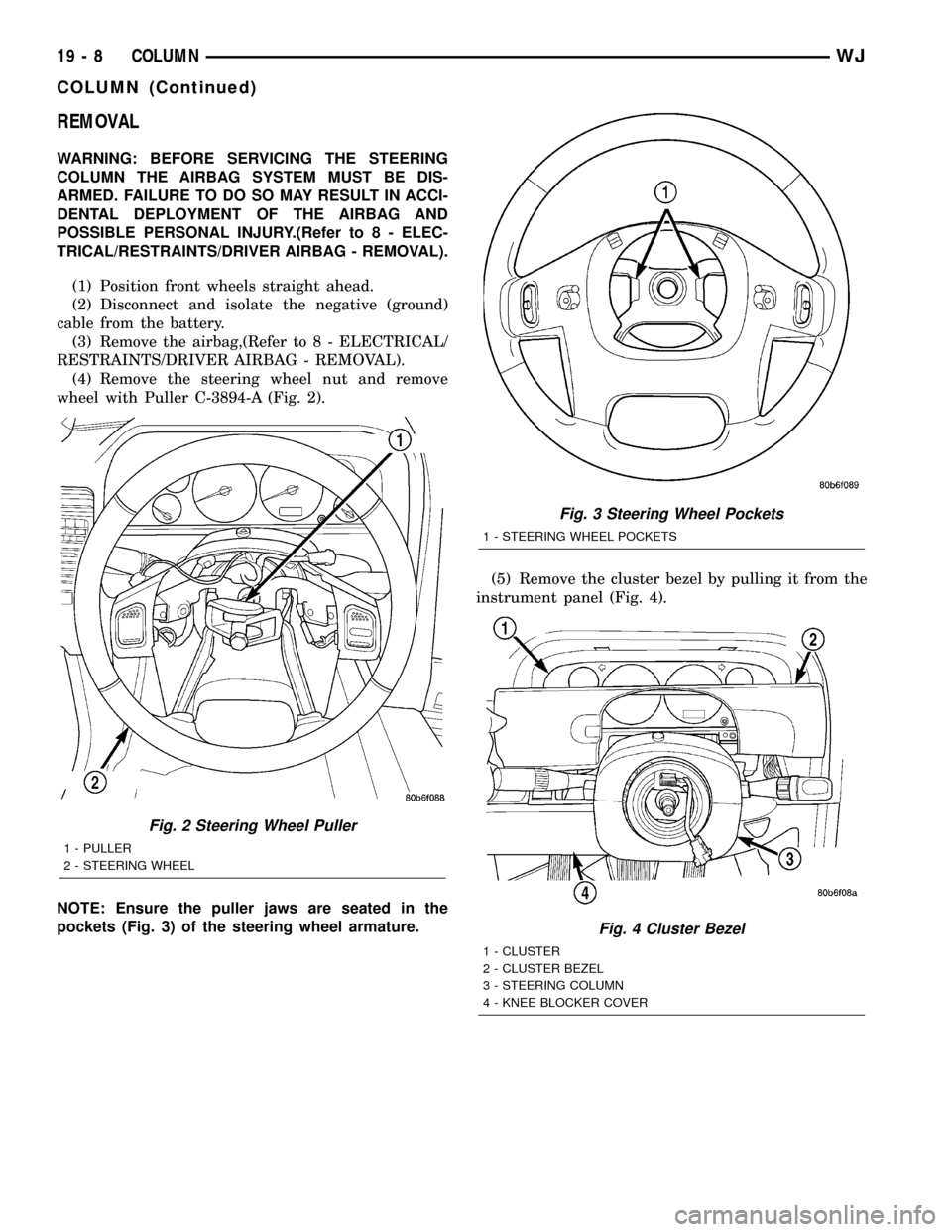
(4) Remove the steering wheel nut and remove
wheel with Puller C-3894-A (Fig. 2).
NOTE: Ensure the puller jaws are seated in the
pockets (Fig. 3) of the steering wheel armature.(5) Remove the cluster bezel by pulling it from the
instrument panel (Fig. 4).
Fig. 2 Steering Wheel Puller
1 - PULLER
2 - STEERING WHEEL
Fig. 3 Steering Wheel Pockets
1 - STEERING WHEEL POCKETS
Fig. 4 Cluster Bezel
1 - CLUSTER
2 - CLUSTER BEZEL
3 - STEERING COLUMN
4 - KNEE BLOCKER COVER
19 - 8 COLUMNWJ
COLUMN (Continued)
Page 1490 of 2199
necessary, the steering column assembly must be
replaced,(Refer to 19 - STEERING/COLUMN -
REMOVAL).
REMOVAL
IGNITION SWITCH REMOVAL
The ignition key must be in the key cylinder for
cylinder removal. The key cylinder must be removed
first before removing ignition switch.
(1) Remove key cylinder. Refer to previous steps.
(2) Remove lower steering column cover screws
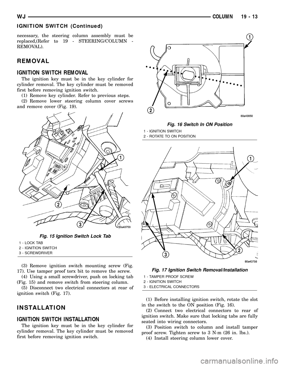
and remove cover (Fig. 19).
(3) Remove ignition switch mounting screw (Fig.
17). Use tamper proof torx bit to remove the screw.
(4) Using a small screwdriver, push on locking tab
(Fig. 15) and remove switch from steering column.
(5) Disconnect two electrical connectors at rear of
ignition switch (Fig. 17).
INSTALLATION
IGNITION SWITCH INSTALLATION
The ignition key must be in the key cylinder for
cylinder removal. The key cylinder must be removed
first before removing ignition switch.(1) Before installing ignition switch, rotate the slot
in the switch to the ON position (Fig. 16).
(2) Connect two electrical connectors to rear of
ignition switch. Make sure that locking tabs are fully
seated into wiring connectors.
(3) Position switch to column and install tamper
proof screw. Tighten screw to 3 N´m (26 in. lbs.).
(4) Install steering column lower cover.
Fig. 15 Ignition Switch Lock Tab
1 - LOCK TAB
2 - IGNITION SWITCH
3 - SCREWDRIVER
Fig. 16 Switch In ON Position
1 - IGNITION SWITCH
2 - ROTATE TO ON POSITION
Fig. 17 Ignition Switch Removal/Installation
1 - TAMPER PROOF SCREW
2 - IGNITION SWITCH
3 - ELECTRICAL CONNECTORS
WJCOLUMN 19 - 13
IGNITION SWITCH (Continued)
Page 1498 of 2199
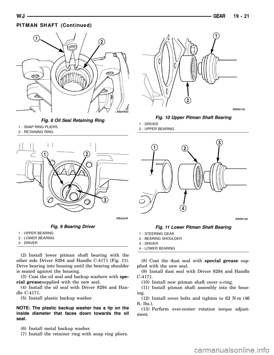
(2) Install lower pitman shaft bearing with the
other side Driver 8294 and Handle C-4171 (Fig. 11).
Drive bearing into housing until the bearing shoulder
is seated against the housing.
(3) Coat the oil seal and backup washers withspe-
cial greasesupplied with the new seal.
(4) Install the oil seal with Driver 8294 and Han-
dle C-4171.
(5) Install plastic backup washer.
NOTE: The plastic backup washer has a lip on the
inside diameter that faces down towards the oil
seal.
(6) Install metal backup washer.
(7) Install the retainer ring with snap ring pliers.(8) Coat the dust seal withspecial greasesup-
plied with the new seal.
(9) Install dust seal with Driver 8294 and Handle
C-4171.
(10) Install new pitman shaft cover o-ring.
(11) Install pitman shaft assembly into the hous-
ing.
(12) Install cover bolts and tighten to 62 N´m (46
ft. lbs.).
(13) Perform over-center rotation torque adjust-
ment.
Fig. 8 Oil Seal Retaining Ring
1 - SNAP RING PLIERS
2 - RETAINING RING
Fig. 9 Bearing Driver
1 - UPPER BEARING
2 - LOWER BEARING
3 - DRIVER
Fig. 10 Upper Pitman Shaft Bearing
1 - DRIVER
2 - UPPER BEARING
Fig. 11 Lower Pitman Shaft Bearing
1 - STEERING GEAR
2 - BEARING SHOULDER
3 - DRIVER
4 - LOWER BEARING
WJGEAR 19 - 21
PITMAN SHAFT (Continued)
Page 1499 of 2199
PITMAN SHAFT BEARING
REMOVAL
(1) Clean exposed end of pitman shaft and housing
with a wire brush.
(2) Rotate the stub shaft with a wrench (Fig.
5)from stop to stop and count the number of turns.
(3) Center the stub shaft by rotating it from the
stop 1/2 of the total amount of turns.
NOTE: The pitman shaft will not clear the housing if
it is not centered.
(4) Remove pitman shaft cover bolts and remove
the shaft assembly (Fig. 6).
(5) Remove pitman shaft cover o-ring.
(6) Remove pitman shaft dust seal from the hous-
ing with a Puller 7794-A and Slide Hammer C-637
(Fig. 7).
(7) Remove the pitman shaft oil seal retaining ring
with snap ring pliers (Fig. 8).
(8) Remove oil seal metal backup washer then
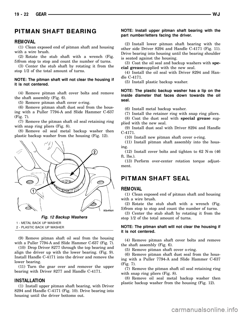
plastic backup washer from the housing (Fig. 12).
(9)
Remove pitman shaft oil seal from the housing
with a Puller 7794-A and Slide Hammer C-637 (Fig. 7).
(10) Drop Driver 8277 through the top bearing and
align the driver up with the lower bearing. (Fig. 9).
Install Handle C-4171 into the driver and remove the
lower bearing.
(11) Turn the gear over and remover the upper
bearing with Driver 8277 and Handle C-4171.
INSTALLATION
(1) Install upper pitman shaft bearing, with Driver
8294 and Handle C-4171 (Fig. 10). Drive bearing into
housing until the driver bottoms out.NOTE: Install upper pitman shaft bearing with the
part number/letters facing the driver.
(2) Install lower pitman shaft bearing with the
other side Driver 8294 and Handle C-4171 (Fig. 11).
Drive bearing into housing until the bearing shoulder
is seated against the housing.
(3) Coat the oil seal and backup washers withspe-
cial greasesupplied with the new seal.
(4) Install the oil seal with Driver 8294 and Han-
dle C-4171.
(5) Install plastic backup washer.
NOTE: The plastic backup washer has a lip on the
inside diameter that faces down towards the oil
seal.
(6) Install metal backup washer.
(7) Install the retainer ring with snap ring pliers.
(8) Coat the dust seal withspecial greasesup-
plied with the new seal.
(9) Install dust seal with Driver 8294 and Handle
C-4171.
(10) Install new pitman shaft cover o-ring.
(11) Install pitman shaft assembly into the hous-
ing.
(12) Install cover bolts and tighten to 62 N´m (46
ft. lbs.).
(13) Perform over-center rotation torque adjust-
ment.
PITMAN SHAFT SEAL
REMOVAL
(1) Clean exposed end of pitman shaft and housing
with a wire brush.
(2) Rotate the stub shaft with a wrench (Fig.
5)from stop to stop and count the number of turns.
(3) Center the stub shaft by rotating it from the
stop 1/2 of the total amount of turns.
NOTE: The pitman shaft will not clear the housing if
it is not centered.
(4) Remove pitman shaft cover bolts and remove
the shaft assembly (Fig. 6).
(5) Remove pitman shaft cover o-ring.
(6) Remove pitman shaft dust seal from the hous-
ing with a Puller 7794-A and Slide Hammer C-637
(Fig. 7).
(7) Remove the pitman shaft oil seal retaining ring
with snap ring pliers (Fig. 8).
(8) Remove oil seal metal backup washer then
plastic backup washer from the housing (Fig. 12).
Fig. 12 Backup Washers
1 - METAL BACK UP WASHER
2 - PLASTIC BACK UP WASHER
19 - 22 GEARWJ