o2 location JEEP GRAND CHEROKEE 2002 WJ / 2.G Workshop Manual
[x] Cancel search | Manufacturer: JEEP, Model Year: 2002, Model line: GRAND CHEROKEE, Model: JEEP GRAND CHEROKEE 2002 WJ / 2.GPages: 2199, PDF Size: 76.01 MB
Page 1549 of 2199

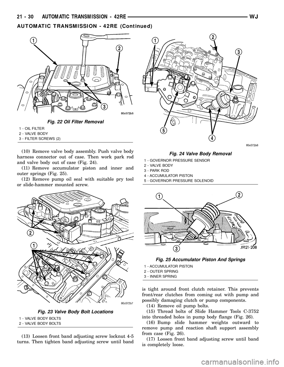
(10) Remove valve body assembly. Push valve body
harness connector out of case. Then work park rod
and valve body out of case (Fig. 24).
(11) Remove accumulator piston and inner and
outer springs (Fig. 25).
(12) Remove pump oil seal with suitable pry tool
or slide-hammer mounted screw.
(13) Loosen front band adjusting screw locknut 4-5
turns. Then tighten band adjusting screw until bandis tight around front clutch retainer. This prevents
front/rear clutches from coming out with pump and
possibly damaging clutch or pump components.
(14) Remove oil pump bolts.
(15) Thread bolts of Slide Hammer Tools C-3752
into threaded holes in pump body flange (Fig. 26).
(16) Bump slide hammer weights outward to
remove pump and reaction shaft support assembly
from case (Fig. 26).
(17) Loosen front band adjusting screw until band
is completely loose.
Fig. 22 Oil Filter Removal
1 - OIL FILTER
2 - VALVE BODY
3 - FILTER SCREWS (2)
Fig. 23 Valve Body Bolt Locations
1 - VALVE BODY BOLTS
2 - VALVE BODY BOLTS
Fig. 24 Valve Body Removal
1 - GOVERNOR PRESSURE SENSOR
2 - VALVE BODY
3 - PARK ROD
4 - ACCUMULATOR PISTON
5 - GOVERNOR PRESSURE SOLENOID
Fig. 25 Accumulator Piston And Springs
1 - ACCUMULATOR PISTON
2 - OUTER SPRING
3 - INNER SPRING
21 - 30 AUTOMATIC TRANSMISSION - 42REWJ
AUTOMATIC TRANSMISSION - 42RE (Continued)
Page 1556 of 2199

(10) Install thrust plate on intermediate shaft hub
(Fig. 47). Use petroleum jelly to hold thrust plate in
place.
(11) Check seal ring on rear clutch retainer hub
and seal rings on input shaft (Fig. 48). Also verify
that shaft seal rings are installed in sequence shown.
(12) Install rear clutch thrust washer (Fig. 49).
Use additional petroleum jelly to hold washer in
place if necessary.
(13) Align clutch discs in front clutch and install
front clutch on rear clutch (Fig. 50). Rotate front
clutch retainer back and forth until completely
seated on rear clutch retainer.
(14) Coat intermediate shaft thrust washer with
petroleum jelly. Then install washer in rear clutch
hub (Fig. 51). Use enough petroleum jelly to hold
washer in place. Be sure grooved side of washer faces
rearward (toward output shaft) as shown. Also note
that washer only fits one way in clutch hub. Note
thickness of this washer. It is a select fit part and is
used to control transmission end play.
Fig. 46 Installing Planetary Geartrain
1 - PLANETARY GEARTRAIN AND INTERMEDIATE SHAFT
ASSEMBLY
Fig. 47 Installing Intermediate Shaft Thrust Plate
1 - INTERMEDIATE SHAFT HUB
2 - INTERMEDIATE SHAFT THRUST PLATE
Fig. 48 Input Shaft Seal Ring Location
1 - INPUT SHAFT
2 - TEFLON SEAL RING
3 - PLASTIC SEAL RING
4 - REAR CLUTCH RETAINER
Fig. 49 Installing Rear Clutch Thrust Washer
1 - REAR CLUTCH RETAINER
2 - REAR CLUTCH THRUST WASHER (FIBER)
WJAUTOMATIC TRANSMISSION - 42RE 21 - 37
AUTOMATIC TRANSMISSION - 42RE (Continued)
Page 1581 of 2199

ADJUSTMENTS
ADJUSTMENT - BANDS
FRONT BAND
The front (kickdown) band adjusting screw is
located on the left side of the transmission case
above the manual valve and throttle valve levers.
(1) Raise vehicle.
(2) Loosen band adjusting screw locknut (Fig. 69).
Then back locknut off 3-5 turns. Be sure adjusting
screw turns freely in case. Apply lubricant to screw
threads if necessary.
(3) Tighten band adjusting screw to 8 N´m (72 in.
lbs.) torque with Inch Pound Torque Wrench
C-3380-A, a 3-in. extension and appropriate TorxŸ
socket.
CAUTION: If Adapter C-3705 is needed to reach the
adjusting screw, tighten the screw to only 5 N´m
(47-50 in. lbs.) torque.
(4) Back off front band adjusting screw 3 turns.
(5) Hold adjuster screw in position and tighten
locknut to 41 N´m (30 ft. lbs.) torque.
(6) Lower vehicle.
REAR BAND
The transmission oil pan must be removed for
access to the rear band adjusting screw.
(1) Raise vehicle.
(2) Remove transmission oil pan and drain fluid.(3) Loosen band adjusting screw locknut 5-6 turns
(Fig. 70). Be sure adjusting screw turns freely in
lever.
(4) Tighten adjusting screw to 8 N´m (72 in. lbs.)
torque.
(5) Back off adjusting screw 4 turns.
(6) Hold adjusting screw in place and tighten lock-
nut to 34 N´m (25 ft. lbs.) torque.
(7) Position new gasket on oil pan and install pan
on transmission. Tighten pan bolts to 17 N´m (13 ft.
lbs.) torque.
(8) Lower vehicle and refill transmission with
MopartATF +4, type 9602, fluid.
Fig. 68 Rear Band
1 - ADJUSTING SCREW
2 - LOCKNUT
3 - LEVER
4 - REAR BAND
5 - REACTION PIN
6 - O-RINGS
7 - PIVOT PINFig. 69 Front Band Adjustment Screw Location
1 - LOCK-NUT
2 - FRONT BAND ADJUSTER
Fig. 70 Rear Band Adjusting Screw Location
1 - ADJUSTING SCREW
2 - REAR BAND LEVER
3 - LOCKNUT
21 - 62 AUTOMATIC TRANSMISSION - 42REWJ
BANDS (Continued)
Page 1595 of 2199

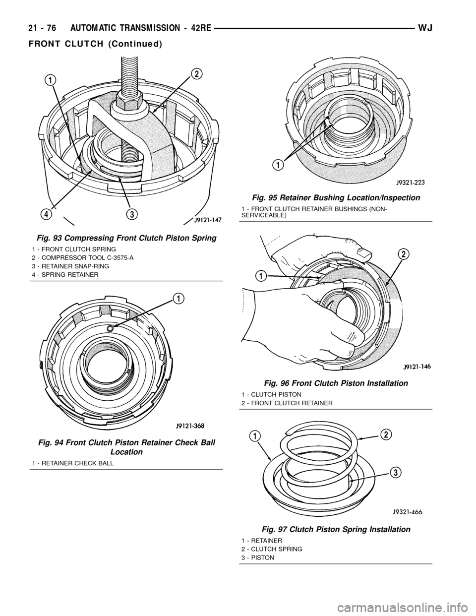
Fig. 93 Compressing Front Clutch Piston Spring
1 - FRONT CLUTCH SPRING
2 - COMPRESSOR TOOL C-3575-A
3 - RETAINER SNAP-RING
4 - SPRING RETAINER
Fig. 94 Front Clutch Piston Retainer Check Ball
Location
1 - RETAINER CHECK BALL
Fig. 95 Retainer Bushing Location/Inspection
1 - FRONT CLUTCH RETAINER BUSHINGS (NON-
SERVICEABLE)
Fig. 96 Front Clutch Piston Installation
1 - CLUTCH PISTON
2 - FRONT CLUTCH RETAINER
Fig. 97 Clutch Piston Spring Installation
1 - RETAINER
2 - CLUTCH SPRING
3 - PISTON
21 - 76 AUTOMATIC TRANSMISSION - 42REWJ
FRONT CLUTCH (Continued)
Page 1607 of 2199

DISASSEMBLY
(1) Remove transmission speed sensor and O-ring
seal from overdrive case (Fig. 127).
(2) Remove overdrive piston thrust bearing (Fig.
128).
OVERDRIVE PISTON
(1) Remove overdrive piston thrust plate (Fig.
129). Retain thrust plate. It is a select fit part and
may possibly be reused.
(2) Remove intermediate shaft spacer (Fig. 130).
Retain spacer. It is a select fit part and may possibly
be reused.
(3) Remove overdrive piston from retainer (Fig.
131).
Fig. 127 Transmission Speed Sensor Removal
1 - SOCKET AND WRENCH
2 - SPEED SENSOR
3 - O-RING
Fig. 128 Overdrive Piston Thrust Bearing Removal
1 - THRUST BEARING
2 - OVERDRIVE PISTON
3 - THRUST PLATE
Fig. 129 Overdrive Piston Thrust Plate Removal
1 - OVERDRIVE PISTON
2 - OVERDRIVE PISTON SPACER (SELECT FIT)
Fig. 130 Intermediate Shaft Spacer Location
1 - INTERMEDIATE SHAFT
2 - INTERMEDIATE SHAFT SPACER (SELECT FIT)
21 - 88 AUTOMATIC TRANSMISSION - 42REWJ
OVERDRIVE UNIT (Continued)
Page 1624 of 2199

CAUTION: Be sure the shoulder on the inside diam-
eter of the bearing is facing forward.
(8) Verify that splines in overdrive planetary gear
and overrunning clutch hub are aligned with Align-
ment Tool 6227-2. Overdrive unit cannot be installed
if splines are not aligned. If splines have rotated out
of alignment, unit will have to be disassembled to
realign splines.
(9) Carefully slide Alignment Tool 6227-2 out of
overdrive planetary gear and overrunning clutch
splines.
(10) Raise overdrive unit and carefully slide it
straight onto intermediate shaft. Insert park rod into
park lock reaction plug at same time. Avoid tilting
overdrive during installation as this could cause
planetary gear and overrunning clutch splines to
rotate out of alignment. If this occurs, it will be nec-essary to remove and disassemble overdrive unit to
realign splines.
(11) Work overdrive unit forward on intermediate
shaft until seated against transmission case.
(12) Install bolts attaching overdrive unit to trans-
mission unit. Tighten bolts in diagonal pattern to 34
N´m (25 ft-lbs).
(13) Connect the transmission speed sensor and
overdrive wiring connectors.
(14) Install the transfer case, if equipped.
(15) Align and install rear propeller shaft, if nec-
essary. (Refer to 3 - DIFFERENTIAL & DRIVELINE/
PROPELLER SHAFT/PROPELLER SHAFT -
INSTALLATION)
OVERRUNNING CLUTCH
CAM/OVERDRIVE PISTON
RETAINER
DESCRIPTION
The overrunning clutch (Fig. 189) consists of an
inner race, an outer race (or cam), rollers and
springs, and the spring retainer. The number of roll-
ers and springs depends on what transmission and
which overrunning clutch is being dealt with.
OPERATION
As the inner race is rotated in a clockwise direction
(as viewed from the front of the transmission), the
race causes the rollers to roll toward the springs,
causing them to compress against their retainer. The
compression of the springs increases the clearance
Fig. 187 Trimming Overdrive Case Gasket
1 - GASKET
2 - SHARP KNIFE
Fig. 188 Intermediate Shaft Selective Spacer
Location
1 - SELECTIVE SPACER
2 - SPACER GROOVE
3 - INTERMEDIATE SHAFT
Fig. 189 Overrunning Clutch
1 - OUTER RACE (CAM)
2 - ROLLER
3 - SPRING
4 - SPRING RETAINER
5 - INNER RACE (HUB)
WJAUTOMATIC TRANSMISSION - 42RE 21 - 105
OVERDRIVE UNIT (Continued)
Page 1625 of 2199

between the rollers and cam. This increased clear-
ance between the rollers and cam results in a free-
wheeling condition. When the inner race attempts to
rotate counterclockwise, the action causes the rollers
to roll in the same direction as the race, aided by the
pushing of the springs. As the rollers try to move in
the same direction as the inner race, they are
wedged between the inner and outer races due to the
design of the cam. In this condition, the clutch is
locked and acts as one unit.
DISASSEMBLY
NOTE: To service the overrunning clutch cam and
the overdrive piston retainer, the transmission
geartrain and the overdrive unit must be removed
from the transmission.
(1) Remove the overdrive piston (Fig. 190).
(2) Remove the overdrive piston retainer bolts.
(3) Remove overdrive piston retainer.
(4) Remove case gasket.
(5) Mark the position of the overrunning clutch
cam in the case (Fig. 191).
(6) Remove the overrunning clutch cam bolts.
(7) Remove the overrunning clutch cam.
CLEANING
Clean the overrunning clutch assembly, clutch cam,
low-reverse drum, and overdrive piston retainer in
solvent. Dry them with compressed air after clean-
ing.
INSPECTION
Inspect condition of each clutch part after cleaning.
Replace the overrunning clutch roller and spring
assembly if any rollers or springs are worn or dam-
aged, or if the roller cage is distorted, or damaged.
Replace the cam if worn, cracked or damaged.
Replace the low-reverse drum if the clutch race,
roller surface or inside diameter is scored, worn or
damaged.Do not remove the clutch race from
the low-reverse drum under any circumstances.
Replace the drum and race as an assembly if
either component is damaged.
Examine the overdrive piston retainer carefully for
wear, cracks, scoring or other damage. Be sure the
retainer hub is a snug fit in the case and drum.
Replace the retainer if worn or damaged.
ASSEMBLY
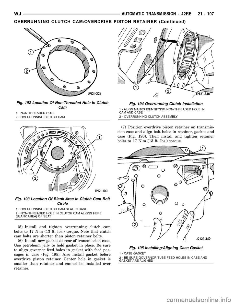
(1) Examine bolt holes in overrunning clutch cam.
Note that one hole isnot threaded(Fig. 192). This
hole must align with blank area in clutch cam bolt
circle (Fig. 193). Mark hole location on clutch cam
and blank area in case with grease pencil, paint
stripe, or scribe mark for assembly reference.
(2) Mark location of non-threaded hole in clutch
cam and blank area in bolt circle with grease pencil.
(3) Align and install overrunning clutch and cam
in case (Fig. 194). Be sure cam is correctly installed.
Bolt holes in cam are slightly countersunk on one
side. Be sure this side of cam faces rearward (toward
piston retainer).
(4) Verify that non-threaded hole in clutch cam is
properly aligned. Check alignment by threading a
bolt into each bolt hole. Adjust clutch cam position if
necessary.
Fig. 190 Overdrive Piston Removal
1 - OVERDRIVE CLUTCH PISTON
2 - INTERMEDIATE SHAFT
3 - SELECTIVE SPACER
4 - PISTON RETAINER
Fig. 191 Overrunning Clutch Cam Removal
1 - ALIGN MARKS IDENTIFYING NON-THREADED HOLE IN
CAM AND CASE
2 - OVERRUNNING CLUTCH ASSEMBLY
21 - 106 AUTOMATIC TRANSMISSION - 42REWJ
OVERRUNNING CLUTCH CAM/OVERDRIVE PISTON RETAINER (Continued)
Page 1626 of 2199

(5) Install and tighten overrunning clutch cam
bolts to 17 N´m (13 ft. lbs.) torque. Note that clutch
cam bolts are shorter than piston retainer bolts.
(6) Install new gasket at rear of transmission case.
Use petroleum jelly to hold gasket in place. Be sure
to align governor feed holes in gasket with feed pas-
sages in case (Fig. 195). Also install gasket before
overdrive piston retainer. Center hole in gasket is
smaller than retainer and cannot be installed over
retainer.(7) Position overdrive piston retainer on transmis-
sion case and align bolt holes in retainer, gasket and
case (Fig. 196). Then install and tighten retainer
bolts to 17 N´m (13 ft. lbs.) torque.
Fig. 192 Location Of Non-Threaded Hole In Clutch
Cam
1 - NON-THREADED HOLE
2 - OVERRUNNING CLUTCH CAM
Fig. 193 Location Of Blank Area In Clutch Cam Bolt
Circle
1 - OVERRUNNING CLUTCH CAM SEAT IN CASE
2 - NON-THREADED HOLE IN CLUTCH CAM ALIGNS HERE
(BLANK AREA) OF SEAT
Fig. 194 Overrunning Clutch Installation
1 - ALIGN MARKS IDENTIFYING NON-THREADED HOLE IN
CAM AND CASE
2 - OVERRUNNING CLUTCH ASSEMBLY
Fig. 195 Installing/Aligning Case Gasket
1 - CASE GASKET
2 - BE SURE GOVERNOR TUBE FEED HOLES IN CASE AND
GASKET ARE ALIGNED
WJAUTOMATIC TRANSMISSION - 42RE 21 - 107
OVERRUNNING CLUTCH CAM/OVERDRIVE PISTON RETAINER (Continued)
Page 1632 of 2199

INSPECTION
Check sun gear and driving shell condition.
Replace the gear if damaged or if the bushings are
scored or worn. The bushings are not serviceable.
Replace the driving shell if worn, cracked or dam-
aged.Replace planetary gear sets if gears, pinion pins, or
carrier are damaged in any way. Replace the annulus
gears and supports if either component is worn or
damaged.
Inspect the geartrain spacers, thrust plates, snap-
rings, and thrust washers. Replace any of these parts
that are worn, distorted or damaged. Do not attempt
to reuse these parts.
The planetary gear thrust washers are different
sizes. The large diameter washers go on the front
planetary and the smaller washers go on the rear
planetary. All the washers have four locating tabs on
them. These tabs fit in the holes or slots provided in
each planetary gear.
Inspect the output shaft carefully. Pay particular
attention to the machined bushing/bearing surfaces
on the shaft and the governor valve shaft bore at the
shaft rear.
Replace the output shaft if the machined surfaces
are scored, pitted, or damaged in any way. Also
replace the shaft if the splines are damaged, or
exhibits cracks at any location (especially at the gov-
ernor valve shaft bore).
The annulus gears can be removed from their sup-
ports if necessary. Just remove the snap-rings and
separate the two parts when replacement is neces-
sary. In addition, the annulus gear bushings can be
replaced if severely worn, or scored. However it is not
necessary to replace the bushings if they only exhibit
normal wear. Check bushing fit on the output shaft
to be sure.
ASSEMBLY
(1) Lubricate output shaft and planetary compo-
nents with transmission fluid. Use petroleum jelly to
lubricate and hold thrust washers and plates in posi-
tion.
(2) Assemble rear annulus gear and support if dis-
assembled. Be sure support snap-ring is seated and
that shoulder-side of support faces rearward (Fig.
208).
(3) Install rear thrust washer on rear planetary
gear. Use enough petroleum jelly to hold washer in
place. Also be sure all four washer tabs are properly
engaged in gear slots.
(4) Install rear annulus over and onto rear plane-
tary gear (Fig. 208).
(5) Install assembled rear planetary and annulus
gear on output shaft (Fig. 209). Verify that assembly
is fully seated on shaft.
Fig. 206 Front Planetary And Annulus Gear
Disassembly
1 - FRONT ANNULUS
2 - THRUST WASHER
3 - THRUST PLATE
4 - FRONT THRUST WASHER
5 - FRONT PLANETARY
Fig. 207 Removing Driving Shell, Rear Planetary
And Rear Annulus
1 - REAR ANNULUS
2 - REAR PLANETARY
3 - DRIVING SHELL
4 - OUTPUT SHAFT
WJAUTOMATIC TRANSMISSION - 42RE 21 - 113
PLANETARY GEARTRAIN/OUTPUT SHAFT (Continued)
Page 1650 of 2199

STATOR
The stator assembly (Fig. 248) is mounted on a sta-
tionary shaft which is an integral part of the oil
pump. The stator is located between the impeller and
turbine within the torque converter case (Fig. 249).
The stator contains an over-running clutch, which
allows the stator to rotate only in a clockwise direc-
tion. When the stator is locked against the over-run-
ning clutch, the torque multiplication feature of the
torque converter is operational.
TORQUE CONVERTER CLUTCH (TCC)
The TCC (Fig. 250) was installed to improve the
efficiency of the torque converter that is lost to the
slippage of the fluid coupling. Although the fluid cou-
pling provides smooth, shock-free power transfer, it is
natural for all fluid couplings to slip. If the impeller
and turbine were mechanically locked together, a
zero slippage condition could be obtained. A hydraulic
piston was added to the turbine, and a friction mate-
rial was added to the inside of the front cover to pro-
vide this mechanical lock-up.
Fig. 248 Stator Components
1 - CAM (OUTER RACE)
2 - ROLLER
3 - SPRING
4 - INNER RACE
Fig. 249 Stator Location
1-STATOR
2 - IMPELLER
3 - FLUID FLOW
4 - TURBINE
Fig. 250 Torque Converter Clutch (TCC)
1 - IMPELLER FRONT COVER
2 - THRUST WASHER ASSEMBLY
3 - IMPELLER
4-STATOR
5 - TURBINE
6 - PISTON
7 - FRICTION DISC
WJAUTOMATIC TRANSMISSION - 42RE 21 - 131
TORQUE CONVERTER (Continued)