Cable JEEP GRAND CHEROKEE 2002 WJ / 2.G Workshop Manual
[x] Cancel search | Manufacturer: JEEP, Model Year: 2002, Model line: GRAND CHEROKEE, Model: JEEP GRAND CHEROKEE 2002 WJ / 2.GPages: 2199, PDF Size: 76.01 MB
Page 1297 of 2199
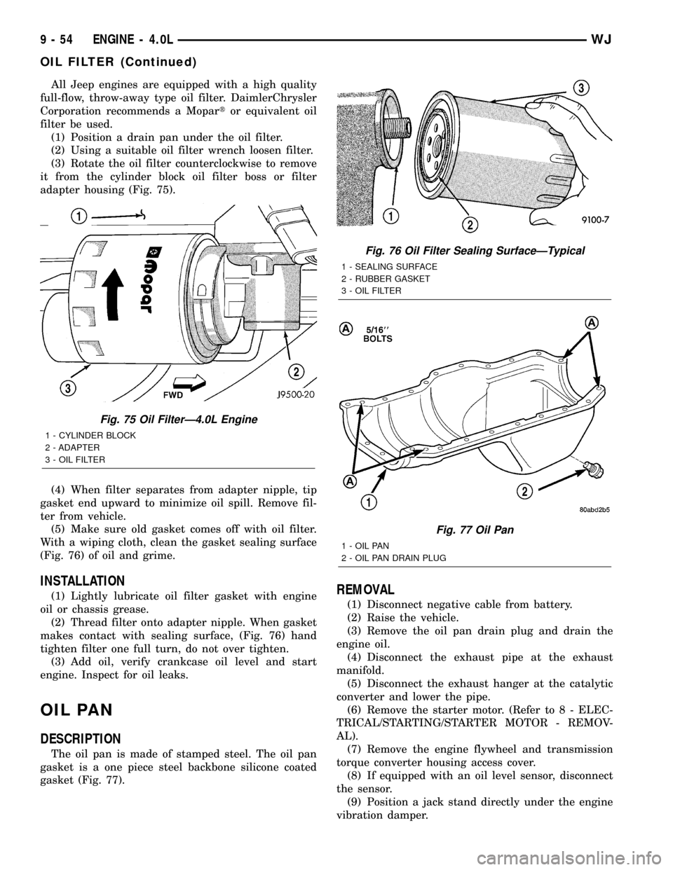
All Jeep engines are equipped with a high quality
full-flow, throw-away type oil filter. DaimlerChrysler
Corporation recommends a Mopartor equivalent oil
filter be used.
(1) Position a drain pan under the oil filter.
(2) Using a suitable oil filter wrench loosen filter.
(3) Rotate the oil filter counterclockwise to remove
it from the cylinder block oil filter boss or filter
adapter housing (Fig. 75).
(4) When filter separates from adapter nipple, tip
gasket end upward to minimize oil spill. Remove fil-
ter from vehicle.
(5) Make sure old gasket comes off with oil filter.
With a wiping cloth, clean the gasket sealing surface
(Fig. 76) of oil and grime.
INSTALLATION
(1) Lightly lubricate oil filter gasket with engine
oil or chassis grease.
(2) Thread filter onto adapter nipple. When gasket
makes contact with sealing surface, (Fig. 76) hand
tighten filter one full turn, do not over tighten.
(3) Add oil, verify crankcase oil level and start
engine. Inspect for oil leaks.
OIL PAN
DESCRIPTION
The oil pan is made of stamped steel. The oil pan
gasket is a one piece steel backbone silicone coated
gasket (Fig. 77).
REMOVAL
(1) Disconnect negative cable from battery.
(2) Raise the vehicle.
(3) Remove the oil pan drain plug and drain the
engine oil.
(4) Disconnect the exhaust pipe at the exhaust
manifold.
(5) Disconnect the exhaust hanger at the catalytic
converter and lower the pipe.
(6) Remove the starter motor. (Refer to 8 - ELEC-
TRICAL/STARTING/STARTER MOTOR - REMOV-
AL).
(7) Remove the engine flywheel and transmission
torque converter housing access cover.
(8) If equipped with an oil level sensor, disconnect
the sensor.
(9) Position a jack stand directly under the engine
vibration damper.
Fig. 75 Oil FilterÐ4.0L Engine
1 - CYLINDER BLOCK
2 - ADAPTER
3 - OIL FILTER
Fig. 76 Oil Filter Sealing SurfaceÐTypical
1 - SEALING SURFACE
2 - RUBBER GASKET
3 - OIL FILTER
Fig. 77 Oil Pan
1 - OIL PAN
2 - OIL PAN DRAIN PLUG
9 - 54 ENGINE - 4.0LWJ
OIL FILTER (Continued)
Page 1299 of 2199
(9) Lower the engine until it is properly located on
the engine mounts.
(10) Install the through bolts and tighten the nuts.
(11) Lower the jack stand and remove the piece of
wood.
(12) Install the engine flywheel and transmission
torque converter housing access cover.
(13) Install the engine starter motor. (Refer to 8 -
ELECTRICAL/STARTING/STARTER MOTOR -
INSTALLATION).
(14) Connect the exhaust pipe to the hanger and to
the engine exhaust manifold.
(15) Install transmission oil cooling lines (if
equipped) and oxygen sensor wiring supports that
attach to the oil pan studs.
(16) Install the oil pan drain plug (Fig. 81).
Tighten the plug to 34 N´m (25 ft. lbs.) torque.
(17) Lower the vehicle.
(18) Connect negative cable to battery.
(19) Fill the oil pan with engine oil to the specified
level.
WARNING: USE EXTREME CAUTION WHEN THE
ENGINE IS OPERATING. DO NOT STAND IN A
DIRECT LINE WITH THE FAN. DO NOT PUT YOUR
HANDS NEAR THE PULLEYS, BELTS OR FAN. DO
NOT WEAR LOOSE CLOTHING.
(20) Start the engine and inspect for leaks.
ENGINE OIL PRESSURE
SENSOR
DESCRIPTION
The 3±wire, solid-state engine oil pressure sensor
(sending unit) is located in an engine oil pressure
gallery.
OPERATION
The oil pressure sensor uses three circuits. They
are:
²A 5±volt power supply from the Powertrain Con-
trol Module (PCM)
²A sensor ground through the PCM's sensor
return
²A signal to the PCM relating to engine oil pres-
sure
The oil pressure sensor has a 3±wire electrical
function very much like the Manifold Absolute Pres-
sure (MAP) sensor. Meaning different pressures
relate to different output voltages.
A 5±volt supply is sent to the sensor from the PCM
to power up the sensor. The sensor returns a voltage
signal back to the PCM relating to engine oil pres-
sure. This signal is then transferred (bussed) to theinstrument panel on either a CCD or PCI bus circuit
(depending on vehicle line) to operate the oil pressure
gauge and the check gauges lamp. Ground for the
sensor is provided by the PCM through a low-noise
sensor return.
OIL PUMP
REMOVAL
A gear-type oil pump is mounted at the underside
of the cylinder block opposite the No.4 main bearing.
(1) Drain the engine oil.
(2) Remove the oil pan (Refer to 9 - ENGINE/LU-
BRICATION/OIL PAN - REMOVAL).
(3) Remove the pump-to-cylinder block attaching
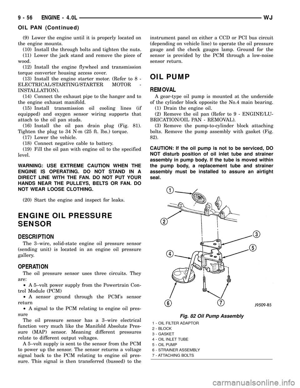
bolts. Remove the pump assembly with gasket (Fig.
82).
CAUTION: If the oil pump is not to be serviced, DO
NOT disturb position of oil inlet tube and strainer
assembly in pump body. If the tube is moved within
the pump body, a replacement tube and strainer
assembly must be installed to assure an airtight
seal.
Fig. 82 Oil Pump Assembly
1 - OIL FILTER ADAPTOR
2 - BLOCK
3 - GASKET
4 - OIL INLET TUBE
5 - OIL PUMP
6 - STRAINER ASSEMBLY
7 - ATTACHING BOLTS
9 - 56 ENGINE - 4.0LWJ
OIL PAN (Continued)
Page 1300 of 2199

INSTALLATION
A gear-type oil pump is mounted at the underside
of the cylinder block opposite the No.4 main bearing.
(1) Install the oil pump on the cylinder block using
a replacement gasket. Tighten the bolts to 23 N´m
(17 ft. lbs.) torque.
(2) Install the oil pan (Refer to 9 - ENGINE/LU-
BRICATION/OIL PAN - INSTALLATION).
(3) Fill the oil pan with oil to the specified level.
INTAKE MANIFOLD
DESCRIPTION
The intake manifold (Fig. 83) is made of cast alu-
minum and uses eleven bolts to mount to the cylin-
der head. This mounting style improves sealing and
reduces the chance of leaks.
DIAGNOSIS AND TESTING - INTAKE
MANIFOLD LEAKAGE
An intake manifold air leak is characterized by
lower than normal manifold vacuum. Also, one or
more cylinders may not be functioning.
WARNING: USE EXTREME CAUTION WHEN THE
ENGINE IS OPERATING. DO NOT STAND IN A
DIRECT LINE WITH THE FAN. DO NOT PUT YOUR
HANDS NEAR THE PULLEYS, BELTS OR THE FAN.
DO NOT WEAR LOOSE CLOTHING.
(1) Start the engine.
(2) Spray a small stream of water at the suspected
leak area.
(3) If a change in RPM is observed the area of the
suspected leak has been found.
(4) Repair as required.
REMOVAL
NOTE: THE ENGINE INTAKE AND EXHAUST MANI-
FOLD MUST BE REMOVED AND INSTALLED
TOGETHER. THE MANIFOLDS USE A COMMON
GASKET AT THE CYLINDER HEAD.
(1) Disconnect the battery negative cable.
(2) Remove air cleaner inlet hose from the resona-
tor assembly.
(3) Remove the air cleaner assembly.
(4) Remove the throttle cable, vehicle speed control
cable (if equipped) and the transmission line pres-
sure cable (Refer to 21 - TRANSMISSION/TRANS-
AXLE/AUTOMATIC - AW4/THROTTLE VALVE
CABLE - REMOVAL).
(5) Disconnect the following electrical connections
and secure their harness out of the way:
²Throttle Position Sensor
²Idle Air Control Motor
²Coolant Temperature Sensor (at thermostat
housing)
²Intake Air Temperature Sensor
²Oxygen Sensor
²Crank Position Sensor
²Six (6) Fuel Injector Connectors
²Manifold Absolute Pressure (MAP) Sensor.
(6) Disconnect HVAC, and Brake Booster vacuum
supply hoses at the intake manifold.
(7) Perform the fuel pressure release procedure.
(Refer to 14 - FUEL SYSTEM/FUEL DELIVERY -
STANDARD PROCEDURE).
(8) Disconnect and remove the fuel system supply
line from the fuel rail assembly.
(9) Remove the accessory drive belt (Refer to 7 -
COOLING/ACCESSORY DRIVE/DRIVE BELTS -
REMOVAL).
(10) Remove the power steering pump from the
intake manifold and set aside.
(11) Raise the vehicle.
(12) Disconnect the exhaust pipes from the engine
exhaust manifolds.
(13) Lower the vehicle.
(14) Remove the intake manifold and exhaust
manifold bolts and manifolds (Fig. 84).
INSTALLATION
If the manifold is being replaced, ensure all the fit-
ting, etc. are transferred to the replacement mani-
fold.
(1) Install a new engine exhaust/intake manifold
gasket over the alignment dowels on the cylinder
head.
(2) Position the engine exhaust manifolds to the
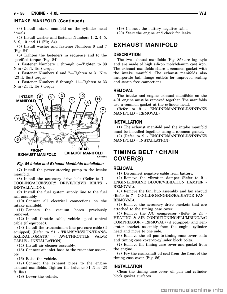
cylinder head. Install fastener Number 3 and finger
tighten at this time (Fig. 84).
Fig. 83 Intake Manifold 4.0L Engine
WJENGINE - 4.0L 9 - 57
OIL PUMP (Continued)
Page 1301 of 2199
(3) Install intake manifold on the cylinder head
dowels.
(4) Install washer and fastener Numbers 1, 2, 4, 5,
8, 9, 10 and 11 (Fig. 84).
(5) Install washer and fastener Numbers 6 and 7
(Fig. 84).
(6) Tighten the fasteners in sequence and to the
specified torque (Fig. 84).
²Fastener Numbers 1 through 5ÐTighten to 33
N´m (24 ft. lbs.) torque.
²Fastener Numbers 6 and 7ÐTighten to 31 N´m
(23 ft. lbs.) torque.
²Fastener Numbers 8 through 11ÐTighten to 33
N´m (24 ft. lbs.) torque.
(7) Install the power steering pump to the intake
manifold.
(8) Install the accessory drive belt (Refer to 7 -
COOLING/ACCESSORY DRIVE/DRIVE BELTS -
INSTALLATION).
(9) Install the fuel system supply line to the fuel
rail assembly.
(10) Connect all electrical connections on the
intake manifold.
(11) Connect the vacuum hoses previously
removed.
(12) Install throttle cable, vehicle speed control
cable (if equipped).
(13) Install the transmission line pressure cable (if
equipped) (Refer to 21 - TRANSMISSION/TRANS-
AXLE/AUTOMATIC - AW4/THROTTLE VALVE
CABLE - INSTALLATION).
(14) Install air cleaner assembly.
(15) Connect air inlet hose to the resonator assem-
bly.
(16) Raise the vehicle.
(17) Connect the exhaust pipes to the engine
exhaust manifolds. Tighten the bolts to 31 N´m (23
ft. lbs.)
(18) Lower the vehicle.(19) Connect the battery negative cable.
(20) Start the engine and check for leaks.
EXHAUST MANIFOLD
DESCRIPTION
The two exhaust manifolds (Fig. 85) are log style
and are made of high silicon molybdenum cast iron.
The exhaust manifolds share a common gasket with
the intake manifold. The exhaust manifolds also
incorporate ball flange outlets for improved sealing
and strain free connections.
REMOVAL
The intake and engine exhaust manifolds on the
4.0L engine must be removed together. The manifolds
use a common gasket at the cylinder head.
(Refer to 9 - ENGINE/MANIFOLDS/INTAKE
MANIFOLD - REMOVAL).
INSTALLATION
(1) The exhaust manifold and the intake manifold
must be installed together using a common gasket.
(2) (Refer to 9 - ENGINE/MANIFOLDS/INTAKE
MANIFOLD - INSTALLATION).
TIMING BELT / CHAIN
COVER(S)
REMOVAL
(1) Disconnect negative cable from battery.
(2) Remove the vibration damper (Refer to 9 -
ENGINE/ENGINE BLOCK/VIBRATION DAMPER -
REMOVAL).
(3) Remove the fan, hub assembly and fan shroud
(Refer to 7 - COOLING/ENGINE/RADIATOR FAN -
REMOVAL).
(4) Remove the accessory drive brackets that are
attached to the timing case cover.
(5) Remove the A/C compressor (Refer to 24 -
HEATING & AIR CONDITIONING/PLUMBING/A/C
COMPRESSOR - REMOVAL) (if equipped) and gen-
erator bracket assembly from the engine cylinder
head and move to one side.
(6) Remove the oil pan-to-timing case cover bolts
and timing case cover-to-cylinder block bolts.
(7) Remove the timing case cover and gasket from
the engine.
(8) Pry the crankshaft oil seal from the front of the
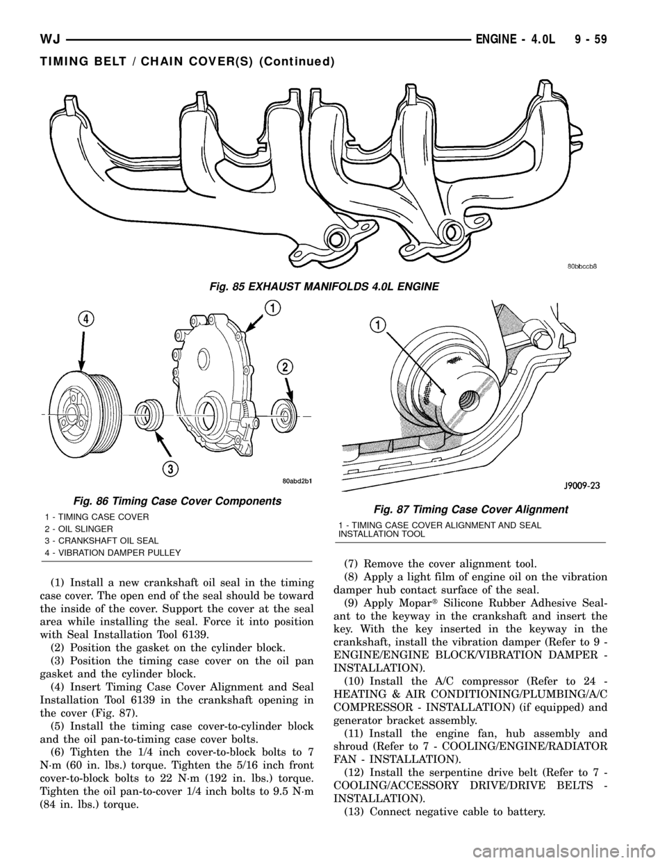
timing case cover (Fig. 86).
INSTALLATION
Clean the timing case cover, oil pan and cylinder
block gasket surfaces.
Fig. 84 Intake and Exhaust Manifolds Installation
9 - 58 ENGINE - 4.0LWJ
INTAKE MANIFOLD (Continued)
Page 1302 of 2199
(1) Install a new crankshaft oil seal in the timing
case cover. The open end of the seal should be toward
the inside of the cover. Support the cover at the seal
area while installing the seal. Force it into position
with Seal Installation Tool 6139.
(2) Position the gasket on the cylinder block.
(3) Position the timing case cover on the oil pan
gasket and the cylinder block.
(4) Insert Timing Case Cover Alignment and Seal
Installation Tool 6139 in the crankshaft opening in
the cover (Fig. 87).
(5) Install the timing case cover-to-cylinder block
and the oil pan-to-timing case cover bolts.
(6) Tighten the 1/4 inch cover-to-block bolts to 7
N´m (60 in. lbs.) torque. Tighten the 5/16 inch front
cover-to-block bolts to 22 N´m (192 in. lbs.) torque.
Tighten the oil pan-to-cover 1/4 inch bolts to 9.5 N´m
(84 in. lbs.) torque.(7) Remove the cover alignment tool.
(8) Apply a light film of engine oil on the vibration
damper hub contact surface of the seal.
(9) Apply MopartSilicone Rubber Adhesive Seal-
ant to the keyway in the crankshaft and insert the
key. With the key inserted in the keyway in the
crankshaft, install the vibration damper (Refer to 9 -
ENGINE/ENGINE BLOCK/VIBRATION DAMPER -
INSTALLATION).
(10) Install the A/C compressor (Refer to 24 -
HEATING & AIR CONDITIONING/PLUMBING/A/C
COMPRESSOR - INSTALLATION) (if equipped) and
generator bracket assembly.
(11) Install the engine fan, hub assembly and
shroud (Refer to 7 - COOLING/ENGINE/RADIATOR
FAN - INSTALLATION).
(12) Install the serpentine drive belt (Refer to 7 -
COOLING/ACCESSORY DRIVE/DRIVE BELTS -
INSTALLATION).
(13) Connect negative cable to battery.
Fig. 85 EXHAUST MANIFOLDS 4.0L ENGINE
Fig. 86 Timing Case Cover Components
1 - TIMING CASE COVER
2 - OIL SLINGER
3 - CRANKSHAFT OIL SEAL
4 - VIBRATION DAMPER PULLEYFig. 87 Timing Case Cover Alignment
1 - TIMING CASE COVER ALIGNMENT AND SEAL
INSTALLATION TOOL
WJENGINE - 4.0L 9 - 59
TIMING BELT / CHAIN COVER(S) (Continued)
Page 1303 of 2199
TIMING BELT/CHAIN AND
SPROCKETS
REMOVAL
(1) Disconnect negative cable from battery.
(2) Remove the fan and shroud (Refer to 7 -
COOLING/ENGINE/RADIATOR FAN - REMOVAL).
(3) Remove the serpentine drive belt (Refer to 7 -
COOLING/ACCESSORY DRIVE/DRIVE BELTS -
REMOVAL).
(4) Remove the crankshaft vibration damper (Refer
to 9 - ENGINE/ENGINE BLOCK/VIBRATION
DAMPER - REMOVAL).
(5) Remove the timing case cover (Refer to 9 -
ENGINE/VALVE TIMING/TIMING BELT / CHAIN
COVER(S) - REMOVAL).
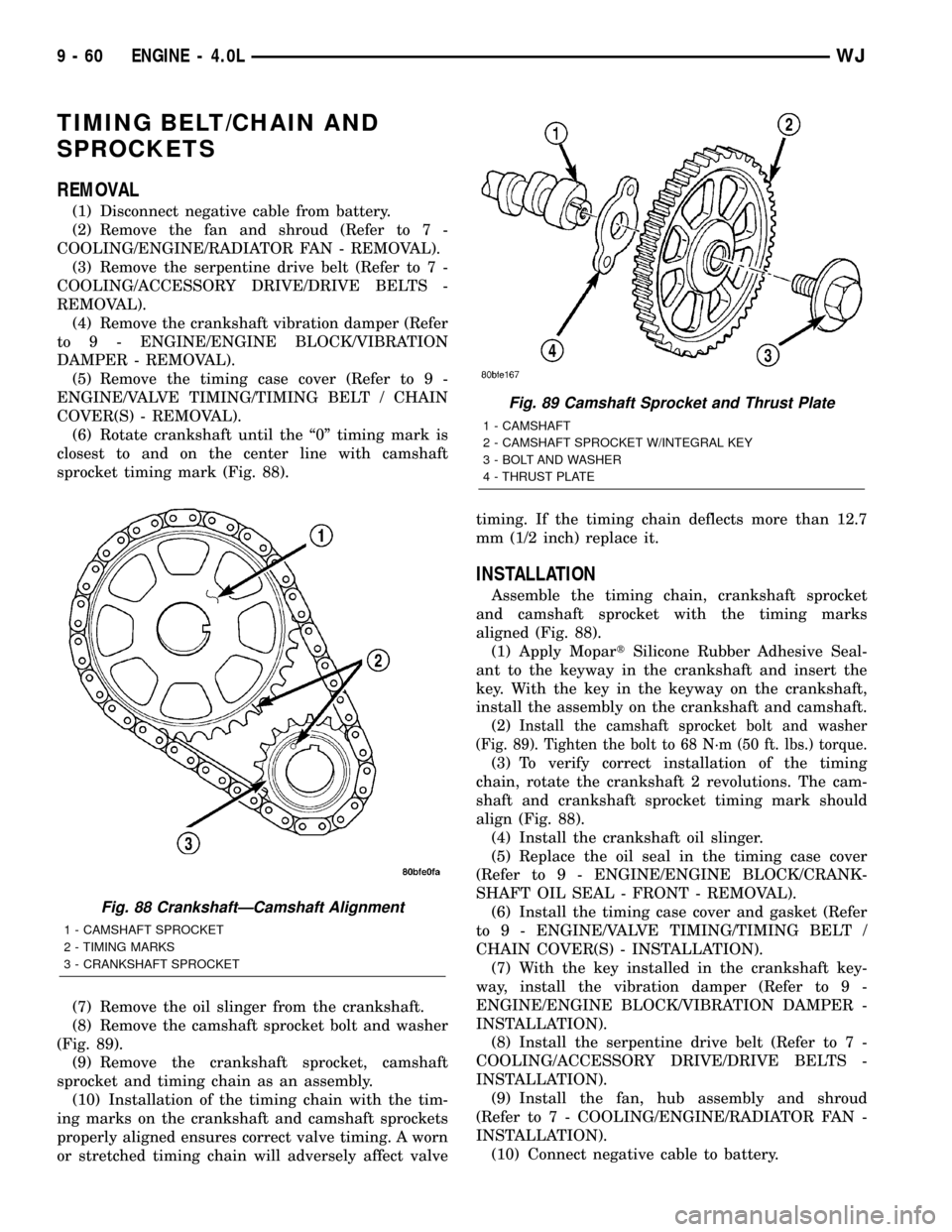
(6) Rotate crankshaft until the ª0º timing mark is
closest to and on the center line with camshaft
sprocket timing mark (Fig. 88).
(7) Remove the oil slinger from the crankshaft.
(8) Remove the camshaft sprocket bolt and washer
(Fig. 89).
(9) Remove the crankshaft sprocket, camshaft
sprocket and timing chain as an assembly.
(10) Installation of the timing chain with the tim-
ing marks on the crankshaft and camshaft sprockets
properly aligned ensures correct valve timing. A worn
or stretched timing chain will adversely affect valvetiming. If the timing chain deflects more than 12.7
mm (1/2 inch) replace it.
INSTALLATION
Assemble the timing chain, crankshaft sprocket
and camshaft sprocket with the timing marks
aligned (Fig. 88).
(1) Apply MopartSilicone Rubber Adhesive Seal-
ant to the keyway in the crankshaft and insert the
key. With the key in the keyway on the crankshaft,
install the assembly on the crankshaft and camshaft.
(2)
Install the camshaft sprocket bolt and washer
(Fig. 89). Tighten the bolt to 68 N´m (50 ft. lbs.) torque.
(3) To verify correct installation of the timing
chain, rotate the crankshaft 2 revolutions. The cam-
shaft and crankshaft sprocket timing mark should
align (Fig. 88).
(4) Install the crankshaft oil slinger.
(5) Replace the oil seal in the timing case cover
(Refer to 9 - ENGINE/ENGINE BLOCK/CRANK-
SHAFT OIL SEAL - FRONT - REMOVAL).
(6) Install the timing case cover and gasket (Refer
to 9 - ENGINE/VALVE TIMING/TIMING BELT /
CHAIN COVER(S) - INSTALLATION).
(7) With the key installed in the crankshaft key-
way, install the vibration damper (Refer to 9 -
ENGINE/ENGINE BLOCK/VIBRATION DAMPER -
INSTALLATION).
(8) Install the serpentine drive belt (Refer to 7 -
COOLING/ACCESSORY DRIVE/DRIVE BELTS -
INSTALLATION).
(9) Install the fan, hub assembly and shroud
(Refer to 7 - COOLING/ENGINE/RADIATOR FAN -
INSTALLATION).
(10) Connect negative cable to battery.
Fig. 88 CrankshaftÐCamshaft Alignment
1 - CAMSHAFT SPROCKET
2 - TIMING MARKS
3 - CRANKSHAFT SPROCKET
Fig. 89 Camshaft Sprocket and Thrust Plate
1 - CAMSHAFT
2 - CAMSHAFT SPROCKET W/INTEGRAL KEY
3 - BOLT AND WASHER
4 - THRUST PLATE
9 - 60 ENGINE - 4.0LWJ
Page 1314 of 2199
²Abrasive pad or paper to clean cylinder block
and head
²High speed power tool with an abrasive pad or a
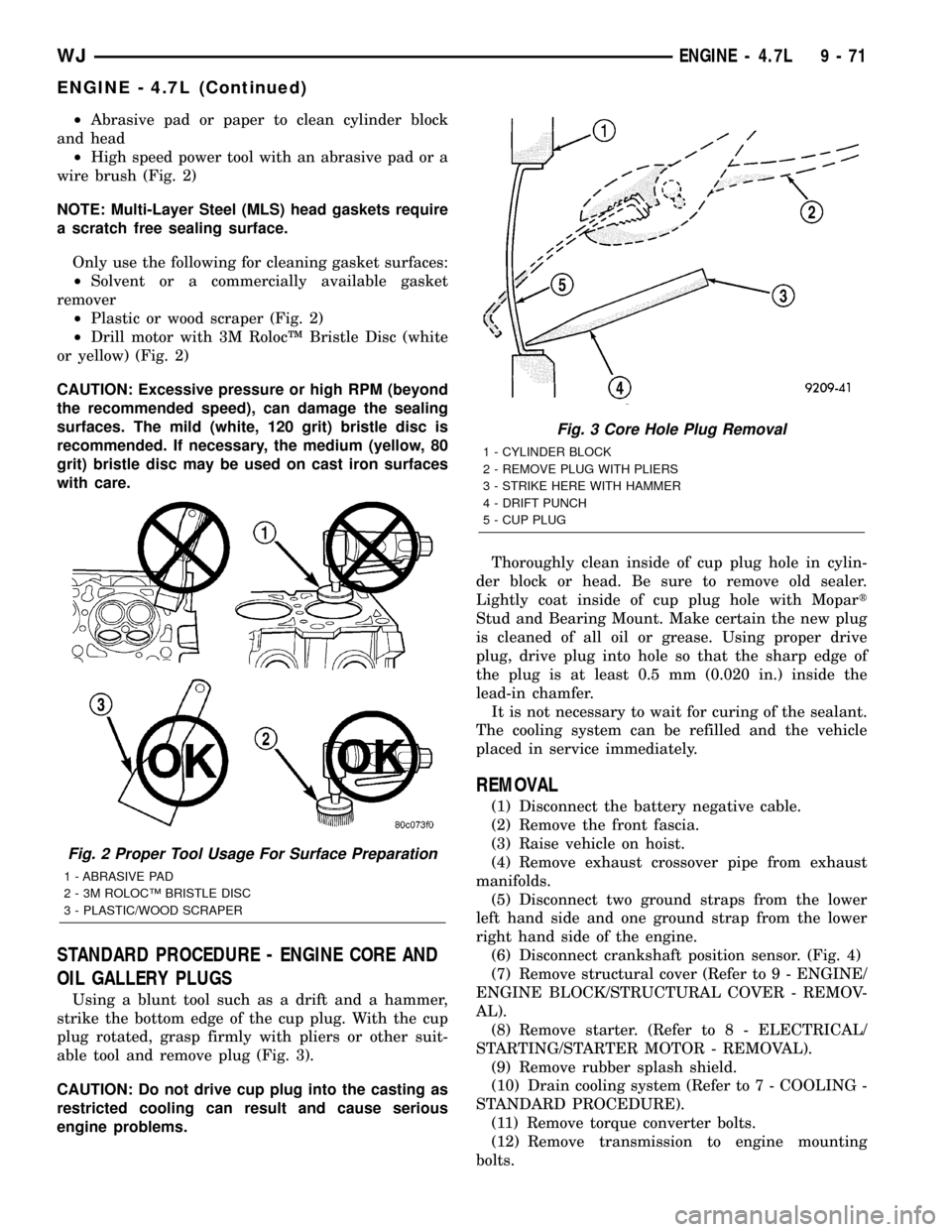
wire brush (Fig. 2)
NOTE: Multi-Layer Steel (MLS) head gaskets require
a scratch free sealing surface.
Only use the following for cleaning gasket surfaces:
²Solvent or a commercially available gasket
remover
²Plastic or wood scraper (Fig. 2)
²Drill motor with 3M RolocŸ Bristle Disc (white
or yellow) (Fig. 2)
CAUTION: Excessive pressure or high RPM (beyond
the recommended speed), can damage the sealing
surfaces. The mild (white, 120 grit) bristle disc is
recommended. If necessary, the medium (yellow, 80
grit) bristle disc may be used on cast iron surfaces
with care.
STANDARD PROCEDURE - ENGINE CORE AND
OIL GALLERY PLUGS
Using a blunt tool such as a drift and a hammer,
strike the bottom edge of the cup plug. With the cup
plug rotated, grasp firmly with pliers or other suit-
able tool and remove plug (Fig. 3).
CAUTION: Do not drive cup plug into the casting as
restricted cooling can result and cause serious
engine problems.Thoroughly clean inside of cup plug hole in cylin-
der block or head. Be sure to remove old sealer.
Lightly coat inside of cup plug hole with Mopart
Stud and Bearing Mount. Make certain the new plug
is cleaned of all oil or grease. Using proper drive
plug, drive plug into hole so that the sharp edge of
the plug is at least 0.5 mm (0.020 in.) inside the
lead-in chamfer.
It is not necessary to wait for curing of the sealant.
The cooling system can be refilled and the vehicle
placed in service immediately.
REMOVAL
(1) Disconnect the battery negative cable.
(2) Remove the front fascia.
(3) Raise vehicle on hoist.
(4) Remove exhaust crossover pipe from exhaust
manifolds.
(5) Disconnect two ground straps from the lower
left hand side and one ground strap from the lower
right hand side of the engine.
(6) Disconnect crankshaft position sensor. (Fig. 4)
(7) Remove structural cover (Refer to 9 - ENGINE/
ENGINE BLOCK/STRUCTURAL COVER - REMOV-
AL).
(8) Remove starter. (Refer to 8 - ELECTRICAL/
STARTING/STARTER MOTOR - REMOVAL).
(9) Remove rubber splash shield.
(10) Drain cooling system (Refer to 7 - COOLING -
STANDARD PROCEDURE).
(11) Remove torque converter bolts.
(12) Remove transmission to engine mounting
bolts.
Fig. 2 Proper Tool Usage For Surface Preparation
1 - ABRASIVE PAD
2 - 3M ROLOCŸ BRISTLE DISC
3 - PLASTIC/WOOD SCRAPER
Fig. 3 Core Hole Plug Removal
1 - CYLINDER BLOCK
2 - REMOVE PLUG WITH PLIERS
3 - STRIKE HERE WITH HAMMER
4 - DRIFT PUNCH
5 - CUP PLUG
WJENGINE - 4.7L 9 - 71
ENGINE - 4.7L (Continued)
Page 1315 of 2199

(13) Disconnect the engine block heater power
cable from the block heater.
(14) Lower vehicle.
(15) Remove throttle body resonator assembly and
inlet hose.
(16) Disconnect throttle and speed control cables.
(17) Disconnect tube from both the left and right
side crankcase breathers, then remove the breathers
(Fig. 5).
(18) Discharge A/C system (Refer to 24 - HEAT-
ING & AIR CONDITIONING/PLUMBING - STAN-
DARD PROCEDURE).(19) Remove radiator fan (Refer to 7 - COOLING/
ENGINE/RADIATOR FAN - REMOVAL) and acces-
sory drive belt (Refer to 7 - COOLING/ACCESSORY
DRIVE/DRIVE BELTS - REMOVAL).
(20) Remove A/C compressor (Refer to 24 - HEAT-
ING & AIR CONDITIONING/PLUMBING/A/C COM-
PRESSOR - REMOVAL).
(21) Disconnect transmission oil cooler lines at the
radiator.
(22) Disconnect radiator lower hose at the thermo-
stat housing.
(23) Remove A/C condenser (Refer to 24 - HEAT-
ING & AIR CONDITIONING/PLUMBING/A/C CON-
DENSER - REMOVAL).
(24) Remove radiator (Refer to 7 - COOLING/EN-
GINE/RADIATOR - REMOVAL).
(25) Remove generator (Refer to 8 - ELECTRICAL/
CHARGING/GENERATOR - REMOVAL).
(26) Disconnect the two heater hoses from the tim-
ing chain cover.
(27) Disconnect engine harness at the following
points :
²Intake air temperature (IAT) sensor (Fig. 6)
²Fuel Injectors
²Throttle Position (TPS) Switch
²Idle Air Control (IAC) Motor
²Engine Oil Pressure Switch
²Engine Coolant Temperature (ECT) Sensor
²Manifold absolute pressure (MAP) Sensor
²Camshaft Position (CMP) Sensor
²Coil Over Plugs
(28) Release fuel rail pressure (Refer to 14 - FUEL
SYSTEM/FUEL DELIVERY - STANDARD PROCE-
DURE) then disconnect the fuel supply quick connect
fitting at the fuel rail (Refer to 14 - FUEL SYSTEM/
FUEL DELIVERY/QUICK CONNECT FITTING -
STANDARD PROCEDURE).
(29) Remove power steering pump and position out
of the way.
(30) Disconnect ground straps from the left side of
the engine.
(31) Install Engine Lifting Fixture Special Tool
8347 (Fig. 7)following these steps.
²Holding the lifting fixture at a slight angle, slide
the large bore in the front plate over the hex portion
of the lifting stud.
²Position the two remaining fixture arms onto
the two lifting studs in the cylinder heads.
²Pull foward and upward on the lifting fixture so
that the lifting stud rest in the slotted area below the
large bore.
²Secure the lifting fixture to the three studs
using three 7/16 ± 14 N/C locknuts.
²Make sure the lifting loop in the lifting fixture is
in the last hole (closest to the throttle body) to min-
imize the angle of engine during removal.
Fig. 4 Crankshaft Position Sensor
1 - CRANKSHAFT POSITION SENSOR
2 - CYLINDER HEAD COVER
3 - CAMSHAFT POSITION SENSOR
4 - RIGHT SIDE CYLINDER BLOCK
Fig. 5 Crankcase Breather Connection Points
1 - CRANKCASE BREATHERS
9 - 72 ENGINE - 4.7LWJ
ENGINE - 4.7L (Continued)
Page 1317 of 2199
²Camshaft Position (CMP) Sensor
²Coil Over Plugs
(10) Install generator (Refer to 8 - ELECTRICAL/
CHARGING/GENERATOR - INSTALLATION).
(11) Install radiator (Refer to 7 - COOLING/EN-
GINE/RADIATOR - INSTALLATION).
(12) Install A/C condenser (Refer to 24 - HEATING
& AIR CONDITIONING/PLUMBING/A/C CON-
DENSER - INSTALLATION).
(13) Connect radiator lower hose at the thermostat
housing.
(14) Connect the transmission oil cooler lines to
the radiator.
(15) Install A/C compressor. (Refer to 24 - HEAT-
ING & AIR CONDITIONING/PLUMBING/A/C COM-
PRESSOR - INSTALLATION).
(16) Install accessory drive belt (Refer to 7 -
COOLING/ACCESSORY DRIVE/DRIVE BELTS -
INSTALLATION) and radiator fan (Refer to 7 -
COOLING/ENGINE/RADIATOR FAN - INSTALLA-
TION).
(17) Install breathers, then connect tube to both
crankcase breathers (Fig. 5).
(18) Connect throttle and speed control cables.
(19) Install throttle body resonator assembly and
inlet hose.
(20) Raise vehicle.
(21) Connect two ground straps on the lower left
hand side of the engine and one ground strap on the
lower right side.
(22) Install torque converter bolts.
(23) Connect crankshaft position sensor (Fig. 4).
(24) Install starter.
(25) Install rubber splash shield.
CAUTION: The structural cover requires a specific
torque sequence. Failure to follow this sequence
may cause severe damage to the cover.
(26) Install structural cover (Refer to 9 - ENGINE/
ENGINE BLOCK/STRUCTURAL COVER - INSTAL-
LATION).
(27) Install exhaust crossover pipe.
(28) Install engine block heater power cable, If
equipped.
(29) Lower vehicle.
(30) Check and fill engine oil (Refer to LUBRICA-
TION & MAINTENANCE/FLUID TYPES - SPECIFI-
CATIONS).
(31) Recharge the A/C system (Refer to 24 - HEAT-
ING & AIR CONDITIONING/PLUMBING - STAN-
DARD PROCEDURE).
(32) Refill the engine cooling system (Refer to 7 -
COOLING - STANDARD PROCEDURE).
(33) Connect the battery negative cable.
(34) Start engine and check for leaks.SPECIFICATIONS
4.7L ENGINE
DESCRIPTION SPECIFICATION
GENERAL SPECIFICATIONS
Engine Type 90É SOHC V-8 16-Valve
Displacement 4.7 Liters / 4701cc
(287 Cubic Inches)
Bore 93.0 mm (3.66 in.)
Stroke 86.5 mm (3.40 in.)
Compression Ratio 9.0:1
Horsepower 235 BHP @ 4800 RPM
Torque 295 LB-FT @ 3200 RPM
Lead Cylinder #1 Left Bank
Firing Order 1-8-4-3-6-5-7-2
CYLINDER BLOCK
Cylinder Block Cast Iron
Bore Diameter 93.010 .0075 mm
(3.6619 0.0003 in.)
Out of Round (MAX) 0.076 mm (0.003 in.)
Taper (MAX) 0.051 mm (0.002 in.)
PISTONS
Material Aluminum Alloy
Diameter 92.975 mm (3.6605 in.)
Weight 367.5 grams (12.96 oz)
Ring Groove Diameter
No. 1 83.73 - 83.97 mm
(3.296 - 3.269 in.)
No. 2 82.833 - 83.033 mm
(3.261 - 3.310 in.)
No. 3 83.88 - 84.08 mm
(3.302 - 3.310 in.)
PISTON PINS
Type Pressed Fit
Clearance In Piston 0.010 - 0.019 mm
(0.0004 - 0.0008 in.)
Diameter 24.013 - 24.016 mm
(0.9454 - 0.9456 in.)
9 - 74 ENGINE - 4.7LWJ
ENGINE - 4.7L (Continued)
Page 1328 of 2199
(3) Turn engine off and let set for a few minutes
before restarting. Repeat this several times after
engine has reached normal operating temperature.
(4) Low oil pressure.
(5) The oil restrictor in cylinder head gasket or the
oil passage to the cylinder head is plugged with
debris.
(6) Air ingested into oil due to broken or cracked
oil pump pick up.
(7) Worn valve guides.
(8) Rocker arm ears contacting valve spring
retainer.
(9) Rocker arm loose, adjuster stuck or at maxi-
mum extension and still leaves lash in the system.
(10) Oil leak or excessive cam bore wear in cylin-
der head.
(11) Faulty lash adjuster.
a. Check lash adjusters for sponginess while
installed in cylinder head and cam on camshaft at
base circle. Depress part of rocker arm over adjuster.
Normal adjusters should feel very firm. Spongy
adjusters can be bottomed out easily.
b. Remove suspected lash adjusters, and replace.
c. Before installation, make sure adjusters are at
least partially full of oil. This can be verified by little
or no plunger travel when lash adjuster is depressed.
DIAGNOSIS AND TESTINGÐCYLINDER HEAD
GASKET
A cylinder head gasket leak can be located between
adjacent cylinders or between a cylinder and the
adjacent water jacket.
Possible indications of the cylinder head gasket
leaking between adjacent cylinders are:
²Loss of engine power
²Engine misfiring
²Poor fuel economy
Possible indications of the cylinder head gasket
leaking between a cylinder and an adjacent water
jacket are:
²Engine overheating
²Loss of coolant
²Excessive steam (white smoke) emitting from
exhaust
²Coolant foaming
CYLINDER-TO-CYLINDER LEAKAGE TEST
To determine if an engine cylinder head gasket is
leaking between adjacent cylinders, follow the proce-
dures in Cylinder Compression Pressure Test (Refer
to 9 - ENGINE - DIAGNOSIS AND TESTING). An
engine cylinder head gasket leaking between adja-
cent cylinders will result in approximately a 50±70%
reduction in compression pressure.
CYLINDER-TO-WATER JACKET LEAKAGE TEST
WARNING: USE EXTREME CAUTION WHEN THE
ENGINE IS OPERATING WITH COOLANT PRES-
SURE CAP REMOVED.
VISUAL TEST METHOD
With the engine cool, remove the coolant pressure
cap. Start the engine and allow it to warm up until
thermostat opens.
If a large combustion/compression pressure leak
exists, bubbles will be visible in the coolant.
COOLING SYSTEM TESTER METHOD
WARNING: WITH COOLING SYSTEM TESTER IN
PLACE, PRESSURE WILL BUILD UP FAST. EXCES-
SIVE PRESSURE BUILT UP, BY CONTINUOUS
ENGINE OPERATION, MUST BE RELEASED TO A
SAFE PRESSURE POINT. NEVER PERMIT PRES-
SURE TO EXCEED 138 kPa (20 psi).
Install Cooling System Tester 7700 or equivalent to
pressure cap neck. Start the engine and observe the
tester's pressure gauge. If gauge pulsates with every
power stroke of a cylinder a combustion pressure
leak is evident.
CHEMICAL TEST METHOD
Combustion leaks into the cooling system can also
be checked by using Bloc-Chek Kit C-3685-A or
equivalent. Perform test following the procedures
supplied with the tool kit.
REMOVAL
(1) Disconnect the negative cable from the battery.
(2) Raise the vehicle on a hoist.
(3) Disconnect the exhaust pipe at the left side
exhaust manifold.
(4) Drain the engine coolant. (Refer to 7 - COOL-
ING - STANDARD PROCEDURE).
(5) Lower the vehicle.
(6) Remove the intake manifold. (Refer to 9 -
ENGINE/MANIFOLDS/INTAKE MANIFOLD -
REMOVAL).
(7) Remove the cylinder head cover. (Refer to 9 -
ENGINE/CYLINDER HEAD/CYLINDER HEAD
COVER(S) - REMOVAL).
(8) Remove accessory drive belt. (Refer to 7 -
COOLING/ACCESSORY DRIVE/DRIVE BELTS -
REMOVAL).
(9) Remove the power steering pump and set
aside.
(10) Rotate the crankshaft until the damper tim-
ing mark is aligned with TDC indicator mark (Fig.
9).
WJENGINE - 4.7L 9 - 85
CYLINDER HEAD - LEFT (Continued)