Antenna JEEP GRAND CHEROKEE 2002 WJ / 2.G Owner's Manual
[x] Cancel search | Manufacturer: JEEP, Model Year: 2002, Model line: GRAND CHEROKEE, Model: JEEP GRAND CHEROKEE 2002 WJ / 2.GPages: 2199, PDF Size: 76.01 MB
Page 606 of 2199

cluster circuitry that controls the lamp, (Refer to 8 -
ELECTRICAL/INSTRUMENT CLUSTER - DIAGNO-
SIS AND TESTING). If the instrument cluster turns
on the SKIS indicator lamp after the bulb test, either
solid or flashing, it indicates that a SKIS malfunction
has occurred or that the SKIS is inoperative. For
proper diagnosis of the SKIS, the PCI data bus, or
the message inputs to the instrument cluster that
control the SKIS indicator lamp, a DRBIIItscan tool
and the appropriate diagnostic information are
required.
TRANSPONDER KEY
DESCRIPTION
Each ignition key used in the Sentry Key Immobi-
lizer System (SKIS) has an integral transponder chip
(Fig. 10). Ignition keys with this feature can be
readily identified by a gray rubber cap molded onto
the head of the key, while conventional ignition keys
have a black molded rubber cap. The transponder
chip is concealed beneath the molded rubber cap,
where it is molded into the head of the metal key.
Each new Sentry Key has a unique transponder iden-
tification code permanently programmed into it by
the manufacturer. The Sentry Key transponder if
faulty or damaged, must be replaced.
OPERATION
When the ignition switch is turned to the On posi-
tion, the Sentry Key Immobilizer Module (SKIM)communicates through its antenna with the Sentry
Key transponder using a Radio Frequency (RF) sig-
nal. The SKIM then waits for a RF response from the
transponder through the same antenna. The Sentry
Key transponder chip is within the range of the
SKIM transceiver antenna ring when it is inserted
into the ignition lock cylinder. The SKIM determines
whether a valid key is present in the ignition lock
cylinder based upon the response from the transpon-
der. If a valid key is detected, that fact is communi-
cated by the SKIM to the Powertrain Control Module
(PCM) over the Programmable Communications
Interface (PCI) data bus, and the PCM allows the
engine to continue running. If the PCM receives an
invalid key message, or receives no message from the
SKIM over the PCI data bus, the engine will be dis-
abled after about two seconds of operation. The Elec-
troMechanical Instrument Cluster (EMIC) will also
respond to the invalid key message on the PCI data
bus by flashing the SKIS indicator on and off.
Each Sentry Key has a unique transponder identi-
fication code permanently programmed into it by the
manufacturer. Likewise, the SKIM has a unique
Secret Key code programmed into it by the manufac-
turer. When a Sentry Key is programmed into the
memory of the SKIM, the SKIM stores the transpon-
der identification code from the Sentry Key, and the
Sentry Key learns the Secret Key code from the
SKIM. Once the Sentry Key learns the Secret Key
code of the SKIM, it is permanently stored in the
memory of the transponder. Therefore, once a Sentry
Key has been programmed to a particular vehicle, it
cannot be used on any other vehicle. (Refer to 8 -
ELECTRICAL/VEHICLE THEFT SECURITY -
STANDARD PROCEDURE - TRANSPONDER PRO-
GRAMMING).
VTSS INDICATOR
DESCRIPTION
The Vehicle Theft Security System (VTSS) indica-
tor consists of a red Light-Emitting Diode that is
mounted and integral to the automatic headlamp
light sensor photo diode unit, which is located on the
top of the instrument panel. The remainder of the
housing including the mount and the electrical con-
nection are concealed beneath the instrument panel
top cover.
The VTSS indicator cannot be adjusted or repaired
the entire automatic headlamp light sensor/VTSS
indicator must be replaced. (Refer to 8 - ELECTRI-
CAL/LAMPS/LIGHTING - EXTERIOR/AUTO HEAD-
LAMP SENSOR - REMOVAL).
Fig. 10 Sentry Key Immobilizer Transponder
1 - MOLDED CAP
2 - TRANSPONDER CHIP
3 - MOLDED CAP REMOVED
4 - TRANSPONDER KEY
WJVEHICLE THEFT SECURITY 8Q - 15
SKIS INDICATOR LAMP (Continued)
Page 672 of 2199

8W-02 COMPONENT INDEX
Component Page
A/C Compressor Clutch................. 8W-42
A/C Pressure Transducer................ 8W-42
Accelerator Pedal Position Sensor......... 8W-30
Accessory Delay Relay.................. 8W-64
Adjustable Pedals..................... 8W-30
Airbags............................. 8W-43
Ambient Temperature Sensor............ 8W-45
Antennas............................ 8W-47
Ash Receiver Lamp.................... 8W-44
Auto Shut Down Relay................. 8W-30
Automatic Day/Night Mirror............. 8W-49
Automatic Headlamp Light Sensor/VTSS
LED.............................. 8W-39
Automatic Zone Control Module.......... 8W-42
Back-Up Lamp Relay................... 8W-51
Battery Temperature Sensor............. 8W-30
Battery............................. 8W-20
Blend Door Motor/Actuator.............. 8W-42
Blower Motor......................... 8W-42
Body Control Module................... 8W-45
Boost Pressure Sensor.................. 8W-30
Brake Lamp Switch.................... 8W-33
Camshaft Position Sensor............... 8W-30
Capacitors........................... 8W-30
Cargo Lamp.......................... 8W-44
Center High Mounted Stop Lamp......... 8W-51
Cigar Lighter......................... 8W-41
Circuit Breakers...................... 8W-12
Clockspring.................. 8W-33, 41, 43, 47
Coil On Plugs......................... 8W-30
Coil Rail............................. 8W-30
Combination Flasher................... 8W-52
Compact Disc Changer.................. 8W-47
Controller Antilock Brake............... 8W-35
Coolant Level Sensor................... 8W-45
Courtesy Lamps....................... 8W-44
Crankcase Heater..................... 8W-30
Crankshaft Position Sensor.............. 8W-30
Cylinder Lock Switches................. 8W-61
Data Link Connector................... 8W-18
Diagnostic Junction Port................ 8W-18
EGR Solenoid......................... 8W-30
Electric Brake........................ 8W-54
Electronic Speed Control Servo........... 8W-33
Engine Control Module................. 8W-30
Engine Coolant Temperature Sensor...... 8W-30
Engine Oil Pressure Sensor.............. 8W-30
Engine Starter Motor................... 8W-21
EVAP/Purge Solenoid................... 8W-30
Fog Lamps........................ 8W-50, 51
Fuel Injectors......................... 8W-30
Fuel Pressure Sensor................... 8W-30Component Page
Fuel Pressure Solenoid................. 8W-30
Fuel Pump........................... 8W-30
Fuel Tank Module..................... 8W-30
Fuses............................ 8W-10, 12
Fusible Link....................... 8W-10, 20
Grounds............................. 8W-15
Generator......................... 8W-20, 30
Glove Box Lamp...................... 8W-44
Glow Plugs........................... 8W-30
Headlamp Leveling Motor............... 8W-50
Heated Seats......................... 8W-63
High Beam Headlamps................. 8W-50
Hood Ajar Switch...................... 8W-39
Horns............................... 8W-41
Hydraulic Cooling Module............ 8W-30, 42
Idle Air Control Motor.................. 8W-30
Ignition Switch....................... 8W-10
Impact Sensors....................... 8W-43
Input Speed Sensor.................... 8W-31
Instrument Cluster.................... 8W-40
Intake Air Temperature Sensor........... 8W-30
Intake Port Swirl Actuator.............. 8W-30
Intrusion Transceiver Module............ 8W-49
Junction Block........................ 8W-12
Knock Sensor......................... 8W-30
Lamp Assemblies................... 8W-51, 52
Leak Detection Pump.................. 8W-30
License Lamps........................ 8W-51
Liftgate............................. 8W-61
Line Pressure Sensor................... 8W-31
Low Beam Headlamps.................. 8W-50
Low Beam Relay...................... 8W-50
Low Beam/Daytime Running Lamp Relay . . . 8W-50
Lumbar Motor........................ 8W-63
Lumbar Switch....................... 8W-63
Manifold Absolute Pressure Sensor........ 8W-30
Manual Temperature Control............. 8W-42
Mass Air Flow Sensor.................. 8W-30
Memory Set Switch................. 8W-62, 63
Mode Door Motor/Actuator............... 8W-42
Multi-Function Switch............... 8W-50, 53
Output Speed Sensor................... 8W-31
Overhead Map/Courtesy Lamp........... 8W-44
Oxygen Sensors....................... 8W-30
Park Brake Switch..................... 8W-40
Park Lamp........................... 8W-50
Park/Neutral Position Switch............ 8W-31
Park/Turn Signal Lamps................ 8W-50
Power Amplifier....................... 8W-47
Power Connector...................... 8W-41
Power Distribution Center............... 8W-10
Power Mirrors........................ 8W-62
WJ8W-02 COMPONENT INDEX 8W - 02 - 1
Page 932 of 2199

8W-47 AUDIO SYSTEM
Component Page
Antenna........................... 8W-47-2
Antenna Module..................... 8W-47-3
Body Control Module............. 8W-47-2, 3, 13
Clockspring........................ 8W-47-13
Compact Disc Changer.............. 8W-47-6, 7
Diagnostic Junction Port...... 8W-47-2, 3, 6, 7, 13
Fuse 5........................... 8W-47-2, 3
Fuse 30.......................... 8W-47-2, 3
G300............................ 8W-47-2, 3
Junction Block.................... 8W-47-2, 3Component Page
Left Front Door Speaker......... 8W-47-4, 10, 11
Left Instrument Panel Speaker....... 8W-47-4, 12
Left Rear Door Speaker.......... 8W-47-5, 10, 11
Left Remote Radio Switch............. 8W-47-13
Power Amplifier..... 8W-47-3, 6, 7, 8, 9, 10, 11, 12
Radio............. 8W-47-2, 3, 4, 5, 6, 7, 8, 9, 13
Right Front Door Speaker........ 8W-47-4, 10, 11
Right Instrument Panel Speaker..... 8W-47-4, 12
Right Rear Door Speaker......... 8W-47-5, 10, 11
Right Remote Radio Switch........... 8W-47-13
WJ8W-47 AUDIO SYSTEM 8W - 47 - 1
Page 1048 of 2199

8W-80 CONNECTOR PIN-OUT
Component Page
A/C COMPRESSOR CLUTCH.......... 8W-80-6
A/C PRESSURE TRANSDUCER........ 8W-80-6
ACCELERATOR PEDAL POSITION
SENSOR (DIESEL)................. 8W-80-6
ADJUSTABLE PEDALS MODULE
(EXCEPT BUILT-UP-EXPORT)....... 8W-80-6
ADJUSTABLE PEDALS MOTOR/SENSOR
ASSEMBLY (EXCEPT
BUILT-UP-EXPORT)............... 8W-80-7
ADJUSTABLE PEDALS SWITCH (EXCEPT
BUILT-UP-EXPORT)............... 8W-80-7
AIRBAG CONTROL MODULE C1
(ORC C1)........................ 8W-80-7
AIRBAG CONTROL MODULE C2
(ORC C2)........................ 8W-80-8
AMBIENT TEMPERATURE SENSOR.... 8W-80-8
ANTENNA MODULE
(BUILT-UP-EXPORT)............... 8W-80-8
ASH RECEIVER LAMP............... 8W-80-9
AUTOMATIC DAY/NIGHT MIRROR..... 8W-80-9
AUTOMATIC HEADLAMP LIGHT
SENSOR/VTSS LED................ 8W-80-9
AUTOMATIC ZONE CONTROL
MODULE C1 (AZC)................ 8W-80-9
AUTOMATIC ZONE CONTROL
MODULE C2 (AZC)............... 8W-80-10
BATTERY TEMPERATURE SENSOR . . . 8W-80-10
BLOWER MOTOR.................. 8W-80-10
BLOWER MOTOR CONTROLLER
(AZC).......................... 8W-80-10
BLOWER MOTOR RESISTOR
BLOCK (MTC)................... 8W-80-10
BODY CONTROL MODULE C1........ 8W-80-11
BODY CONTROL MODULE C2........ 8W-80-11
BOOST PRESSURE SENSOR
(DIESEL)....................... 8W-80-12
BRAKE LAMP SWITCH.............. 8W-80-12
C100............................. 8W-80-12
C100............................. 8W-80-12
C101 (4.0L RHD)................... 8W-80-12
C101 (4.0L RHD)................... 8W-80-13
C101 (4.7L RHD)................... 8W-80-13
C101 (4.7L RHD)................... 8W-80-13
C102 (DIESEL)..................... 8W-80-14
C102 (DIESEL)..................... 8W-80-14
C102 (GAS RHD)................... 8W-80-14
C102 (GAS RHD)................... 8W-80-15
C103 (DIESEL)..................... 8W-80-15
C103 (DIESEL)..................... 8W-80-15
C103 (GAS)........................ 8W-80-16
C103 (GAS)........................ 8W-80-16
C104............................. 8W-80-17
C104............................. 8W-80-17Component Page
C105 (DIESEL)..................... 8W-80-17
C105 (DIESEL)..................... 8W-80-18
C106 (DIESEL)..................... 8W-80-18
C106 (DIESEL)..................... 8W-80-20
C106 (GAS)........................ 8W-80-22
C106 (GAS)........................ 8W-80-24
C107 (DIESEL)..................... 8W-80-26
C107 (DIESEL)..................... 8W-80-28
C107 (GAS)........................ 8W-80-30
C107 (GAS)........................ 8W-80-32
C108............................. 8W-80-33
C108............................. 8W-80-33
C109............................. 8W-80-33
C109............................. 8W-80-34
C110 (DIESEL)..................... 8W-80-34
C110 (DIESEL)..................... 8W-80-34
C111 ............................. 8W-80-34
C111 ............................. 8W-80-34
C112 ............................. 8W-80-35
C112 ............................. 8W-80-35
C113 (DIESEL)..................... 8W-80-35
C113 (DIESEL)..................... 8W-80-35
C200............................. 8W-80-36
C200............................. 8W-80-38
C201 (DIESEL)..................... 8W-80-39
C201 (DIESEL)..................... 8W-80-39
C202 (AZC)........................ 8W-80-40
C202 (AZC)........................ 8W-80-40
C202 (MTC)....................... 8W-80-41
C202 (MTC)....................... 8W-80-41
C203 (AZC)........................ 8W-80-41
C203 (AZC)........................ 8W-80-41
C300 (LHD)........................ 8W-80-42
C300 (LHD)........................ 8W-80-44
C301 (RHD)....................... 8W-80-46
C301 (RHD)....................... 8W-80-48
C302............................. 8W-80-49
C302............................. 8W-80-50
C303............................. 8W-80-50
C303............................. 8W-80-51
C304............................. 8W-80-51
C304............................. 8W-80-51
C306............................. 8W-80-52
C306............................. 8W-80-52
C307............................. 8W-80-52
C307............................. 8W-80-52
C308............................. 8W-80-53
C308............................. 8W-80-53
C309............................. 8W-80-53
C309............................. 8W-80-54
C310 (BUILT-UP-EXPORT)........... 8W-80-54
C310 (BUILT-UP-EXPORT)........... 8W-80-54
WJ8W-80 CONNECTOR PIN-OUT 8W - 80 - 1
Page 1055 of 2199

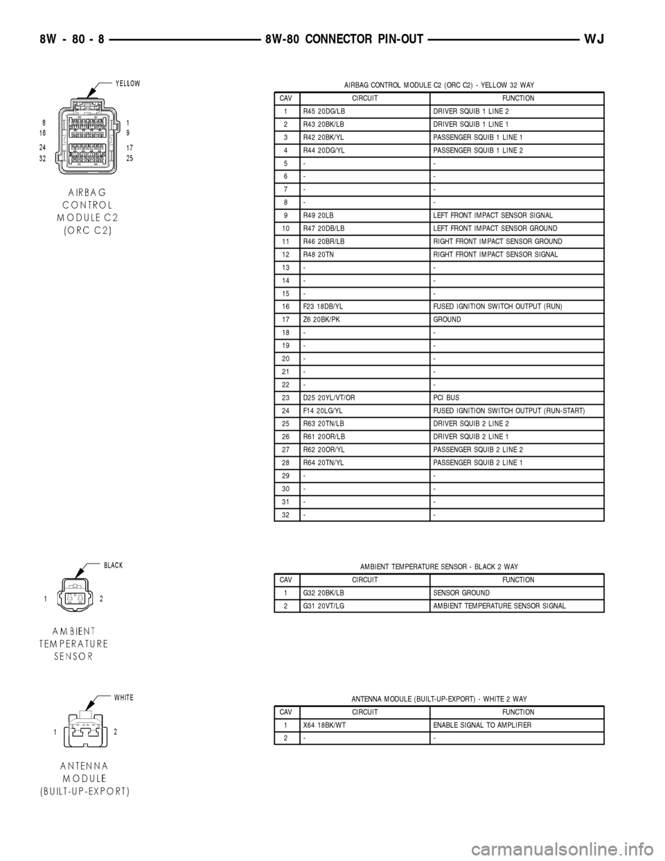
AIRBAG CONTROL MODULE C2 (ORC C2) - YELLOW 32 WAY
CAV CIRCUIT FUNCTION
1 R45 20DG/LB DRIVER SQUIB 1 LINE 2
2 R43 20BK/LB DRIVER SQUIB 1 LINE 1
3 R42 20BK/YL PASSENGER SQUIB 1 LINE 1
4 R44 20DG/YL PASSENGER SQUIB 1 LINE 2
5- -
6- -
7- -
8- -
9 R49 20LB LEFT FRONT IMPACT SENSOR SIGNAL
10 R47 20DB/LB LEFT FRONT IMPACT SENSOR GROUND
11 R46 20BR/LB RIGHT FRONT IMPACT SENSOR GROUND
12 R48 20TN RIGHT FRONT IMPACT SENSOR SIGNAL
13 - -
14 - -
15 - -
16 F23 18DB/YL FUSED IGNITION SWITCH OUTPUT (RUN)
17 Z6 20BK/PK GROUND
18 - -
19 - -
20 - -
21 - -
22 - -
23 D25 20YL/VT/OR PCI BUS
24 F14 20LG/YL FUSED IGNITION SWITCH OUTPUT (RUN-START)
25 R63 20TN/LB DRIVER SQUIB 2 LINE 2
26 R61 20OR/LB DRIVER SQUIB 2 LINE 1
27 R62 20OR/YL PASSENGER SQUIB 2 LINE 2
28 R64 20TN/YL PASSENGER SQUIB 2 LINE 1
29 - -
30 - -
31 - -
32 - -
AMBIENT TEMPERATURE SENSOR - BLACK 2 WAY
CAV CIRCUIT FUNCTION
1 G32 20BK/LB SENSOR GROUND
2 G31 20VT/LG AMBIENT TEMPERATURE SENSOR SIGNAL
ANTENNA MODULE (BUILT-UP-EXPORT) - WHITE 2 WAY
CAV CIRCUIT FUNCTION
1 X64 18BK/WT ENABLE SIGNAL TO AMPLIFIER
2- -
8W - 80 - 8 8W-80 CONNECTOR PIN-OUTWJ
Page 1160 of 2199

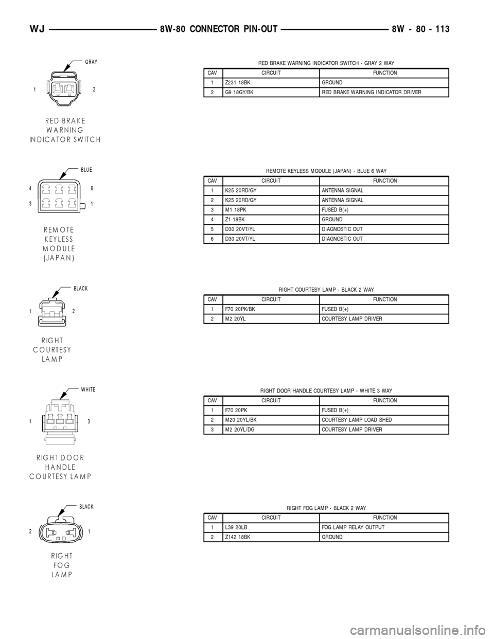
RED BRAKE WARNING INDICATOR SWITCH - GRAY 2 WAY
CAV CIRCUIT FUNCTION
1 Z231 18BK GROUND
2 G9 18GY/BK RED BRAKE WARNING INDICATOR DRIVER
REMOTE KEYLESS MODULE (JAPAN) - BLUE 6 WAY
CAV CIRCUIT FUNCTION
1 K25 20RD/GY ANTENNA SIGNAL
2 K25 20RD/GY ANTENNA SIGNAL
3 M1 18PK FUSED B(+)
4 Z1 18BK GROUND
5 D30 20VT/YL DIAGNOSTIC OUT
6 D30 20VT/YL DIAGNOSTIC OUT
RIGHT COURTESY LAMP - BLACK 2 WAY
CAV CIRCUIT FUNCTION
1 F70 20PK/BK FUSED B(+)
2 M2 20YL COURTESY LAMP DRIVER
RIGHT DOOR HANDLE COURTESY LAMP - WHITE 3 WAY
CAV CIRCUIT FUNCTION
1 F70 20PK FUSED B(+)
2 M20 20YL/BK COURTESY LAMP LOAD SHED
3 M2 20YL/DG COURTESY LAMP DRIVER
RIGHT FOG LAMP - BLACK 2 WAY
CAV CIRCUIT FUNCTION
1 L39 20LB FOG LAMP RELAY OUTPUT
2 Z142 18BK GROUND
WJ8W-80 CONNECTOR PIN-OUT 8W - 80 - 113
Page 1176 of 2199

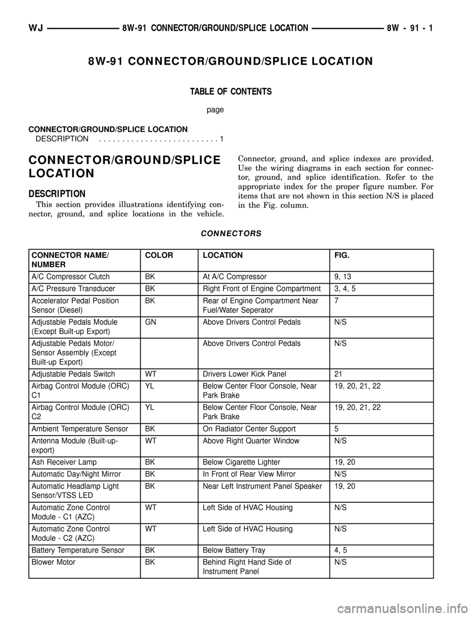
8W-91 CONNECTOR/GROUND/SPLICE LOCATION
TABLE OF CONTENTS
page
CONNECTOR/GROUND/SPLICE LOCATION
DESCRIPTION..........................1
CONNECTOR/GROUND/SPLICE
LOCATION
DESCRIPTION
This section provides illustrations identifying con-
nector, ground, and splice locations in the vehicle.Connector, ground, and splice indexes are provided.
Use the wiring diagrams in each section for connec-
tor, ground, and splice identification. Refer to the
appropriate index for the proper figure number. For
items that are not shown in this section N/S is placed
in the Fig. column.
CONNECTORS
CONNECTOR NAME/
NUMBERCOLOR LOCATION FIG.
A/C Compressor Clutch BK At A/C Compressor 9, 13
A/C Pressure Transducer BK Right Front of Engine Compartment 3, 4, 5
Accelerator Pedal Position
Sensor (Diesel)BK Rear of Engine Compartment Near
Fuel/Water Seperator7
Adjustable Pedals Module
(Except Built-up Export)GN Above Drivers Control Pedals N/S
Adjustable Pedals Motor/
Sensor Assembly (Except
Built-up Export)Above Drivers Control Pedals N/S
Adjustable Pedals Switch WT Drivers Lower Kick Panel 21
Airbag Control Module (ORC)
C1YL Below Center Floor Console, Near
Park Brake19, 20, 21, 22
Airbag Control Module (ORC)
C2YL Below Center Floor Console, Near
Park Brake19, 20, 21, 22
Ambient Temperature Sensor BK On Radiator Center Support 5
Antenna Module (Built-up-
export)WT Above Right Quarter Window N/S
Ash Receiver Lamp BK Below Cigarette Lighter 19, 20
Automatic Day/Night Mirror BK In Front of Rear View Mirror N/S
Automatic Headlamp Light
Sensor/VTSS LEDBK Near Left Instrument Panel Speaker 19, 20
Automatic Zone Control
Module - C1 (AZC)WT Left Side of HVAC Housing N/S
Automatic Zone Control
Module - C2 (AZC)WT Left Side of HVAC Housing N/S
Battery Temperature Sensor BK Below Battery Tray 4, 5
Blower Motor BK Behind Right Hand Side of
Instrument PanelN/S
WJ8W-91 CONNECTOR/GROUND/SPLICE LOCATION 8W - 91 - 1
Page 1902 of 2199

(8) Loosen screw under hood hinge, attaching
fender to engine compartment rail.
(9) Remove screws attaching fender to engine com-
partment rail (Fig. 7).
(10) Right fender only:
(a) If equipped, remove radio antenna.
(11) Separate fender from body.
INSTALLATION
(1) Position fender on body.
(2) Right fender only:
(a) If equipped, install radio antenna.
(3) Install all screws finger-tight.
(4) Align fender with adjacent body panels and
wax crayon reference marks.
(5) Tighten all screws.
(6) Install inner fender liner.
FUEL FILL DOOR
REMOVAL
(1) Open the fuel filler door.
(2) Remove the screws attaching the door to the
quarter panel (Fig. 8).
(3) Remove the door from the panel.
INSTALLATION
(1) Position the fuel filler door on the quarter
panel with the screw holes aligned.(2) Install the screws attaching the fuel filler door
to the quarter panel.
GRILLE
REMOVAL
(1) Remove fascia, refer to (Refer to 13 - FRAMES
& BUMPERS/BUMPERS/FRONT FASCIA - REMOV-
AL).
(2) Disengage retainers attaching grille insert to
grille/fascia.
(3) Separate grille insert from grille/fascia (Fig. 9).
INSTALLATION
(1) Position grille insert in grille/fascia (Fig. 9).
(2) Engage retainers attaching grille insert to
grille/fascia.
Fig. 7 Upper Fender Mounting
1 - FENDER
2 - BODY
Fig. 8 Fuel Filler Door
1 - FUEL FILL DOOR
Fig. 9 Grille Insert
1 - GRILLE/FASCIA
2 - INSERT
WJEXTERIOR 23 - 29
FRONT FENDER (Continued)
Page 1914 of 2199

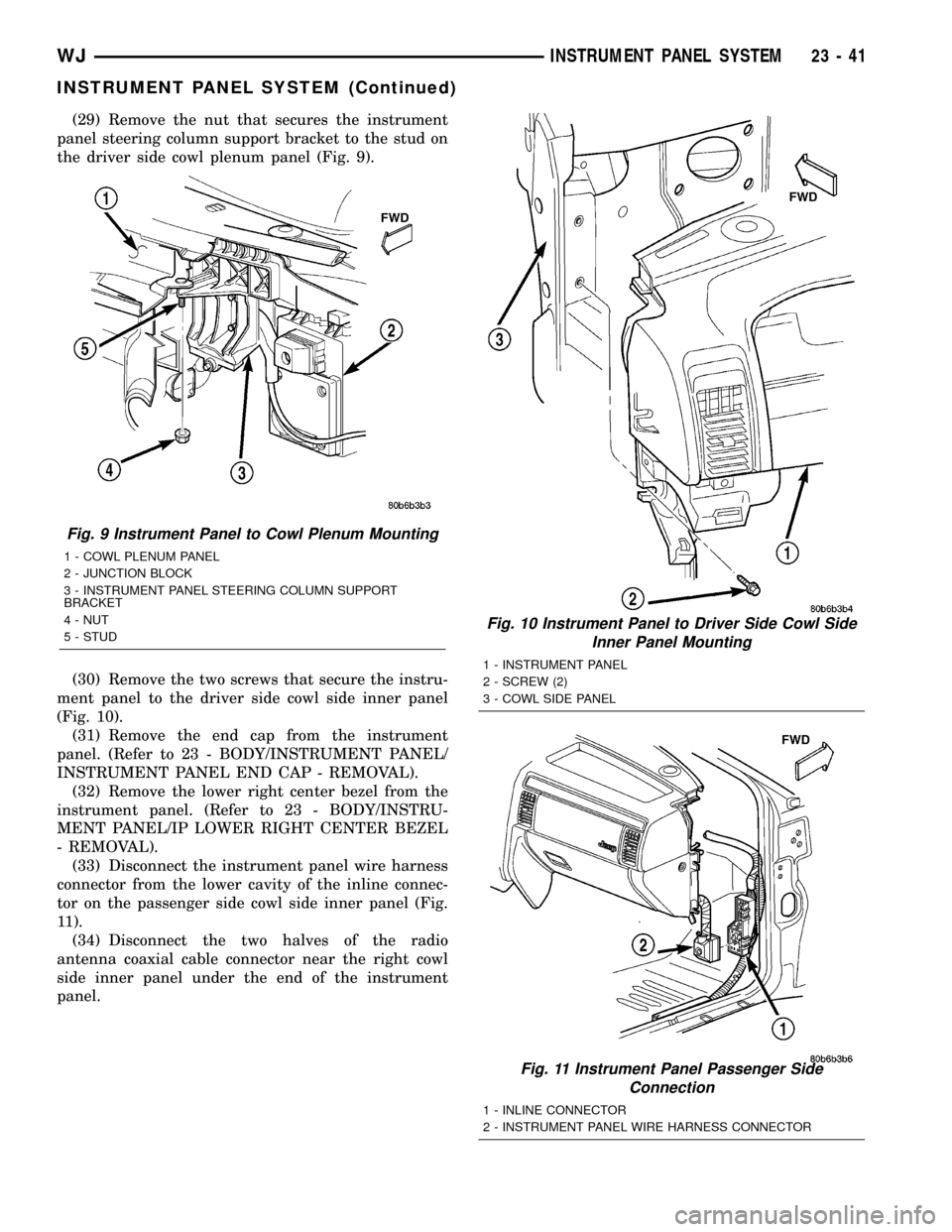
(29) Remove the nut that secures the instrument
panel steering column support bracket to the stud on
the driver side cowl plenum panel (Fig. 9).
(30) Remove the two screws that secure the instru-
ment panel to the driver side cowl side inner panel
(Fig. 10).
(31) Remove the end cap from the instrument
panel. (Refer to 23 - BODY/INSTRUMENT PANEL/
INSTRUMENT PANEL END CAP - REMOVAL).
(32) Remove the lower right center bezel from the
instrument panel. (Refer to 23 - BODY/INSTRU-
MENT PANEL/IP LOWER RIGHT CENTER BEZEL
- REMOVAL).
(33) Disconnect the instrument panel wire harness
connector from the lower cavity of the inline connec-
tor on the passenger side cowl side inner panel (Fig.
11).
(34) Disconnect the two halves of the radio
antenna coaxial cable connector near the right cowl
side inner panel under the end of the instrument
panel.
Fig. 9 Instrument Panel to Cowl Plenum Mounting
1 - COWL PLENUM PANEL
2 - JUNCTION BLOCK
3 - INSTRUMENT PANEL STEERING COLUMN SUPPORT
BRACKET
4 - NUT
5 - STUD
Fig. 10 Instrument Panel to Driver Side Cowl Side
Inner Panel Mounting
1 - INSTRUMENT PANEL
2 - SCREW (2)
3 - COWL SIDE PANEL
Fig. 11 Instrument Panel Passenger Side
Connection
1 - INLINE CONNECTOR
2 - INSTRUMENT PANEL WIRE HARNESS CONNECTOR
WJINSTRUMENT PANEL SYSTEM 23 - 41
INSTRUMENT PANEL SYSTEM (Continued)
Page 1916 of 2199

INSTALLATION
WARNING: ON VEHICLES EQUIPPED WITH AIR-
BAGS, DISABLE THE AIRBAG SYSTEM BEFORE
ATTEMPTING ANY STEERING WHEEL, STEERING
COLUMN, OR INSTRUMENT PANEL COMPONENT
DIAGNOSIS OR SERVICE. DISCONNECT AND ISO-
LATE THE BATTERY NEGATIVE (GROUND) CABLE,
THEN WAIT TWO MINUTES FOR THE AIRBAG SYS-
TEM CAPACITOR TO DISCHARGE BEFORE PER-
FORMING FURTHER DIAGNOSIS OR SERVICE. THIS
IS THE ONLY SURE WAY TO DISABLE THE AIRBAG
SYSTEM. FAILURE TO TAKE THE PROPER PRE-
CAUTIONS COULD RESULT IN ACCIDENTAL AIR-
BAG DEPLOYMENT AND POSSIBLE PERSONAL
INJURY.
(1) Prior to installing the instrument panel into
the vehicle, loosen the three nuts that secure the
instrument panel intermediate bracket and the accel-
erator pedal assembly to the studs on the dash panel
(Fig. 8).
(2) With the aid of an assistant, load the instru-
ment panel assembly through the driver side front
door of the vehicle and hang it on the studs on the
dash panel near the windshield fence line (Fig. 1).
(3) Be certain that the molded plastic hook forma-
tions on the instrument panel structural duct are
inserted into and seated in the guide holes at each
cowl side inner panel.
(4) Loosely install the two screws that secure each
end of the instrument panel to the cowl side inner
panels.
(5) Install and tighten the two screws that secure
the passenger side instrument panel structural duct
to the heater and air conditioner housing (Fig. 13).
Tighten the screws to 11.8 N´m (105 in. lbs.).
(6) Install and tighten the one screw that secures
the instrument panel steering column support
bracket to the driver side end of the heater and air
conditioner housing (Fig. 7). Tighten the screw to
11.8 N´m (105 in. lbs.).
(7) Tighten the two screws that secure each end of
the instrument panel to the cowl side inner panels
(Fig. 10) and (Fig. 14). Tighten the screws to 11.8
N´m (105 in. lbs.).
(8) Install and tighten the one screw that secures
the instrument panel steering column support
bracket to the intermediate bracket on the driver
side dash panel (Fig. 8). Tighten the screw to 11.3
N´m (100 in. lbs.).
(9) Tighten the three nuts that secure the instru-
ment panel intermediate bracket and the accelerator
pedal assembly to the studs on the dash panel.
Tighten the nuts to 11.3 N´m (100 in. lbs.).(10) Install and tighten the four nuts that secure
the instrument panel to the studs on the dash panel
near the windshield fence line. Tighten the nuts to
11.8 N´m (105 in. lbs.).
(11) Install and tighten the nut that secures the
instrument panel steering column support bracket to
the stud on the driver side cowl plenum panel (Fig.
9). Tighten the nut to 28.2 N´m (250 in. lbs.).
(12) Reinstall the instrument panel to center floor
tunnel bracket onto the instrument panel and the
floor panel transmission tunnel. (Refer to 23 - BODY/
INSTRUMENT PANEL/IP CENTER FLOOR TUN-
NEL BRACKET - INSTALLATION).
(13) Reconnect the two instrument panel wire har-
ness connectors to the two heater and air conditioner
housing connectors located near the blower motor on
the passenger side end of the housing (Fig. 12).
(14) Reconnect the two halves of the radio antenna
coaxial cable connector near the right cowl side inner
panel under the end of the instrument panel.
(15) Reconnect the instrument panel wire harness
connector to the lower cavity of the inline connector
on the passenger side cowl side inner panel and
tighten the connector screw (Fig. 11). Tighten the
screw to 4 N´m (36 in. lbs.).
(16) Reinstall the lower right center bezel onto the
instrument panel. (Refer to 23 - BODY/INSTRU-
MENT PANEL/IP LOWER RIGHT CENTER BEZEL
- INSTALLATION).
(17) Reinstall the end cap onto the instrument
panel. (Refer to 23 - BODY/INSTRUMENT PANEL/
INSTRUMENT PANEL END CAP - INSTALLA-
TION).
(18) If the vehicle is equipped with the manual
heating and air conditioning system, reconnect the
vacuum harness connector located near the driver
side of the floor panel transmission tunnel behind
the driver side floor duct.
(19) Position the driver side floor duct to the
heater and air conditioner housing near the driver
side of the floor panel transmission tunnel (Fig. 7).
(20) Install and tighten the one screw that secures
the driver side floor duct to the heater and air con-
ditioner housing near the driver side of the floor
panel transmission tunnel. Tighten the screw to 2.2
N´m (20 in. lbs.).
(21) Route the instrument panel wire harness to
the floor panel transmission tunnel and engage the
retainers that secure the harness to the mounting
brackets on the tunnel (Fig. 6).
(22) Install the instrument panel wire harness
ground eyelets to the studs on the floor panel trans-
mission tunnel in front of and behind the airbag con-
trol module and secure the eyelets with nuts. Tighten
the nuts to 7.3 N´m (65 in. lbs.).
WJINSTRUMENT PANEL SYSTEM 23 - 43
INSTRUMENT PANEL SYSTEM (Continued)