Cable JEEP GRAND CHEROKEE 2002 WJ / 2.G Owner's Manual
[x] Cancel search | Manufacturer: JEEP, Model Year: 2002, Model line: GRAND CHEROKEE, Model: JEEP GRAND CHEROKEE 2002 WJ / 2.GPages: 2199, PDF Size: 76.01 MB
Page 213 of 2199

(3) Push the cables into the upper suspension arm
brackets.
(4) Install the cable retainer bolts to the rear
spring pads.
(5) Install the ABS sensor wiring harness to the
rear brake cables.
(6) Install the rotors, caliper anchors and brake
calipers.
(7) Install the wheel and tire assemblies.
(8) Remove support and lower the vehicle.
(9) Engage the cable ends into the parking brake
equalizer.
(10) Pull on the lever to release the lock out
spring.
(11) Install center console, (Refer to 23 - BODY/IN-
TERIOR/FLOOR CONSOLE - INSTALLATION).
(12) Fold down the rear carpet cover and rear seat.
(13) Verify parking brake operation.
LEVER
REMOVAL
(1) Remove center console,(Refer to 23 - BODY/IN-
TERIOR/FLOOR CONSOLE - REMOVAL).
(2) Lift up rear seat and carpet covering the park-
ing brake cables.
(3) Place a screw driver through the front cable
eyelet (Fig. 77) and pry back on the front cable.(4) Have an assistant pry down the lock out spring
through the hole in the side of the park brake lever
(Fig. 78) with a small screw driver. Then slowly
release the front cable.
NOTE: Their should be slack in the cable if the lock
out spring is engaged.
(5) Disconnect parking brake switch wiring con-
nector.
(6) Disengage front cable end from parking brake
lever.
(7) Compress the cable retainer with a 13 mm
wrench (Fig. 79) and remove the cable from the park-
ing brake lever bracket.
Fig. 77 FRONT CABLE
1 - REAR CABLES
2 - FRONT CABLE EYELET
3 - FRONT CABLE
4 - EQUALIZER
Fig. 78 Lock Out Spring
1 - LOCK OUT SPRING
Fig. 79 Parking Brake Lever Bracket
1 - FRONT CABLE
2 - WRENCH
5 - 38 BRAKES - BASEWJ
CABLES (Continued)
Page 214 of 2199

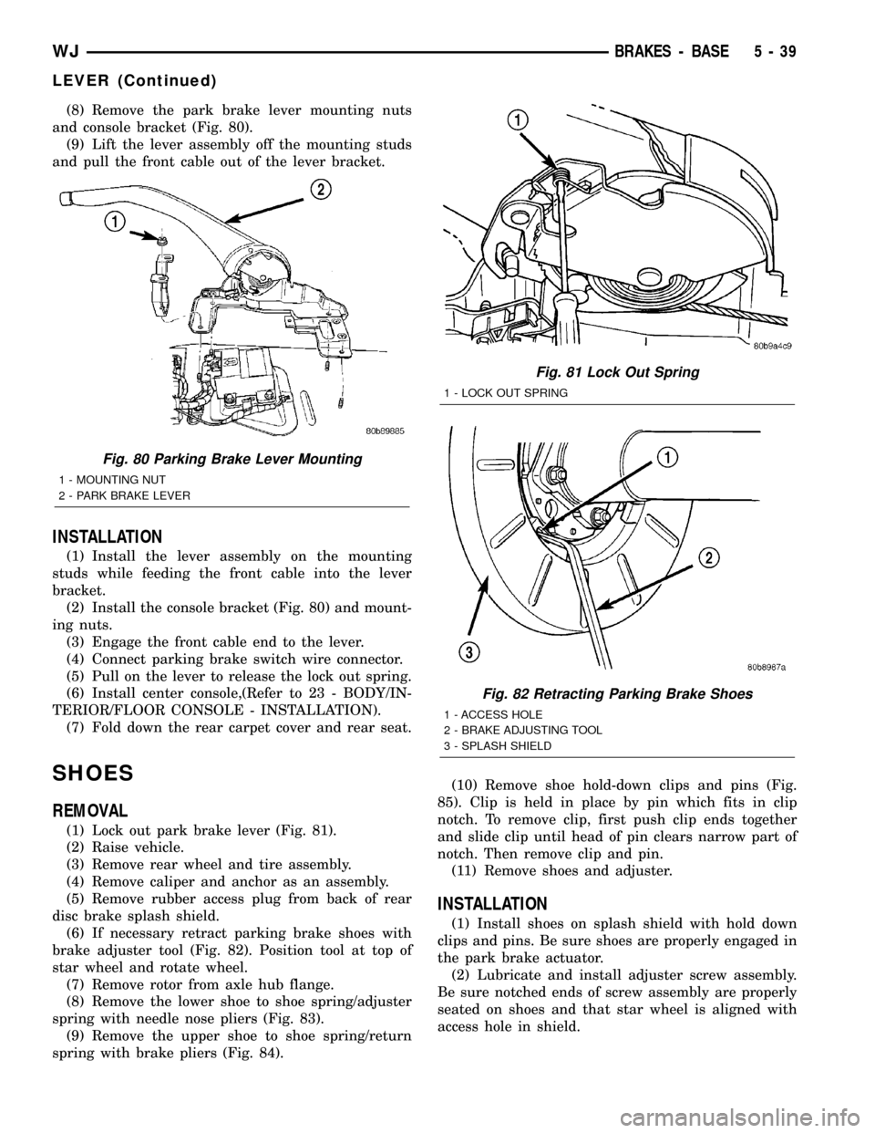
(8) Remove the park brake lever mounting nuts
and console bracket (Fig. 80).
(9) Lift the lever assembly off the mounting studs
and pull the front cable out of the lever bracket.
INSTALLATION
(1) Install the lever assembly on the mounting
studs while feeding the front cable into the lever
bracket.
(2) Install the console bracket (Fig. 80) and mount-
ing nuts.
(3) Engage the front cable end to the lever.
(4) Connect parking brake switch wire connector.
(5) Pull on the lever to release the lock out spring.
(6) Install center console,(Refer to 23 - BODY/IN-
TERIOR/FLOOR CONSOLE - INSTALLATION).
(7) Fold down the rear carpet cover and rear seat.
SHOES
REMOVAL
(1) Lock out park brake lever (Fig. 81).
(2) Raise vehicle.
(3) Remove rear wheel and tire assembly.
(4) Remove caliper and anchor as an assembly.
(5) Remove rubber access plug from back of rear
disc brake splash shield.
(6) If necessary retract parking brake shoes with
brake adjuster tool (Fig. 82). Position tool at top of
star wheel and rotate wheel.
(7) Remove rotor from axle hub flange.
(8) Remove the lower shoe to shoe spring/adjuster
spring with needle nose pliers (Fig. 83).
(9) Remove the upper shoe to shoe spring/return
spring with brake pliers (Fig. 84).(10) Remove shoe hold-down clips and pins (Fig.
85). Clip is held in place by pin which fits in clip
notch. To remove clip, first push clip ends together
and slide clip until head of pin clears narrow part of
notch. Then remove clip and pin.
(11) Remove shoes and adjuster.
INSTALLATION
(1) Install shoes on splash shield with hold down
clips and pins. Be sure shoes are properly engaged in
the park brake actuator.
(2) Lubricate and install adjuster screw assembly.
Be sure notched ends of screw assembly are properly
seated on shoes and that star wheel is aligned with
access hole in shield.
Fig. 80 Parking Brake Lever Mounting
1 - MOUNTING NUT
2 - PARK BRAKE LEVER
Fig. 81 Lock Out Spring
1 - LOCK OUT SPRING
Fig. 82 Retracting Parking Brake Shoes
1 - ACCESS HOLE
2 - BRAKE ADJUSTING TOOL
3 - SPLASH SHIELD
WJBRAKES - BASE 5 - 39
LEVER (Continued)
Page 220 of 2199

(3) Connect the harness to the switch. Be sure the
harness connector is firmly seated.
(4) Place the carpet in position and fold the rear
seat back down.
REAR WHEEL SPEED SENSOR
DESCRIPTION
A wheel speed sensor is used at each wheel. The
front sensors are mounted to the steering knuckles.The rear sensors are mounted at the outboard end of
the axle. Tone wheels are mounted to the outboard
ends of the front and rear axle shafts. The gear type
tone wheel serves as the trigger mechanism for each
sensor.
OPERATION
The sensors convert wheel speed into a small digi-
tal signal. The CAB sends 12 volts to the sensors.
The sensor has an internal magneto resistance
bridge that alters the voltage and amperage of the
signal circuit. This voltage and amperage is changed
by magnetic induction when the toothed tone wheel
passes the wheel speed sensor. This digital signal is
sent to the CAB. The CAB measures the voltage and
amperage of the digital signal for each wheel.
REMOVAL
(1) Raise and fold the rear seat forward. Then
move the carpeting aside for access to the rear sensor
connectors.
(2) Disconnect the rear sensor wire at the harness
connectors (Fig. 7).
(3) Push the sensor wires and grommets through
the floorpan holes.
(4) Raise and support the vehicle.
(5) Disengage the sensor wire from the axle and
the chassis brackets and from the brake line retain-
ers.
(6) Remove the sensor mounting bolt from the rear
brake backing plate. (Fig. 8).
(7) Remove the sensor from the backing plate.
Fig. 5 G-Switch Mounting
1 - MOUNTING BOLTS
2 - CONNECTOR
3 - G-SWITCH
Fig. 6 G-Switch
1 - SWITCH PART NUMBER
2 - ARROW INDICATES FRONT OF SWITCH FOR PROPER
MOUNTING
Fig. 7 Rear Sensor Connector
1 - RIGHT REAR WHEEL SPEED SENSOR CONNECTOR
2 - LEFT REAR WHEEL SPEED SENSOR CONNECTOR
3 - G-SWITCH SENSOR
4 - PARKING BRAKE CABLES
WJBRAKES - ABS 5 - 45
G-SWITCH (Continued)
Page 222 of 2199

PRESSURE HOLD
Both solenoid valves are closed in the pressure
hold cycle. Fluid apply pressure in the control chan-
nel is maintained at a constant rate. The CAB main-
tains the hold cycle until sensor inputs indicate a
pressure change is necessary.
PRESSURE INCREASE
The inlet valve is open and the outlet valve is
closed during the pressure increase cycle. The pres-
sure increase cycle is used to counteract unequal
wheel speeds. This cycle controls re-application of
fluid apply pressure due to changing road surfaces or
wheel speed.
REMOVAL
(1) Remove the negative battery cable from the
battery.
(2) Remove the air cleaner housing,(Refer to 9 -
ENGINE/AIR INTAKE SYSTEM/AIR CLEANER
HOUSING - REMOVAL).
(3) Pull the CAB harness connector release up and
remove connector (Fig. 10).(4) Remove the brake lines from the HCU.
(5) Remove the HCU/CAB side mounting bolt and
the two rear mounting bolts. (Fig. 11).
(6) Remove the HCU/CAB assembly from the vehi-
cle.
INSTALLATION
(1) Install HCU/CAB assembly into the mounting
bracket and tighten mounting bolts to 12 N´m (9 ft.
lbs.).
(2) Install the brake lines to the HCU and tighten
to 16 N´m (12 ft. lbs.).
(3) Install CAB harness connector and push down
connector release.
(4) Install air cleaner housing,(Refer to 9 -
ENGINE/AIR INTAKE SYSTEM/AIR CLEANER
HOUSING - INSTALLATION).
(5) Install negative battery cable to the battery.
(6) Bleed base and ABS brake systems,(Refer to 5 -
BRAKES - STANDARD PROCEDURE) OR (Refer to
5 - BRAKES - STANDARD PROCEDURE).
Fig. 10 CAB Connector Release
1 - CONNECTOR RELEASE
2 - CAB
Fig. 11 HCU/CAB Assembly
1 - SIDE MOUNTING BOLT
2 - REAR MOUNTING BOLTS
WJBRAKES - ABS 5 - 47
HCU (HYDRAULIC CONTROL UNIT) (Continued)
Page 234 of 2199

Carefully remove radiator pressure cap from filler
neck and check coolant level. Push down on cap to
disengage it from stop tabs. Wipe inside of filler neck
and examine lower inside sealing seat for nicks,
cracks, paint, dirt and solder residue. Inspect radia-
tor-to- reserve/overflow tank hose for internal
obstructions. Insert a wire through the hose to be
sure it is not obstructed.
Inspect cams on outside of filler neck. If cams are
damaged, seating of pressure cap valve and tester
seal will be affected.
Attach pressure tester (7700 or an equivalent) to
radiator filler neck (Fig. 6).
Operate tester pump to apply 103.4 kPa (15 psi)
pressure to system. If hoses enlarge excessively or
bulges while testing, replace as necessary. Observe
gauge pointer and determine condition of cooling sys-
tem according to following criteria:
Holds Steady:If pointer remains steady for two
minutes, serious coolant leaks are not present in sys-
tem. However, there could be an internal leak that
does not appear with normal system test pressure. If
it is certain that coolant is being lost and leaks can-
not be detected, inspect for interior leakage or per-
form Internal Leakage Test.
Drops Slowly:Indicates a small leak or seepage
is occurring. Examine all connections for seepage or
slight leakage with a flashlight. Inspect radiator,
hoses, gasket edges and heater. Seal small leak holes
with a Sealer Lubricant (or equivalent). Repair leak
holes and inspect system again with pressure
applied.
Drops Quickly:Indicates that serious leakage is
occurring. Examine system for external leakage. If
leaks are not visible, inspect for internal leakage.
Large radiator leak holes should be repaired by a
reputable radiator repair shop.INTERNAL LEAKAGE INSPECTION
Remove engine oil pan drain plug and drain a
small amount of engine oil. If coolant is present in
the pan, it will drain first because it is heavier than
oil. An alternative method is to operate engine for a
short period to churn the oil. After this is done,
remove engine dipstick and inspect for water glob-
ules. Also inspect transmission dipstick for water
globules and transmission fluid cooler for leakage.
WARNING: WITH RADIATOR PRESSURE TESTER
TOOL INSTALLED ON RADIATOR, DO NOT ALLOW
PRESSURE TO EXCEED 110 KPA (20 PSI). PRES-
SURE WILL BUILD UP QUICKLY IF A COMBUSTION
LEAK IS PRESENT. TO RELEASE PRESSURE,
ROCK TESTER FROM SIDE TO SIDE. WHEN
REMOVING TESTER, DO NOT TURN TESTER MORE
THAN 1/2 TURN IF SYSTEM IS UNDER PRESSURE.
Operate engine without pressure cap on radiator
until thermostat opens. Attach a Pressure Tester to
filler neck. If pressure builds up quickly it indicates a
combustion leak exists. This is usually the result of a
cylinder head gasket leak or crack in engine. Repair
as necessary.
If there is not an immediate pressure increase,
pump the Pressure Tester. Do this until indicated
pressure is within system range of 110 kPa (16 psi).
Fluctuation of gauge pointer indicates compression or
combustion leakage into cooling system.
Because the vehicle is equipped with a catalytic
converter,do notremove spark plug cables or short
out cylinders to isolate compression leak.
If the needle on dial of pressure tester does not
fluctuate, race engine a few times to check for an
abnormal amount of coolant or steam. This would be
emitting from exhaust pipe. Coolant or steam from
exhaust pipe may indicate a faulty cylinder head gas-
ket, cracked engine cylinder block or cylinder head.
A convenient check for exhaust gas leakage into
cooling system is provided by a commercially avail-
able Block Leak Check tool. Follow manufacturers
instructions when using this product.
COMBUSTION LEAKAGE TEST - WITHOUT
PRESSURE TESTER
DO NOT WASTE reusable coolant. If solution is
clean, drain coolant into a clean container for reuse.
WARNING: DO NOT REMOVE CYLINDER BLOCK
DRAIN PLUGS OR LOOSEN RADIATOR DRAIN-
COCK WITH SYSTEM HOT AND UNDER PRESSURE.
SERIOUS BURNS FROM COOLANT CAN OCCUR.
Drain sufficient coolant to allow thermostat
removal. (Refer to 7 - COOLING/ENGINE/ENGINE
COOLANT THERMOSTAT - REMOVAL). Remove
Fig. 6 Pressure Testing Cooling SystemÐTypical
1 - TYPICAL COOLING SYSTEM PRESSURE TESTER
WJCOOLING 7 - 11
COOLING (Continued)
Page 242 of 2199

CONDITION POSSIBLE CAUSES CORRECTION
BELT BROKEN (NOTE: IDENTIFY
AND CORRECT PROBLEM
BEFORE NEW BELT IS
INSTALLED)1. Excessive tension. 1. Replace belt and automatic belt
tensioner.
2. Incorrect belt. 2. Replace belt.
3. Tensile member damaged during
belt installation.3. Replace belt.
4. Severe misalignment. 4. Check and replace.
5. Bracket, pulley, or bearing failure. 5. Replace defective component
and belt.
NOISE (OBJECTIONABLE
SQUEAL, SQUEAK, OR RUMBLE
IS HEARD OR FELT WHILE
DRIVE BELT IS IN OPERATION)1. Belt slippage. 1. Replace belt or automatic belt
tensioner.
2. Bearing noise. 2. Locate and repair.
3. Belt misalignment. 3. Replace belt.
4. Belt-to-pulley mismatch. 4. Install correct belt.
REMOVALÐ4.0L ENGINE
NOTE: The belt routing schematics are published
from the latest information available at the time of
publication. If anything differs between these sche-
matics and the Belt Routing Label, use the sche-
matics on Belt Routing Label. This label is located
in the engine compartment.
CAUTION: DO NOT LET TENSIONER ARM SNAP
BACK TO THE FREEARM POSITION, SEVERE DAM-
AGE MAY OCCUR TO THE TENSIONER.
Belt tension is not adjustable. Belt adjustment is
maintained by an automatic ( spring load ) belt ten-
sioner.
(1) Disconnect negative battery cable from battery.
(2) Rotate belt tensioner until it contacts its stop.
Remove belt, then slowly rotate the tensioner into
the freearm position. (Fig. 4).
INSTALLATIONÐ4.0L ENGINE
NOTE: The belt routing schematics are published
from the latest information available at the time of
publication. If anything differs between these sche-
matics and the Belt Routing Label, use the sche-
matics on Belt Routing Label. This label is located
in the engine compartment.
Belt tension is not adjustable. Belt adjustment is
maintained by an automatic ( spring load ) belt ten-
sioner.
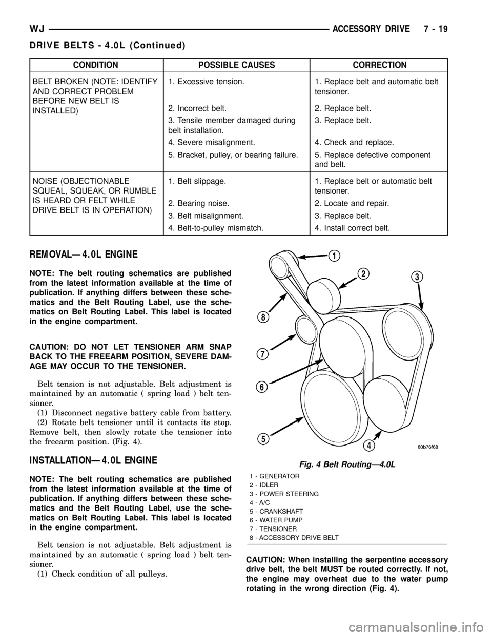
(1) Check condition of all pulleys.CAUTION: When installing the serpentine accessory
drive belt, the belt MUST be routed correctly. If not,
the engine may overheat due to the water pump
rotating in the wrong direction (Fig. 4).
Fig. 4 Belt RoutingÐ4.0L
1 - GENERATOR
2 - IDLER
3 - POWER STEERING
4 - A/C
5 - CRANKSHAFT
6 - WATER PUMP
7 - TENSIONER
8 - ACCESSORY DRIVE BELT
WJACCESSORY DRIVE 7 - 19
DRIVE BELTS - 4.0L (Continued)
Page 245 of 2199

CONDITION POSSIBLE CAUSES CORRECTION
BELT BROKEN (NOTE: IDENTIFY
AND CORRECT PROBLEM
BEFORE NEW BELT IS
INSTALLED)1. Excessive tension. 1. Replace belt and automatic belt
tensioner.
2. Incorrect belt. 2. Replace belt.
3. Tensile member damaged during
belt installation.3. Replace belt.
4. Severe misalignment. 4. Check and replace.
5. Bracket, pulley, or bearing failure. 5. Replace defective component
and belt.
NOISE (OBJECTIONABLE
SQUEAL, SQUEAK, OR RUMBLE
IS HEARD OR FELT WHILE
DRIVE BELT IS IN OPERATION)1. Belt slippage. 1. Replace belt or automatic belt
tensioner.
2. Bearing noise. 2. Locate and repair.
3. Belt misalignment. 3. Replace belt.
4. Belt-to-pulley mismatch. 4. Install correct belt.
REMOVAL - 4.7L ENGINE
NOTE: The belt routing schematics are published
from the latest information available at the time of
publication. If anything differs between these sche-
matics and the Belt Routing Label, use the sche-
matics on Belt Routing Label. This label is located
in the engine compartment.
CAUTION: DO NOT LET TENSIONER ARM SNAP
BACK TO THE FREEARM POSITION, SEVERE DAM-
AGE MAY OCCUR TO THE TENSIONER.
Belt tension is not adjustable. Belt adjustment is
maintained by an automatic ( spring load ) belt ten-
sioner.
(1) Disconnect negative battery cable from battery.
(2) Rotate belt tensioner until it contacts its stop.
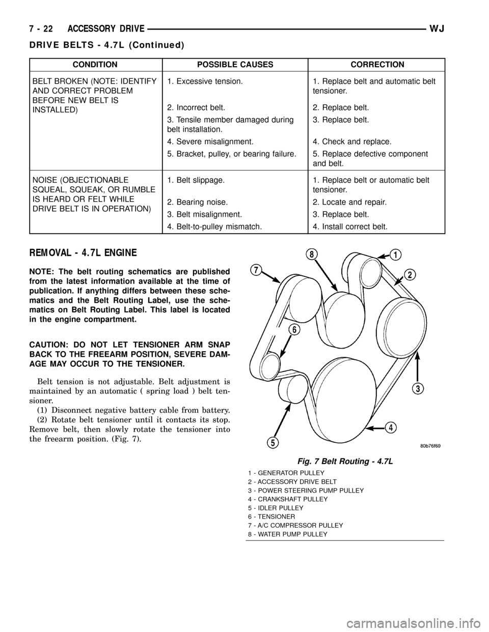
Remove belt, then slowly rotate the tensioner into
the freearm position. (Fig. 7).
Fig. 7 Belt Routing - 4.7L
1 - GENERATOR PULLEY
2 - ACCESSORY DRIVE BELT
3 - POWER STEERING PUMP PULLEY
4 - CRANKSHAFT PULLEY
5 - IDLER PULLEY
6 - TENSIONER
7 - A/C COMPRESSOR PULLEY
8 - WATER PUMP PULLEY
7 - 22 ACCESSORY DRIVEWJ
DRIVE BELTS - 4.7L (Continued)
Page 254 of 2199

NOTE: When ever the high pressure line fittings are
removed from the hydraulic fan drive the o-rings
located on the fittings must be replaced.
(7) Lubricate the o-rings on the fittings with power
steering fluid then connect inlet and outlet high pres-
sure lines to fan drive (Fig. 9). Tighten inlet line to
49 N´m (36 ft. lbs.) tighten outlet line to 29 N´m (21.5
ft. lbs.).
(8) Connect low pressure return hose to fan drive
(Fig. 9).
(9) Lower vehicle.
(10) Install radiator upper hose.
(11) Connect electrical connector for hydraulic fan
control solenoid.
(12) Tighten fan shroud upper mounting bolts to 6
N´m (50 in. lbs.).
(13) Refill cooling system (Refer to 7 - COOLING -
STANDARD PROCEDURE).
CAUTION: Do not run engine with power steering
fluid below the full mark in the reservoir. Sever
damage to the hydraulic cooling fan or the engine
can occur.(14) Refill power steering fluid reservoir and bleed
air from steering system (Refer to 19 - STEERING/
PUMP - STANDARD PROCEDURE).
(15) Run engine and check for leaks.
RADIATOR FAN - 4.0L
DESCRIPTION
The radiator cooling fan used on the 4.0L engine is
an hybrid fan design. The hybrid fan system consist
of a low speed viscous driven mechanical fan and a
electrical fan (Fig. 10).
REMOVAL
(1) Disconnect negative battery cable from battery.
(2) The thermal viscous fan drive/fan blade assem-
bly is attached (threaded) to water pump hub shaft.
Remove fan blade/viscous fan drive assembly from
water pump by turning mounting nut counterclock-
wise as viewed from front (Fig. 11). Threads on vis-
cous fan drive areRIGHT HAND.
(3) Do not attempt to remove fan/viscous fan drive
assembly from vehicle at this time.
(4) Do not unbolt fan blade assembly from viscous
fan drive at this time.
(5) Remove fan shroud-to-upper crossmember nuts.
(6) Remove fan shroud and fan blade/viscous fan
drive assembly as a complete unit from vehicle.
Fig. 9 HYDRAULIC LINES/HOSES AND ELECTRICAL
CONNECTOR
1 - LOW PRESSURE RETURN HOSE
2 - HIGH PRESSURE LINE (OUTLET)
3 - HIGH PRESSURE LINE (INLET)
4 - HYDRAULIC FAN DRIVEFig. 10 Radiator Cooling Fan
1 - RADIATOR
2 - ELECTRIC COOLING FAN CONNECTOR
3 - FAN SHROUD
4 - ELECTRIC COOLING FAN
WJENGINE 7 - 31
RADIATOR FAN - 4.7L (Continued)
Page 256 of 2199

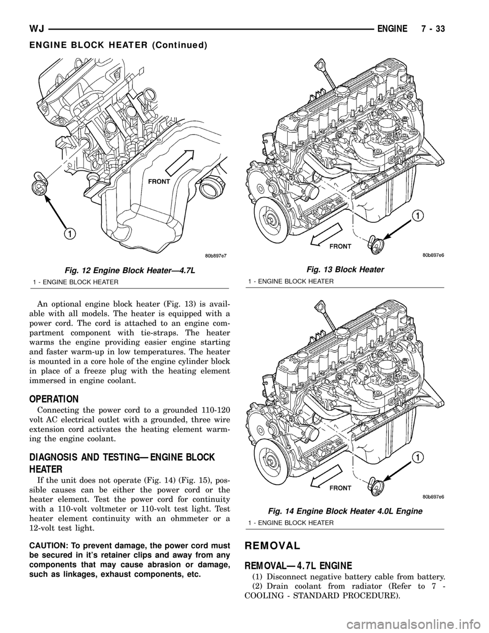
An optional engine block heater (Fig. 13) is avail-
able with all models. The heater is equipped with a
power cord. The cord is attached to an engine com-
partment component with tie-straps. The heater
warms the engine providing easier engine starting
and faster warm-up in low temperatures. The heater
is mounted in a core hole of the engine cylinder block
in place of a freeze plug with the heating element
immersed in engine coolant.
OPERATION
Connecting the power cord to a grounded 110-120
volt AC electrical outlet with a grounded, three wire
extension cord activates the heating element warm-
ing the engine coolant.
DIAGNOSIS AND TESTINGÐENGINE BLOCK
HEATER
If the unit does not operate (Fig. 14) (Fig. 15), pos-
sible causes can be either the power cord or the
heater element. Test the power cord for continuity
with a 110-volt voltmeter or 110-volt test light. Test
heater element continuity with an ohmmeter or a
12-volt test light.
CAUTION: To prevent damage, the power cord must
be secured in it's retainer clips and away from any
components that may cause abrasion or damage,
such as linkages, exhaust components, etc.
REMOVAL
REMOVALÐ4.7L ENGINE
(1) Disconnect negative battery cable from battery.
(2) Drain coolant from radiator (Refer to 7 -
COOLING - STANDARD PROCEDURE).
Fig. 12 Engine Block HeaterÐ4.7L
1 - ENGINE BLOCK HEATER
Fig. 13 Block Heater
1 - ENGINE BLOCK HEATER
Fig. 14 Engine Block Heater 4.0L Engine
1 - ENGINE BLOCK HEATER
WJENGINE 7 - 33
ENGINE BLOCK HEATER (Continued)
Page 257 of 2199

(3) Raise vehicle.
(4) Remove engine cylinder block drain plug(s)
located on the sides of cylinder block above the oil
pan rail (Fig. 16).
(5) Remove power cord from block heater.(6) Loosen screw at center of block heater. Remove
heater assembly (Fig. 17).
REMOVALÐ4.0L ENGINE
(1) Disconnect negative battery cable from battery.
(2) Drain coolant from radiator (Refer to 7 -
COOLING - STANDARD PROCEDURE).
(3) Raise vehicle.
(4) Remove engine cylinder block drain plug(s)
located on the sides of cylinder block above the oil
pan rail (Fig. 18).
(5) Remove power cord from block heater.
(6) Loosen screw at center of block heater. Remove
heater assembly (Fig. 19).
INSTALLATION
INSTALLATIONÐ4.7L ENGINE
(1) Thoroughly clean cylinder block core hole and
block heater seat.
(2) Insert block heater assembly with element loop
pointing at twelve o'clock (Fig. 17).
(3) With block heater fully seated, tighten center
screw to 2 N´m (17 in. lbs.) torque.
(4) Refill cooling system (Refer to 7 - COOLING -
STANDARD PROCEDURE).
(5) Start and warm the engine. Check for leaks.
INSTALLATIONÐ4.0L ENGINE
(1) Thoroughly clean cylinder block core hole and
block heater seat.
Fig. 15 Engine Block Heater 4.7L Engine
1 - ENGINE BLOCK HEATER
Fig. 16 Drain Plug - 4.7L Engine
1 - CYLINDER BLOCK DRAIN PLUG
2 - EXHAUST MANIFOLD AND HEAT SHIELD
Fig. 17 Engine Block Heater - 4.7L
1 - ENGINE BLOCK HEATER
7 - 34 ENGINEWJ
ENGINE BLOCK HEATER (Continued)