Vin JEEP GRAND CHEROKEE 2002 WJ / 2.G Owner's Manual
[x] Cancel search | Manufacturer: JEEP, Model Year: 2002, Model line: GRAND CHEROKEE, Model: JEEP GRAND CHEROKEE 2002 WJ / 2.GPages: 2199, PDF Size: 76.01 MB
Page 164 of 2199
(12) Install cover and tighten bolts in a criss-cross
pattern to 41 N´m (30 ft. lbs.).
(13) Refill the differential with Mopar Hypoid
Gear Lubricant or equivalent to bottom of the fill
plug hole.
(14) Install fill hole plug.
(15) Remove support and lower the vehicle.
DIFFERENTIAL - TRAC-LOK
DIAGNOSIS AND TESTING
The most common problem is a chatter noise when
turning corners. Before removing the unit for repair,
drain, flush and refill the axle with the specified
lubricant. A container of Mopar Trac-loktLubricant
(friction modifier) should be added after repair ser-
vice or during a lubricant change.
After changing the lubricant, drive the vehicle and
make 10 to 12 slow, figure-eight turns. This maneu-
ver will pump lubricant through the clutches. This
will correct the condition in most instances. If the
chatter persists, clutch damage could have occurred.
DIFFERENTIAL TEST
The differential can be tested without removing the
differential case by measuring rotating torque. Make
sure brakes are not dragging during this measure-
ment.
(1) Place blocks in front and rear of both front
wheels.
(2) Raise one rear wheel until it is completely off
the ground.
(3) Engine off, transmission in neutral, and park-
ing brake off.
(4) Remove wheel and bolt Special Tool 6790 or
equivalent tool to studs.
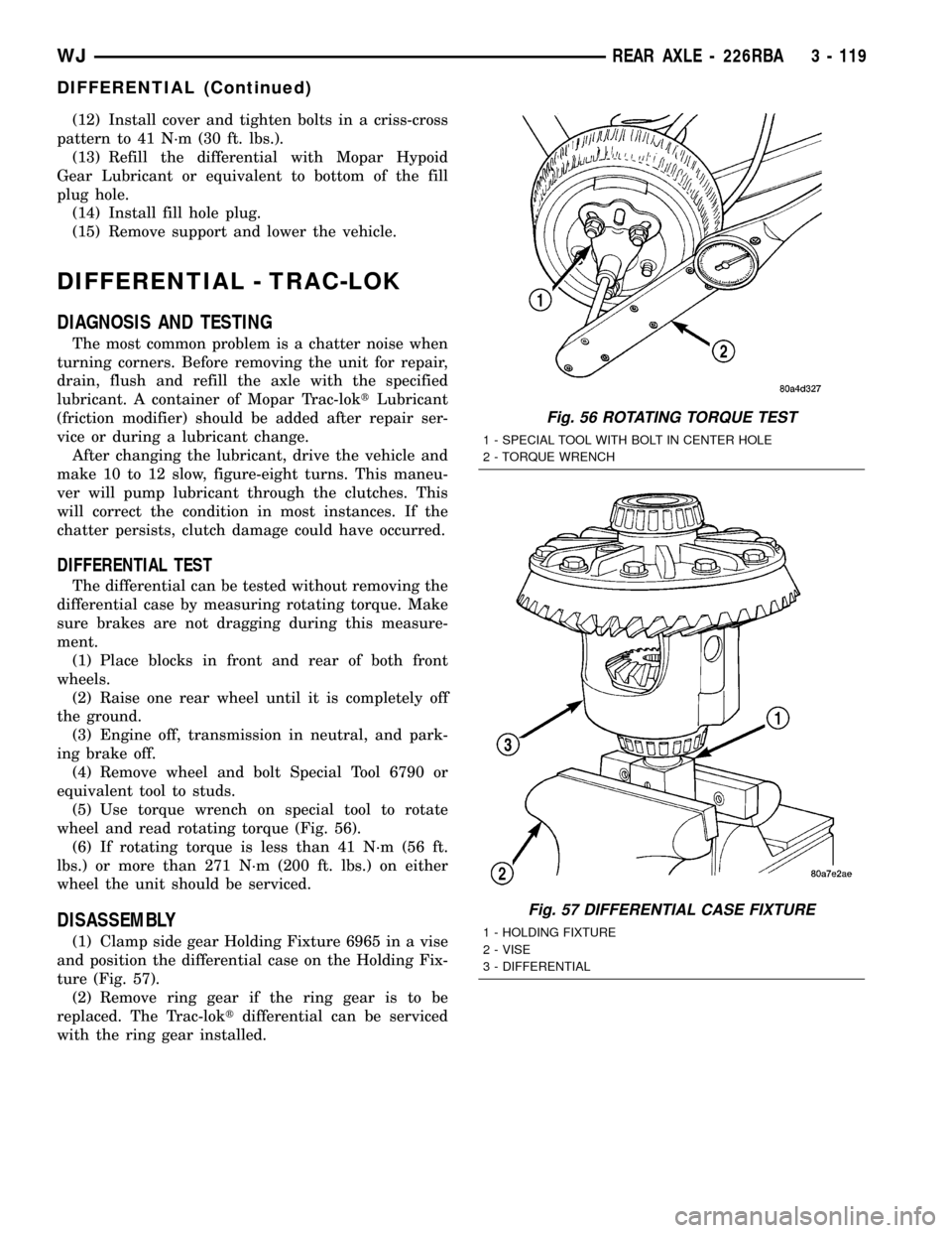
(5) Use torque wrench on special tool to rotate
wheel and read rotating torque (Fig. 56).
(6) If rotating torque is less than 41 N´m (56 ft.
lbs.) or more than 271 N´m (200 ft. lbs.) on either
wheel the unit should be serviced.
DISASSEMBLY
(1) Clamp side gear Holding Fixture 6965 in a vise
and position the differential case on the Holding Fix-
ture (Fig. 57).
(2) Remove ring gear if the ring gear is to be
replaced. The Trac-loktdifferential can be serviced
with the ring gear installed.
Fig. 56 ROTATING TORQUE TEST
1 - SPECIAL TOOL WITH BOLT IN CENTER HOLE
2 - TORQUE WRENCH
Fig. 57 DIFFERENTIAL CASE FIXTURE
1 - HOLDING FIXTURE
2 - VISE
3 - DIFFERENTIAL
WJREAR AXLE - 226RBA 3 - 119
DIFFERENTIAL (Continued)
Page 179 of 2199

Common causes of brake drag are:
²Parking brake partially applied.
²Loose/worn wheel bearing.
²Seized caliper.
²Caliper binding.
²Loose caliper mounting.
²Mis-assembled components.
²Damaged brake lines.
If brake drag occurs at the front, rear or all
wheels, the problem may be related to a blocked mas-
ter cylinder return port, faulty power booster (binds-
does not release) or the ABS system.
BRAKE FADE
Brake fade is usually a product of overheating
caused by brake drag. However, brake overheating
and resulting fade can also be caused by riding the
brake pedal, making repeated high deceleration stops
in a short time span, or constant braking on steep
mountain roads. Refer to the Brake Drag information
in this section for causes.
BRAKE PULL
Front brake pull condition could result from:
²Contaminated lining in one caliper
²Seized caliper piston
²Binding caliper
²Loose caliper
²Rusty caliper slide surfaces
²Improper brake shoes
²Damaged rotor
²Wheel alignment.
²Tire pressure.
A worn, damaged wheel bearing or suspension compo-
nent are further causes of pull. A damaged front tire
(bruised, ply separation) can also cause pull.
A common and frequently misdiagnosed pull condi-
tion is where direction of pull changes after a few
stops. The cause is a combination of brake drag fol-
lowed by fade at one of the brake units.
As the dragging brake overheats, efficiency is so
reduced that fade occurs. Since the opposite brake
unit is still functioning normally, its braking effect is
magnified. This causes pull to switch direction in
favor of the normally functioning brake unit.
An additional point when diagnosing a change in
pull condition concerns brake cool down. Remember
that pull will return to the original direction, if the
dragging brake unit is allowed to cool down (and is
not seriously damaged).
REAR BRAKE DRAG OR PULL
Rear drag or pull may be caused by improperly
adjusted park brake shoes or seized parking brake
cables, contaminated lining, bent or binding shoes or
improperly assembled components. This is particu-
larly true when only one rear wheel is involved.However, when both rear wheels are affected, the
master cylinder or ABS system could be at fault.
BRAKES DO NOT HOLD AFTER DRIVING THROUGH DEEP
WATER PUDDLES
This condition is generally caused by water soaked
lining. If the lining is only wet, it can be dried by
driving with the brakes very lightly applied for a
mile or two. However, if the lining is both soaked and
dirt contaminated, cleaning and or replacement will
be necessary.
BRAKE LINING CONTAMINATION
Brake lining contamination is mostly a product of
leaking calipers or worn seals, driving through deep
water puddles, or lining that has become covered with
grease and grit during repair. Contaminated lining
should be replaced to avoid further brake problems.
WHEEL AND TIRE PROBLEMS
Some conditions attributed to brake components
may actually be caused by a wheel or tire problem.
A damaged wheel can cause shudder, vibration and
pull. A worn or damaged tire can also cause pull.
NOTE: Propshaft angle can also cause vibration/
shudder.
Severely worn tires with very little tread left can
produce a grab-like condition as the tire loses and
recovers traction. Flat-spotted tires can cause vibra-
tion and generate shudder during brake operation.
Tire damage such as a severe bruise, cut, ply separa-
tion, low air pressure can cause pull and vibration.
BRAKE NOISES
Some brake noise is common on some disc brakes
during the first few stops after a vehicle has been
parked overnight or stored. This is primarily due to
the formation of trace corrosion (light rust) on metal
surfaces. This light corrosion is typically cleared from
the metal surfaces after a few brake applications
causing the noise to subside.
BRAKE SQUEAK/SQUEAL
Brake squeak or squeal may be due to linings that
are wet or contaminated with brake fluid, grease, or oil.
Glazed linings and rotors with hard spots can also con-
tribute to squeak. Dirt and foreign material embedded
in the brake lining will also cause squeak/squeal.
A very loud squeak or squeal is frequently a sign of
severely worn brake lining. If the lining has worn
through to the brake shoes in spots, metal-to-metal
contact occurs. If the condition is allowed to continue,
rotors may become so scored that replacement is nec-
essary.
5 - 4 BRAKES - BASEWJ
BRAKES - BASE (Continued)
Page 194 of 2199
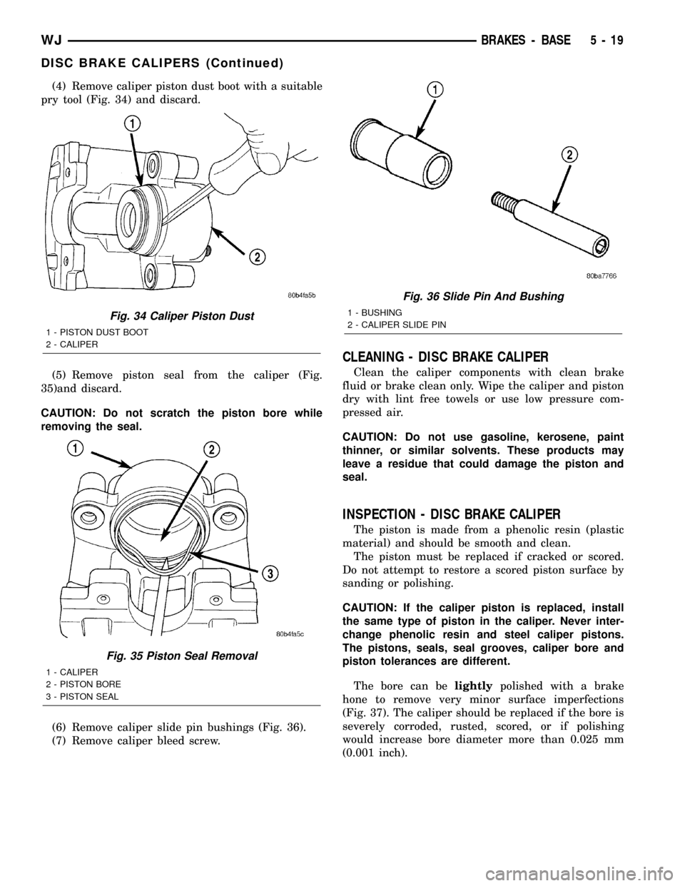
(4) Remove caliper piston dust boot with a suitable
pry tool (Fig. 34) and discard.
(5) Remove piston seal from the caliper (Fig.
35)and discard.
CAUTION: Do not scratch the piston bore while
removing the seal.
(6) Remove caliper slide pin bushings (Fig. 36).
(7) Remove caliper bleed screw.
CLEANING - DISC BRAKE CALIPER
Clean the caliper components with clean brake
fluid or brake clean only. Wipe the caliper and piston
dry with lint free towels or use low pressure com-
pressed air.
CAUTION: Do not use gasoline, kerosene, paint
thinner, or similar solvents. These products may
leave a residue that could damage the piston and
seal.
INSPECTION - DISC BRAKE CALIPER
The piston is made from a phenolic resin (plastic
material) and should be smooth and clean.
The piston must be replaced if cracked or scored.
Do not attempt to restore a scored piston surface by
sanding or polishing.
CAUTION: If the caliper piston is replaced, install
the same type of piston in the caliper. Never inter-
change phenolic resin and steel caliper pistons.
The pistons, seals, seal grooves, caliper bore and
piston tolerances are different.
The bore can belightlypolished with a brake
hone to remove very minor surface imperfections
(Fig. 37). The caliper should be replaced if the bore is
severely corroded, rusted, scored, or if polishing
would increase bore diameter more than 0.025 mm
(0.001 inch).
Fig. 34 Caliper Piston Dust
1 - PISTON DUST BOOT
2 - CALIPER
Fig. 35 Piston Seal Removal
1 - CALIPER
2 - PISTON BORE
3 - PISTON SEAL
Fig. 36 Slide Pin And Bushing
1 - BUSHING
2 - CALIPER SLIDE PIN
WJBRAKES - BASE 5 - 19
DISC BRAKE CALIPERS (Continued)
Page 207 of 2199
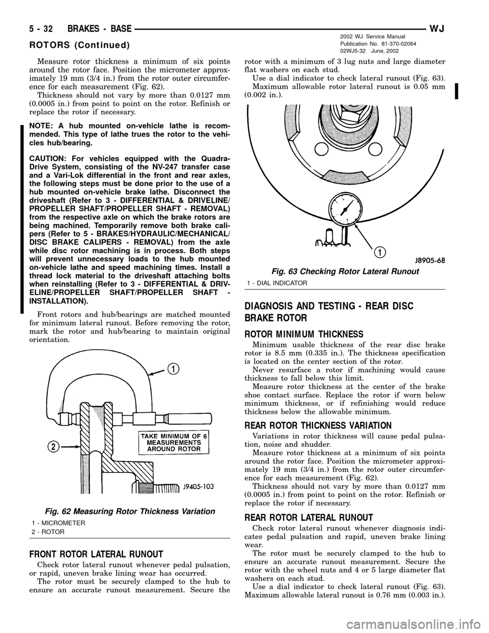
Measure rotor thickness a minimum of six points
around the rotor face. Position the micrometer approx-
imately 19 mm (3/4 in.) from the rotor outer circumfer-
ence for each measurement (Fig. 62).
Thickness should not vary by more than 0.0127 mm
(0.0005 in.) from point to point on the rotor. Refinish or
replace the rotor if necessary.
NOTE: A hub mounted on-vehicle lathe is recom-
mended. This type of lathe trues the rotor to the vehi-
cles hub/bearing.
CAUTION: For vehicles equipped with the Quadra-
Drive System, consisting of the NV-247 transfer case
and a Vari-Lok differential in the front and rear axles,
the following steps must be done prior to the use of a
hub mounted on-vehicle brake lathe. Disconnect the
driveshaft (Refer to 3 - DIFFERENTIAL & DRIVELINE/
PROPELLER SHAFT/PROPELLER SHAFT - REMOVAL)
from the respective axle on which the brake rotors are
being machined. Temporarily remove both brake cali-
pers (Refer to 5 - BRAKES/HYDRAULIC/MECHANICAL/
DISC BRAKE CALIPERS - REMOVAL) from the axle
while disc rotor machining is in process. Both steps
will prevent unnecessary loads to the hub mounted
on-vehicle lathe and speed machining times. Install a
thread lock material to the driveshaft attaching bolts
when reinstalling (Refer to 3 - DIFFERENTIAL & DRIV-
ELINE/PROPELLER SHAFT/PROPELLER SHAFT -
INSTALLATION).
Front rotors and hub/bearings are matched mounted
for minimum lateral runout. Before removing the rotor,
mark the rotor and hub/bearing to maintain original
orientation.
FRONT ROTOR LATERAL RUNOUT
Check rotor lateral runout whenever pedal pulsation,
or rapid, uneven brake lining wear has occurred.
The rotor must be securely clamped to the hub to
ensure an accurate runout measurement. Secure therotor with a minimum of 3 lug nuts and large diameter
flat washers on each stud.
Use a dial indicator to check lateral runout (Fig. 63).
Maximum allowable rotor lateral runout is 0.05 mm
(0.002 in.).
DIAGNOSIS AND TESTING - REAR DISC
BRAKE ROTOR
ROTOR MINIMUM THICKNESS
Minimum usable thickness of the rear disc brake
rotor is 8.5 mm (0.335 in.). The thickness specification
is located on the center section of the rotor.
Never resurface a rotor if machining would cause
thickness to fall below this limit.
Measure rotor thickness at the center of the brake
shoe contact surface. Replace the rotor if worn below
minimum thickness, or if refinishing would reduce
thickness below the allowable minimum.
REAR ROTOR THICKNESS VARIATION
Variations in rotor thickness will cause pedal pulsa-
tion, noise and shudder.
Measure rotor thickness at a minimum of six points
around the rotor face. Position the micrometer approxi-
mately 19 mm (3/4 in.) from the rotor outer circumfer-
ence for each measurement (Fig. 62).
Thickness should not vary by more than 0.0127 mm
(0.0005 in.) from point to point on the rotor. Refinish or
replace the rotor if necessary.
REAR ROTOR LATERAL RUNOUT
Check rotor lateral runout whenever diagnosis indi-
cates pedal pulsation and rapid, uneven brake lining
wear.
The rotor must be securely clamped to the hub to
ensure an accurate runout measurement. Secure the
rotor with the wheel nuts and 4 or 5 large diameter flat
washers on each stud.
Use a dial indicator to check lateral runout (Fig. 63).
Maximum allowable lateral runout is 0.76 mm (0.003 in.).
Fig. 62 Measuring Rotor Thickness Variation
1 - MICROMETER
2 - ROTOR
Fig. 63 Checking Rotor Lateral Runout
1 - DIAL INDICATOR
5 - 32 BRAKES - BASEWJ
ROTORS (Continued)
2002 WJ Service Manual
Publication No. 81-370-02064
02WJ5-32 June, 2002
Page 208 of 2199
STANDARD PROCEDURE - DISC ROTOR
MACHINING
CAUTION: For vehicles equipped with the Quadra-
Drive System, consisting of the NV-247 transfer case
and a Vari-Lok differential in the front and rear axles,
the following steps must be done prior to the use of a
hub mounted on-vehicle brake lathe. Disconnect the
driveshaft (Refer to 3 - DIFFERENTIAL & DRIVELINE/
PROPELLER SHAFT/PROPELLER SHAFT - REMOVAL)
from the respective axle on which the brake rotors are
being machined. Temporarily remove both brake cali-
pers (Refer to 5 - BRAKES/HYDRAULIC/MECHANICAL/
DISC BRAKE CALIPERS - REMOVAL) from the axle
while disc rotor machining is in process. Both steps
will prevent unnecessary loads to the hub mounted
on-vehicle lathe and speed machining times. Install a
thread lock material to the driveshaft attaching bolts
when reinstalling (Refer to 3 - DIFFERENTIAL & DRIV-
ELINE/PROPELLER SHAFT/PROPELLER SHAFT -
INSTALLATION).
NOTE: A hub mounted on-vehicle lathe is recom-
mended. This type of lathe trues the rotor to the vehi-
cles hub/bearing.
The disc brake rotor can be machined if scored or
worn. The lathe must machine both sides of the rotor
simultaneously with dual cutter heads. The rotor
mounting surface must be clean before placing on the
lathe. Equipment capable of machining only one side at
a time may produce a tapered rotor.
CAUTION: Brake rotors that do not meet minimum
thickness specifications before or after machining
must be replaced.
REMOVAL
REMOVAL - FRONT DISC BRAKE ROTOR
NOTE: Front rotors and hub/bearings are matched
mounted for minimum lateral runout. Before removing
the rotor, mark the rotor and hub/bearing to maintain
original orientation.
(1) Raise and support the vehicle.
(2) Remove wheel and tire assembly.
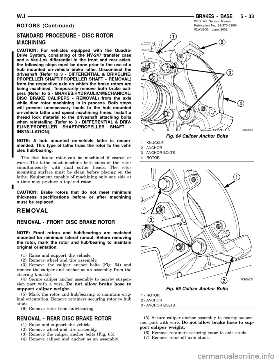
(3) Remove the caliper anchor bolts (Fig. 64) and
remove the caliper and anchor as an assembly from the
steering knuckle.
(4) Secure caliper anchor assembly to nearby suspen-
sion part with a wire.Do not allow brake hose to
support caliper weight.
(5) Mark the rotor and hub/bearing to maintain orig-
inal orientation. Remove retainers securing rotor to hub
studs.
(6) Remove rotor from hub/bearing.
REMOVAL - REAR DISC BRAKE ROTOR
(1) Raise and support the vehicle.
(2) Remove wheel and tire assembly.
(3) Remove the caliper anchor bolts (Fig. 65).
(4) Remove caliper and anchor as an assembly.(5) Secure caliper anchor assembly to nearby suspen-
sion part with wire.Do not allow brake hose to sup-
port caliper weight.
(6) Remove retainers securing rotor to axle studs.
(7) Remove rotor off axle studs.
Fig. 64 Caliper Anchor Bolts
1 - KNUCKLE
2 - ANCHOR
3 - ANCHOR BOLTS
4 - ROTOR
Fig. 65 Caliper Anchor Bolts
1 - ROTOR
2 - ANCHOR
3 - ANCHOR BOLTS
WJBRAKES - BASE 5 - 33
ROTORS (Continued)
2002 WJ Service Manual
Publication No. 81-370-02064
02WJ5-33 June, 2002
Page 217 of 2199
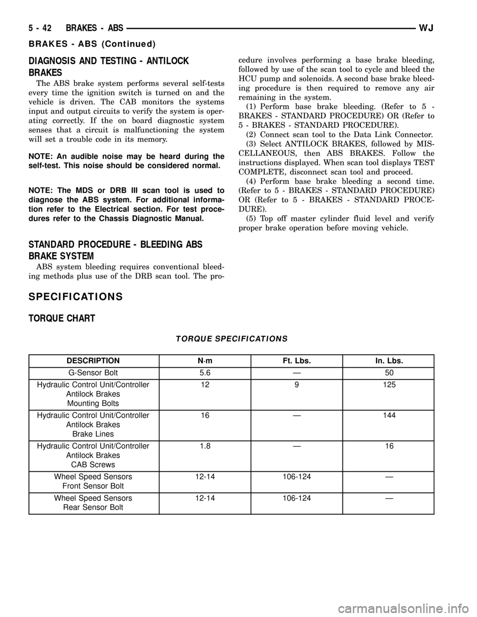
DIAGNOSIS AND TESTING - ANTILOCK
BRAKES
The ABS brake system performs several self-tests
every time the ignition switch is turned on and the
vehicle is driven. The CAB monitors the systems
input and output circuits to verify the system is oper-
ating correctly. If the on board diagnostic system
senses that a circuit is malfunctioning the system
will set a trouble code in its memory.
NOTE: An audible noise may be heard during the
self-test. This noise should be considered normal.
NOTE: The MDS or DRB III scan tool is used to
diagnose the ABS system. For additional informa-
tion refer to the Electrical section. For test proce-
dures refer to the Chassis Diagnostic Manual.
STANDARD PROCEDURE - BLEEDING ABS
BRAKE SYSTEM
ABS system bleeding requires conventional bleed-
ing methods plus use of the DRB scan tool. The pro-cedure involves performing a base brake bleeding,
followed by use of the scan tool to cycle and bleed the
HCU pump and solenoids. A second base brake bleed-
ing procedure is then required to remove any air
remaining in the system.
(1) Perform base brake bleeding. (Refer to 5 -
BRAKES - STANDARD PROCEDURE) OR (Refer to
5 - BRAKES - STANDARD PROCEDURE).
(2) Connect scan tool to the Data Link Connector.
(3) Select ANTILOCK BRAKES, followed by MIS-
CELLANEOUS, then ABS BRAKES. Follow the
instructions displayed. When scan tool displays TEST
COMPLETE, disconnect scan tool and proceed.
(4) Perform base brake bleeding a second time.
(Refer to 5 - BRAKES - STANDARD PROCEDURE)
OR (Refer to 5 - BRAKES - STANDARD PROCE-
DURE).
(5) Top off master cylinder fluid level and verify
proper brake operation before moving vehicle.
SPECIFICATIONS
TORQUE CHART
TORQUE SPECIFICATIONS
DESCRIPTION N´m Ft. Lbs. In. Lbs.
G-Sensor Bolt 5.6 Ð 50
Hydraulic Control Unit/Controller
Antilock Brakes
Mounting Bolts12 9 125
Hydraulic Control Unit/Controller
Antilock Brakes
Brake Lines16 Ð 144
Hydraulic Control Unit/Controller
Antilock Brakes
CAB Screws1.8 Ð 16
Wheel Speed Sensors
Front Sensor Bolt12-14 106-124 Ð
Wheel Speed Sensors
Rear Sensor Bolt12-14 106-124 Ð
5 - 42 BRAKES - ABSWJ
BRAKES - ABS (Continued)
Page 226 of 2199
The spring type hose clamp applies constant ten-
sion on a hose connection. To remove a spring type
hose clamp, only use constant tension clamp pliers
designed to compress the hose clamp.
DIAGNOSIS AND TESTING
DIAGNOSIS AND TESTINGÐON-BOARD
DIAGNOSTICS (OBD)
COOLING SYSTEM RELATED DIAGNOSTICS
The powertrain control module (PCM) has been
programmed to monitor certain cooling system com-
ponents:
²If the engine has remained cool for too long a
period, such as with a stuck open thermostat, a Diag-
nostic Trouble Code (DTC) can be set.
²If an open or shorted condition has developed in
the relay circuit controlling the electric radiator fan
or fan control solenoid circuit controling the hydrau-
lic fan, a Diagnostic Trouble Code (DTC) can be set.
If the problem is sensed in a monitored circuit
often enough to indicated an actual problem, a DTC
is stored. The DTC will be stored in the PCM mem-
ory for eventual display to the service technician.
(Refer to 25 - EMISSIONS CONTROL - DESCRIP-
TION).
ACCESSING DIAGNOSTIC TROUBLE CODES
To read DTC's and to obtain cooling system data,
(Refer to 25 - EMISSIONS CONTROL - DESCRIP-
TION).
ERASING TROUBLE CODES
After the problem has been repaired, use the DRB
scan tool to erase a DTC. Refer to the appropriate
Powertrain Diagnostic Procedures service informa-
tion for operation of the DRB scan tool.
DIAGNOSIS AND TESTINGÐPRELIMINARY
CHECKS
ENGINE COOLING SYSTEM OVERHEATING
Establish what driving conditions caused the com-
plaint. Abnormal loads on the cooling system such as
the following may be the cause:
²PROLONGED IDLE
²VERY HIGH AMBIENT TEMPERATURE
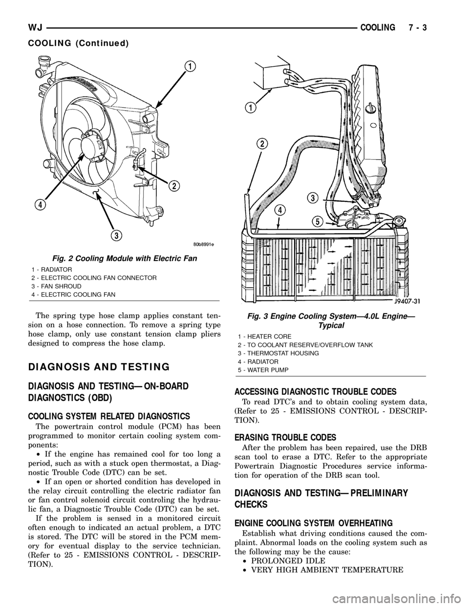
Fig. 2 Cooling Module with Electric Fan
1 - RADIATOR
2 - ELECTRIC COOLING FAN CONNECTOR
3 - FAN SHROUD
4 - ELECTRIC COOLING FAN
Fig. 3 Engine Cooling SystemÐ4.0L EngineÐ
Typical
1 - HEATER CORE
2 - TO COOLANT RESERVE/OVERFLOW TANK
3 - THERMOSTAT HOUSING
4 - RADIATOR
5 - WATER PUMP
WJCOOLING 7 - 3
COOLING (Continued)
Page 227 of 2199

²SLIGHT TAIL WIND AT IDLE
²SLOW TRAFFIC
²TRAFFIC JAMS
²HIGH SPEED
²STEEP GRADES
Driving techniques that avoid overheating are:
²Idle with A/C off when temperature gauge is at
end of normal range.
²Increase engine speed for more air flow is recom-
mended.(1) TRAILER TOWING:
Consult Trailer Towing section of owners manual.
Do not exceed limits.
(2) AIR CONDITIONING; ADD-ON OR AFTER
MARKET:
A maximum cooling package should have been
ordered with vehicle if add-on or after market A/C is
installed. If not, maximum cooling system compo-
nents should be installed for model involved per
manufacturer's specifications.
(3) RECENT SERVICE OR ACCIDENT REPAIR:
Determine if any recent service has been per-
formed on vehicle that may effect cooling system.
This may be:
²Engine adjustments (incorrect timing)
²Slipping engine accessory drive belt(s)
²Brakes (possibly dragging)
²Changed parts. Incorrect water pump, or pump
rotating in wrong direction due to belt not correctly
routed
²Reconditioned radiator or cooling system refill-
ing (possibly under filled or air trapped in system).
NOTE: If investigation reveals none of the previous
items as a cause for an engine overheating com-
plaint, refer to following Cooling System Diagnosis
charts.
These charts are to be used as a quick-reference
only. Refer to the group text for information.
Fig. 4 Spring Clamp Size Location
1 - SPRING CLAMP SIZE LOCATION
7 - 4 COOLINGWJ
COOLING (Continued)
Page 228 of 2199
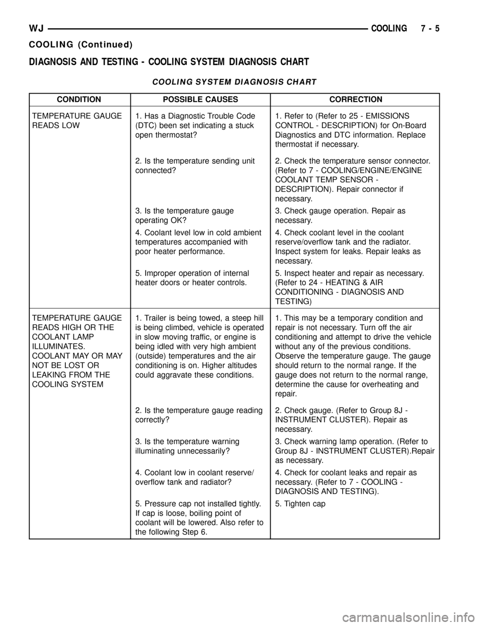
DIAGNOSIS AND TESTING - COOLING SYSTEM DIAGNOSIS CHART
COOLING SYSTEM DIAGNOSIS CHART
CONDITION POSSIBLE CAUSES CORRECTION
TEMPERATURE GAUGE
READS LOW1. Has a Diagnostic Trouble Code
(DTC) been set indicating a stuck
open thermostat?1. Refer to (Refer to 25 - EMISSIONS
CONTROL - DESCRIPTION) for On-Board
Diagnostics and DTC information. Replace
thermostat if necessary.
2. Is the temperature sending unit
connected?2. Check the temperature sensor connector.
(Refer to 7 - COOLING/ENGINE/ENGINE
COOLANT TEMP SENSOR -
DESCRIPTION). Repair connector if
necessary.
3. Is the temperature gauge
operating OK?3. Check gauge operation. Repair as
necessary.
4. Coolant level low in cold ambient
temperatures accompanied with
poor heater performance.4. Check coolant level in the coolant
reserve/overflow tank and the radiator.
Inspect system for leaks. Repair leaks as
necessary.
5. Improper operation of internal
heater doors or heater controls.5. Inspect heater and repair as necessary.
(Refer to 24 - HEATING & AIR
CONDITIONING - DIAGNOSIS AND
TESTING)
TEMPERATURE GAUGE
READS HIGH OR THE
COOLANT LAMP
ILLUMINATES.
COOLANT MAY OR MAY
NOT BE LOST OR
LEAKING FROM THE
COOLING SYSTEM1. Trailer is being towed, a steep hill
is being climbed, vehicle is operated
in slow moving traffic, or engine is
being idled with very high ambient
(outside) temperatures and the air
conditioning is on. Higher altitudes
could aggravate these conditions.1. This may be a temporary condition and
repair is not necessary. Turn off the air
conditioning and attempt to drive the vehicle
without any of the previous conditions.
Observe the temperature gauge. The gauge
should return to the normal range. If the
gauge does not return to the normal range,
determine the cause for overheating and
repair.
2. Is the temperature gauge reading
correctly?2. Check gauge. (Refer to Group 8J -
INSTRUMENT CLUSTER). Repair as
necessary.
3. Is the temperature warning
illuminating unnecessarily?3. Check warning lamp operation. (Refer to
Group 8J - INSTRUMENT CLUSTER).Repair
as necessary.
4. Coolant low in coolant reserve/
overflow tank and radiator?4. Check for coolant leaks and repair as
necessary. (Refer to 7 - COOLING -
DIAGNOSIS AND TESTING).
5. Pressure cap not installed tightly.
If cap is loose, boiling point of
coolant will be lowered. Also refer to
the following Step 6.5. Tighten cap
WJCOOLING 7 - 5
COOLING (Continued)
Page 234 of 2199
Carefully remove radiator pressure cap from filler
neck and check coolant level. Push down on cap to
disengage it from stop tabs. Wipe inside of filler neck
and examine lower inside sealing seat for nicks,
cracks, paint, dirt and solder residue. Inspect radia-
tor-to- reserve/overflow tank hose for internal
obstructions. Insert a wire through the hose to be
sure it is not obstructed.
Inspect cams on outside of filler neck. If cams are
damaged, seating of pressure cap valve and tester
seal will be affected.
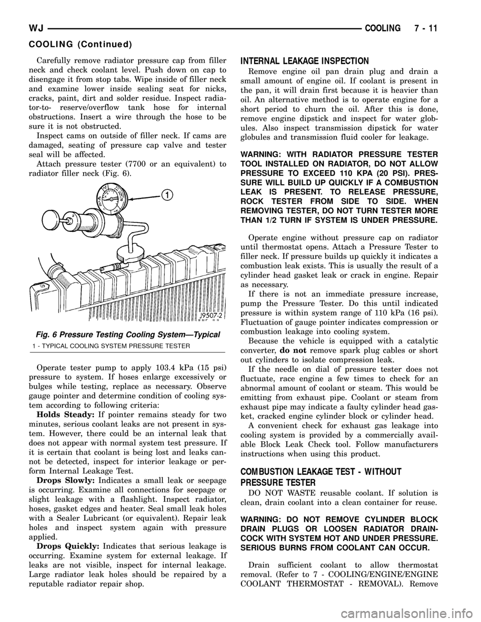
Attach pressure tester (7700 or an equivalent) to
radiator filler neck (Fig. 6).
Operate tester pump to apply 103.4 kPa (15 psi)
pressure to system. If hoses enlarge excessively or
bulges while testing, replace as necessary. Observe
gauge pointer and determine condition of cooling sys-
tem according to following criteria:
Holds Steady:If pointer remains steady for two
minutes, serious coolant leaks are not present in sys-
tem. However, there could be an internal leak that
does not appear with normal system test pressure. If
it is certain that coolant is being lost and leaks can-
not be detected, inspect for interior leakage or per-
form Internal Leakage Test.
Drops Slowly:Indicates a small leak or seepage
is occurring. Examine all connections for seepage or
slight leakage with a flashlight. Inspect radiator,
hoses, gasket edges and heater. Seal small leak holes
with a Sealer Lubricant (or equivalent). Repair leak
holes and inspect system again with pressure
applied.
Drops Quickly:Indicates that serious leakage is
occurring. Examine system for external leakage. If
leaks are not visible, inspect for internal leakage.
Large radiator leak holes should be repaired by a
reputable radiator repair shop.INTERNAL LEAKAGE INSPECTION
Remove engine oil pan drain plug and drain a
small amount of engine oil. If coolant is present in
the pan, it will drain first because it is heavier than
oil. An alternative method is to operate engine for a
short period to churn the oil. After this is done,
remove engine dipstick and inspect for water glob-
ules. Also inspect transmission dipstick for water
globules and transmission fluid cooler for leakage.
WARNING: WITH RADIATOR PRESSURE TESTER
TOOL INSTALLED ON RADIATOR, DO NOT ALLOW
PRESSURE TO EXCEED 110 KPA (20 PSI). PRES-
SURE WILL BUILD UP QUICKLY IF A COMBUSTION
LEAK IS PRESENT. TO RELEASE PRESSURE,
ROCK TESTER FROM SIDE TO SIDE. WHEN
REMOVING TESTER, DO NOT TURN TESTER MORE
THAN 1/2 TURN IF SYSTEM IS UNDER PRESSURE.
Operate engine without pressure cap on radiator
until thermostat opens. Attach a Pressure Tester to
filler neck. If pressure builds up quickly it indicates a
combustion leak exists. This is usually the result of a
cylinder head gasket leak or crack in engine. Repair
as necessary.
If there is not an immediate pressure increase,
pump the Pressure Tester. Do this until indicated
pressure is within system range of 110 kPa (16 psi).
Fluctuation of gauge pointer indicates compression or
combustion leakage into cooling system.
Because the vehicle is equipped with a catalytic
converter,do notremove spark plug cables or short
out cylinders to isolate compression leak.
If the needle on dial of pressure tester does not
fluctuate, race engine a few times to check for an
abnormal amount of coolant or steam. This would be
emitting from exhaust pipe. Coolant or steam from
exhaust pipe may indicate a faulty cylinder head gas-
ket, cracked engine cylinder block or cylinder head.
A convenient check for exhaust gas leakage into
cooling system is provided by a commercially avail-
able Block Leak Check tool. Follow manufacturers
instructions when using this product.
COMBUSTION LEAKAGE TEST - WITHOUT
PRESSURE TESTER
DO NOT WASTE reusable coolant. If solution is
clean, drain coolant into a clean container for reuse.
WARNING: DO NOT REMOVE CYLINDER BLOCK
DRAIN PLUGS OR LOOSEN RADIATOR DRAIN-
COCK WITH SYSTEM HOT AND UNDER PRESSURE.
SERIOUS BURNS FROM COOLANT CAN OCCUR.
Drain sufficient coolant to allow thermostat
removal. (Refer to 7 - COOLING/ENGINE/ENGINE
COOLANT THERMOSTAT - REMOVAL). Remove
Fig. 6 Pressure Testing Cooling SystemÐTypical
1 - TYPICAL COOLING SYSTEM PRESSURE TESTER
WJCOOLING 7 - 11
COOLING (Continued)