oil cap JEEP GRAND CHEROKEE 2002 WJ / 2.G Owner's Manual
[x] Cancel search | Manufacturer: JEEP, Model Year: 2002, Model line: GRAND CHEROKEE, Model: JEEP GRAND CHEROKEE 2002 WJ / 2.GPages: 2199, PDF Size: 76.01 MB
Page 276 of 2199
CAUTION: When installing the serpentine engine
accessory drive belt, the belt MUST be routed cor-
rectly. If not, the engine may overheat due to the
water pump rotating in the wrong direction. Refer to
the Belt Removal and Installtion in this group for
appropriate belt routing. You may also refer to the
Belt Routing Label in the vehicle engine compart-
ment.
Install accessory drive belt (Refer to 7 - COOLING/
ACCESSORY DRIVE/DRIVE BELTS - INSTALLA-
TION).
(6) Install fan blade and viscous fan drive onto
water pump.
(7) Fill cooling system with coolant and check for
leaks. (Refer to 7 - COOLING - STANDARD PROCE-
DURE).
(8) Connect battery cable to battery.
(9) Start and warm the engine. Check for leaks.
RADIATOR PRESSURE CAP
DESCRIPTION
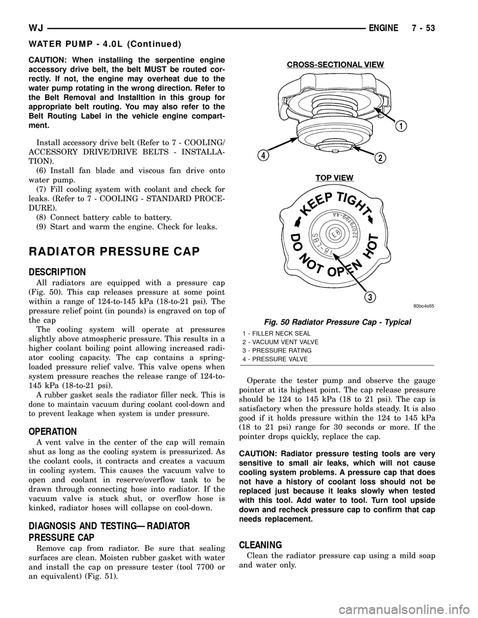
All radiators are equipped with a pressure cap
(Fig. 50). This cap releases pressure at some point
within a range of 124-to-145 kPa (18-to-21 psi). The
pressure relief point (in pounds) is engraved on top of
the cap
The cooling system will operate at pressures
slightly above atmospheric pressure. This results in a
higher coolant boiling point allowing increased radi-
ator cooling capacity. The cap contains a spring-
loaded pressure relief valve. This valve opens when
system pressure reaches the release range of 124-to-
145 kPa (18-to-21 psi).
A rubber gasket seals the radiator filler neck. This is
done to maintain vacuum during coolant cool-down and
to prevent leakage when system is under pressure.
OPERATION
A vent valve in the center of the cap will remain
shut as long as the cooling system is pressurized. As
the coolant cools, it contracts and creates a vacuum
in cooling system. This causes the vacuum valve to
open and coolant in reserve/overflow tank to be
drawn through connecting hose into radiator. If the
vacuum valve is stuck shut, or overflow hose is
kinked, radiator hoses will collapse on cool-down.
DIAGNOSIS AND TESTINGÐRADIATOR
PRESSURE CAP
Remove cap from radiator. Be sure that sealing
surfaces are clean. Moisten rubber gasket with water
and install the cap on pressure tester (tool 7700 or
an equivalent) (Fig. 51).Operate the tester pump and observe the gauge
pointer at its highest point. The cap release pressure
should be 124 to 145 kPa (18 to 21 psi). The cap is
satisfactory when the pressure holds steady. It is also
good if it holds pressure within the 124 to 145 kPa
(18 to 21 psi) range for 30 seconds or more. If the
pointer drops quickly, replace the cap.
CAUTION: Radiator pressure testing tools are very
sensitive to small air leaks, which will not cause
cooling system problems. A pressure cap that does
not have a history of coolant loss should not be
replaced just because it leaks slowly when tested
with this tool. Add water to tool. Turn tool upside
down and recheck pressure cap to confirm that cap
needs replacement.CLEANING
Clean the radiator pressure cap using a mild soap
and water only.
Fig. 50 Radiator Pressure Cap - Typical
1 - FILLER NECK SEAL
2 - VACUUM VENT VALVE
3 - PRESSURE RATING
4 - PRESSURE VALVE
WJENGINE 7 - 53
WATER PUMP - 4.0L (Continued)
Page 278 of 2199
TRANSMISSION
TABLE OF CONTENTS
page page
TRANS COOLER
DESCRIPTION.........................55STANDARD PROCEDURE - FLUSHING
COOLERS AND TUBES.................55
TRANS COOLER
DESCRIPTION
An internal high capacity/high efficiency cooler is
used on all vehicles these coolers are an oil-to-coolant
type which consists of plates mounted in the radiator
outlet tank (Fig. 36). Because the internal oil cooler
is so efficient, no auxiliary oil cooler is offered The
cooler is not servicable seperatly from the radiator.
STANDARD PROCEDURE - FLUSHING
COOLERS AND TUBES
When a transmission failure has contaminated the
fluid, the oil cooler(s) must be flushed. The torque
converter must also be replaced. This will insure that
metal particles or sludged oil are not later trans-
ferred back into the reconditioned (or replaced) trans-
mission.
The only recommended procedure for flushing cool-
ers and lines is to use Tool 6906-B Cooler Flusher.
WARNING: WEAR PROTECTIVE EYEWEAR THAT
MEETS THE REQUIREMENTS OF OSHA AND ANSI
Z87.1±1968. WEAR STANDARD INDUSTRIAL RUB-
BER GLOVES.
KEEP LIGHTED CIGARETTES, SPARKS, FLAMES,
AND OTHER IGNITION SOURCES AWAY FROM THE
AREA TO PREVENT THE IGNITION OF COMBUSTI-
BLE LIQUIDS AND GASES. KEEP A CLASS (B) FIRE
EXTINGUISHER IN THE AREA WHERE THE
FLUSHER WILL BE USED.
KEEP THE AREA WELL VENTILATED.
DO NOT LET FLUSHING SOLVENT COME IN CON-
TACT WITH YOUR EYES OR SKIN: IF EYE CONTAM-
INATION OCCURS, FLUSH EYES WITH WATER FOR
15 TO 20 SECONDS. REMOVE CONTAMINATED
CLOTHING AND WASH AFFECTED SKIN WITH
SOAP AND WATER. SEEK MEDICAL ATTENTION.
(1) Remove cover plate filler plug on Tool 6906-B.
Fill reservoir 1/2 to 3/4 full of fresh flushing solution.
Flushing solvents are petroleum based solutions gen-
erally used to clean automatic transmission compo-
nents.DO NOTuse solvents containing acids, water,
gasoline, or any other corrosive liquids.(2) Reinstall filler plug on Tool 6906-B.
(3) Verify pump power switch is turned OFF. Con-
nect red alligator clip to positive (+) battery post.
Connect black (-) alligator clip to a good ground.
(4) Disconnect the cooler lines at the transmission.
NOTE: When flushing transmission cooler and
lines, ALWAYS reverse flush.
NOTE: The converter drainback valve must be
removed and an appropriate replacement hose
installed to bridge the space between the transmis-
sion cooler line and the cooler fitting. Failure to
remove the drainback valve will prevent reverse
flushing the system. A suitable replacement hose
can be found in the adapter kit supplied with the
flushing tool.
(5) Connect the BLUE pressure line to the OUT-
LET (From) cooler line.
(6) Connect the CLEAR return line to the INLET
(To) cooler line
(7) Turn pump ON for two to three minutes to
flush cooler(s) and lines.
(8) Turn pump OFF.
(9) Disconnect CLEAR suction line from reservoir
at cover plate. Disconnect CLEAR return line at
cover plate, and place it in a drain pan.
(10) Turn pump ON for 30 seconds to purge flush-
ing solution from cooler and lines. Turn pump OFF.
(11) Place CLEAR suction line into a one quart
container of MopartATF +4, type 9602, Automatic
Transmission Fluid.
(12) Turn pump ON until all transmission fluid is
removed from the one quart container and lines. This
purges any residual cleaning solvent from the trans-
mission cooler and lines. Turn pump OFF.
(13) Disconnect alligator clips from battery. Recon-
nect flusher lines to cover plate, and remove flushing
adapters from cooler lines.
WJTRANSMISSION 7 - 55
Page 340 of 2199
to determine its cranking capacity. A battery that is
fully-charged, but does not pass the load test, is
faulty and must be replaced.
NOTE: Completely discharged batteries may take
several hours to accept a charge. Refer to Standard
Procedures for the proper battery charging proce-
dures.
STANDARD PROCEDURE
STANDARD PROCEDURE - BATTERY
CHARGING
Battery charging is the means by which the bat-
tery can be restored to its full voltage potential. A
battery is fully-charged when:
²Micro 420 electrical system tester indicates bat-
tery is OK.
²All of the battery cells are gassing freely during
battery charging.
²Three hydrometer tests, taken at one-hour inter-
vals, indicate no increase in the temperature-cor-
rected specific gravity of the battery electrolyte.
²Open-circuit voltage of the battery is 12.4 volts
or above.
WARNING: NEVER EXCEED TWENTY AMPERES
WHEN CHARGING A COLD (-1É C [30É F] OR
LOWER) BATTERY. THE BATTERY MAY ARC INTER-
NALLY AND EXPLODE. PERSONAL INJURY AND/OR
VEHICLE DAMAGE MAY RESULT.
WARNING: IF THE BATTERY SHOWS SIGNS OF
FREEZING, LEAKING, LOOSE POSTS, DO NOT
TEST, ASSIST-BOOST, OR CHARGE. THE BATTERY
MAY ARC INTERNALLY AND EXPLODE. PERSONAL
INJURY AND/OR VEHICLE DAMAGE MAY RESULT.
WARNING: EXPLOSIVE HYDROGEN GAS FORMS IN
AND AROUND THE BATTERY. DO NOT SMOKE,
USE FLAME, OR CREATE SPARKS NEAR THE BAT-
TERY. PERSONAL INJURY AND/OR VEHICLE DAM-
AGE MAY RESULT.
WARNING: THE BATTERY CONTAINS SULFURIC
ACID, WHICH IS POISONOUS AND CAUSTIC. AVOID
CONTACT WITH THE SKIN, EYES, OR CLOTHING.
IN THE EVENT OF CONTACT, FLUSH WITH WATER
AND CALL A PHYSICIAN IMMEDIATELY. KEEP OUT
OF THE REACH OF CHILDREN.WARNING: IF THE BATTERY IS EQUIPPED WITH
REMOVABLE CELL CAPS, BE CERTAIN THAT EACH
OF THE CELL CAPS IS IN PLACE AND TIGHT
BEFORE THE BATTERY IS RETURNED TO SER-
VICE. PERSONAL INJURY AND/OR VEHICLE DAM-
AGE MAY RESULT FROM LOOSE OR MISSING
CELL CAPS.
CAUTION: Always disconnect and isolate the bat-
tery negative cable before charging a battery. Do
not exceed sixteen volts while charging a battery.
Damage to the vehicle electrical system compo-
nents may result.
CAUTION: Battery electrolyte will bubble inside the
battery case during normal battery charging. Elec-
trolyte boiling or being discharged from the battery
vents indicates a battery overcharging condition.
Immediately reduce the charging rate or turn off the
charger to evaluate the battery condition. Damage
to the battery may result from overcharging.
CAUTION: The battery should not be hot to the
touch. If the battery feels hot to the touch, turn off
the charger and let the battery cool before continu-
ing the charging operation. Damage to the battery
may result.
After the battery has been charged to 12.4 volts or
greater, perform a load test to determine the battery
cranking capacity. Refer to Standard Procedures for
the proper battery load test procedures. If the battery
will endure a load test, return the battery to service.
If the battery will not endure a load test, it is faulty
and must be replaced.
Clean and inspect the battery hold downs, tray,
terminals, posts, and top before completing battery
service. Refer to Battery System Cleaning for the
proper battery system cleaning procedures, and Bat-
tery System Inspection for the proper battery system
inspection procedures.
CHARGING A COMPLETELY DISCHARGED
BATTERY
The following procedure should be used to recharge
a completely discharged battery. Unless this proce-
dure is properly followed, a good battery may be
needlessly replaced.
(1) Measure the voltage at the battery posts with a
voltmeter, accurate to 1/10 (0.10) volt (Fig. 5). If the
reading is below ten volts, the battery charging cur-
rent will be low. It could take some time before the
battery accepts a current greater than a few milliam-
peres. Such low current may not be detectable on the
ammeters built into many battery chargers.
WJBATTERY SYSTEM 8F - 9
BATTERY (Continued)
Page 369 of 2199
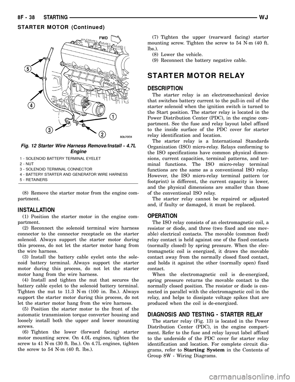
(8) Remove the starter motor from the engine com-
partment.
INSTALLATION
(1) Position the starter motor in the engine com-
partment.
(2) Reconnect the solenoid terminal wire harness
connector to the connector receptacle on the starter
solenoid. Always support the starter motor during
this process, do not let the starter motor hang from
the wire harness.
(3) Install the battery cable eyelet onto the sole-
noid battery terminal. Always support the starter
motor during this process, do not let the starter
motor hang from the wire harness.
(4) Install and tighten the nut that secures the
battery cable eyelet to the solenoid battery terminal.
Tighten the nut to 11.3 N´m (100 in. lbs.). Always
support the starter motor during this process, do not
let the starter motor hang from the wire harness.
(5) Position the starter motor to the front of the
automatic transmission torque converter housing and
loosely install both the upper and lower mounting
screws.
(6) Tighten the lower (forward facing) starter
motor mounting screw. On 4.0L engines, tighten the
screw to 41 N´m (30 ft. lbs.). On 4.7L engines, tighten
the screw to 54 N´m (40 ft. lbs.).(7) Tighten the upper (rearward facing) starter
mounting screw. Tighten the screw to 54 N´m (40 ft.
lbs.).
(8) Lower the vehicle.
(9) Reconnect the battery negative cable.
STARTER MOTOR RELAY
DESCRIPTION
The starter relay is an electromechanical device
that switches battery current to the pull-in coil of the
starter solenoid when the ignition switch is turned to
the Start position. The starter relay is located in the
Power Distribution Center (PDC), in the engine com-
partment. See the fuse and relay layout label affixed
to the inside surface of the PDC cover for starter
relay identification and location.
The starter relay is a International Standards
Organization (ISO) micro-relay. Relays conforming to
the ISO specifications have common physical dimen-
sions, current capacities, terminal patterns, and ter-
minal functions. The ISO micro-relay terminal
functions are the same as a conventional ISO relay.
However, the ISO micro-relay terminal pattern (or
footprint) is different, the current capacity is lower,
and the physical dimensions are smaller than those
of the conventional ISO relay.
The starter relay cannot be repaired or adjusted
and, if faulty or damaged, it must be replaced.
OPERATION
The ISO relay consists of an electromagnetic coil, a
resistor or diode, and three (two fixed and one mov-
able) electrical contacts. The movable (common feed)
relay contact is held against one of the fixed contacts
(normally closed) by spring pressure. When the elec-
tromagnetic coil is energized, it draws the movable
contact away from the normally closed fixed contact,
and holds it against the other (normally open) fixed
contact.
When the electromagnetic coil is de-energized,
spring pressure returns the movable contact to the
normally closed position. The resistor or diode is con-
nected in parallel with the electromagnetic coil in the
relay, and helps to dissipate voltage spikes that are
produced when the coil is de-energized.
DIAGNOSIS AND TESTING - STARTER RELAY
The starter relay (Fig. 13) is located in the Power
Distribution Center (PDC), in the engine compart-
ment. Refer to the fuse and relay layout label affixed
to the underside of the PDC cover for starter relay
identification and location. For complete circuit dia-
grams, refer toStarting Systemin the Contents of
Group 8W - Wiring Diagrams.
Fig. 12 Starter Wire Harness Remove/Install - 4.7L
Engine
1 - SOLENOID BATTERY TERMINAL EYELET
2 - NUT
3 - SOLENOID TERMINAL CONNECTOR
4 - BATTERY STARTER AND GENERATOR WIRE HARNESS
5 - RETAINERS
8F - 38 STARTINGWJ
STARTER MOTOR (Continued)
Page 376 of 2199
not attach the wire harness connectors until the cur-
ing process is complete.
(11) Check the operation of the rear glass heating
grid.
REAR WINDOW DEFOGGER
RELAY
DESCRIPTION
The rear window defogger relay is an electrome-
chanical device that switches fused battery current to
the rear glass heating grid and the Light-Emitting
Diode (LED) indicator of the rear window defogger
switch, when the Body Control Module (BCM) rear
window defogger timer and logic circuitry grounds
the relay coil. The rear window defogger relay is
located in the junction block, under the left end of
the instrument panel in the passenger compartment.
The rear window defogger relay is a International
Standards Organization (ISO) relay. Relays conform-
ing to the ISO specifications have common physical
dimensions, current capacities, terminal patterns,
and terminal functions.
The rear window defogger relay cannot be repaired
or adjusted and, if faulty or damaged, it must be
replaced.
OPERATION
The ISO relay consists of an electromagnetic coil, a
resistor or diode, and three (two fixed and one mov-
able) electrical contacts. The movable (common feed)
relay contact is held against one of the fixed contacts
(normally closed) by spring pressure. When the elec-
tromagnetic coil is energized, it draws the movable
contact away from the normally closed fixed contact,
and holds it against the other (normally open) fixed
contact.
When the electromagnetic coil is de-energized,
spring pressure returns the movable contact to the
normally closed position. The resistor or diode is con-
nected in parallel with the electromagnetic coil in the
relay, and helps to dissipate voltage spikes that are
produced when the coil is de-energized.
DIAGNOSIS AND TESTING - REAR WINDOW
DEFOGGER RELAY
WARNING: ON VEHICLES EQUIPPED WITH AIR-
BAGS, DISABLE THE AIRBAG SYSTEM BEFORE
ATTEMPTING ANY STEERING WHEEL, STEERING
COLUMN, OR INSTRUMENT PANEL COMPONENT
DIAGNOSIS OR SERVICE. DISCONNECT AND ISO-
LATE THE BATTERY NEGATIVE (GROUND) CABLE,
THEN WAIT TWO MINUTES FOR THE AIRBAG SYS-
TEM CAPACITOR TO DISCHARGE BEFORE PER-FORMING FURTHER DIAGNOSIS OR SERVICE. THIS
IS THE ONLY SURE WAY TO DISABLE THE AIRBAG
SYSTEM. FAILURE TO TAKE THE PROPER PRE-
CAUTIONS COULD RESULT IN AN ACCIDENTAL
AIRBAG DEPLOYMENT AND POSSIBLE PERSONAL
INJURY.
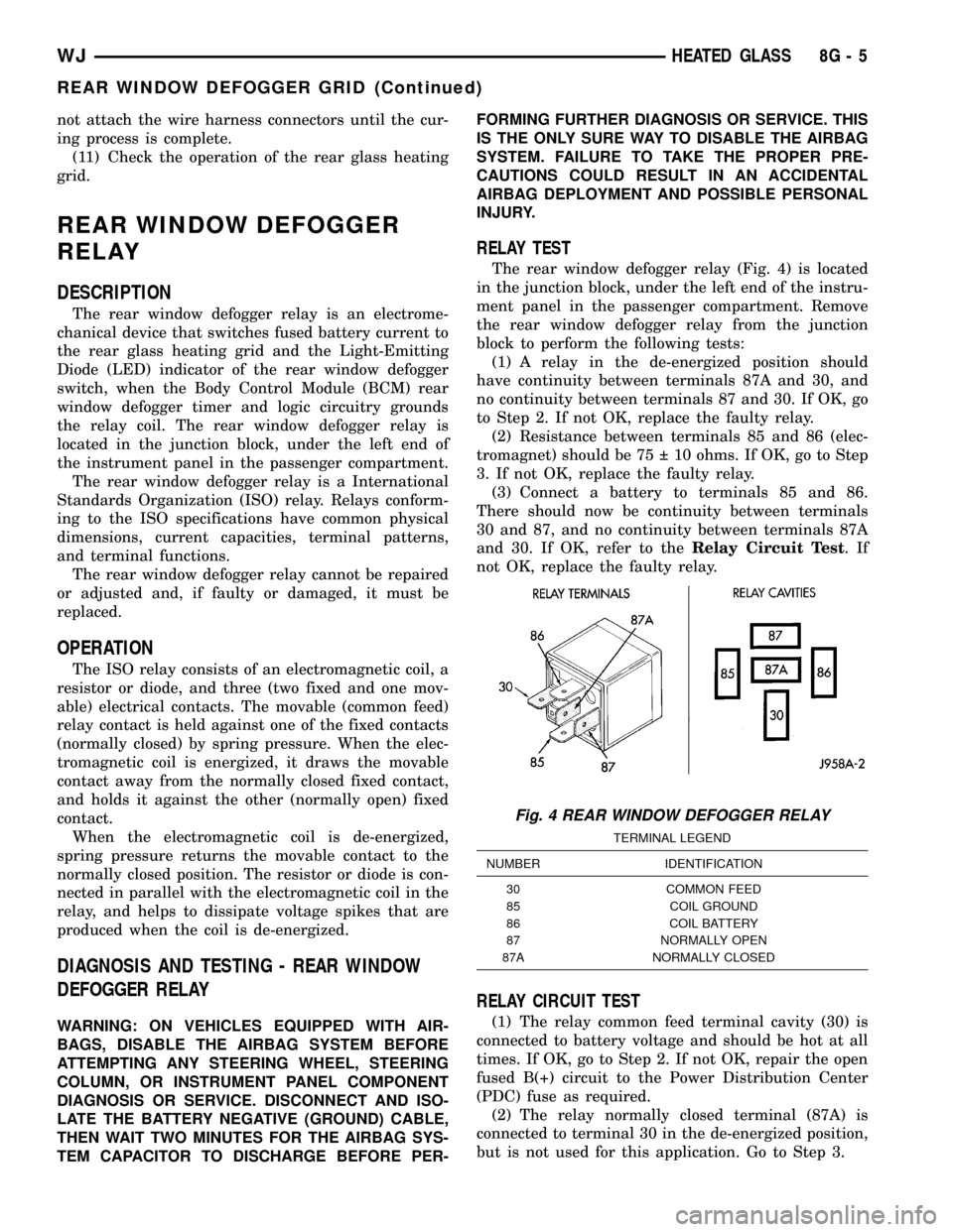
RELAY TEST
The rear window defogger relay (Fig. 4) is located
in the junction block, under the left end of the instru-
ment panel in the passenger compartment. Remove
the rear window defogger relay from the junction
block to perform the following tests:
(1) A relay in the de-energized position should
have continuity between terminals 87A and 30, and
no continuity between terminals 87 and 30. If OK, go
to Step 2. If not OK, replace the faulty relay.
(2) Resistance between terminals 85 and 86 (elec-
tromagnet) should be 75 10 ohms. If OK, go to Step
3. If not OK, replace the faulty relay.
(3) Connect a battery to terminals 85 and 86.
There should now be continuity between terminals
30 and 87, and no continuity between terminals 87A
and 30. If OK, refer to theRelay Circuit Test.If
not OK, replace the faulty relay.
RELAY CIRCUIT TEST
(1) The relay common feed terminal cavity (30) is
connected to battery voltage and should be hot at all
times. If OK, go to Step 2. If not OK, repair the open
fused B(+) circuit to the Power Distribution Center
(PDC) fuse as required.
(2) The relay normally closed terminal (87A) is
connected to terminal 30 in the de-energized position,
but is not used for this application. Go to Step 3.
Fig. 4 REAR WINDOW DEFOGGER RELAY
TERMINAL LEGEND
NUMBER IDENTIFICATION
30 COMMON FEED
85 COIL GROUND
86 COIL BATTERY
87 NORMALLY OPEN
87A NORMALLY CLOSED
WJHEATED GLASS 8G - 5
REAR WINDOW DEFOGGER GRID (Continued)
Page 377 of 2199
(3) The relay normally open terminal (87) is con-
nected to the common feed terminal (30) in the ener-
gized position. This terminal supplies battery voltage
to the rear glass heating grid and to the fuse in the
junction block that feeds the rear window defogger
switch LED indicator. There should be continuity
between the cavity for relay terminal 87 and the rear
glass heating grid and the rear window defogger
switch LED indicator at all times. If OK, go to Step
4. If not OK, repair the open rear window defogger
relay output circuit as required.
(4) The coil battery terminal (86) is connected to
the electromagnet in the relay. It is connected to bat-
tery voltage and should be hot at all times. Check for
battery voltage at the cavity for relay terminal 86. If
OK, go to Step 5. If not OK, repair the open fused
B(+) circuit to the PDC fuse as required.
(5) The coil ground terminal (85) is connected to
the electromagnet in the relay. This terminal is pro-
vided with ground by the Body Control Module
(BCM) rear window defogger timer and logic circuitry
to energize the defogger relay. There should be conti-
nuity to the rear window defogger relay control cir-
cuit cavity of the 22-way instrument panel wire
harness connector for the BCM. If OK, use a DRB
scan tool and refer to the Appropriate Diagnostic
Information to test the BCM. If not OK, repair the
open rear window defogger relay control circuit as
required.
REMOVAL
WARNING: ON VEHICLES EQUIPPED WITH AIR-
BAGS, DISABLE THE AIRBAG SYSTEM BEFORE
ATTEMPTING ANY STEERING WHEEL, STEERING
COLUMN, OR INSTRUMENT PANEL COMPONENT
DIAGNOSIS OR SERVICE. DISCONNECT AND ISO-
LATE THE BATTERY NEGATIVE (GROUND) CABLE,
THEN WAIT TWO MINUTES FOR THE AIRBAG SYS-
TEM CAPACITOR TO DISCHARGE BEFORE PER-
FORMING FURTHER DIAGNOSIS OR SERVICE. THIS
IS THE ONLY SURE WAY TO DISABLE THE AIRBAG
SYSTEM. FAILURE TO TAKE THE PROPER PRE-
CAUTIONS COULD RESULT IN AN ACCIDENTAL
AIRBAG DEPLOYMENT AND POSSIBLE PERSONAL
INJURY.
(1) Disconnect and isolate the battery negative
cable.
(2) Remove the steering column opening cover
from the instrument panel. Refer to Instrument
Panel System for the procedures.
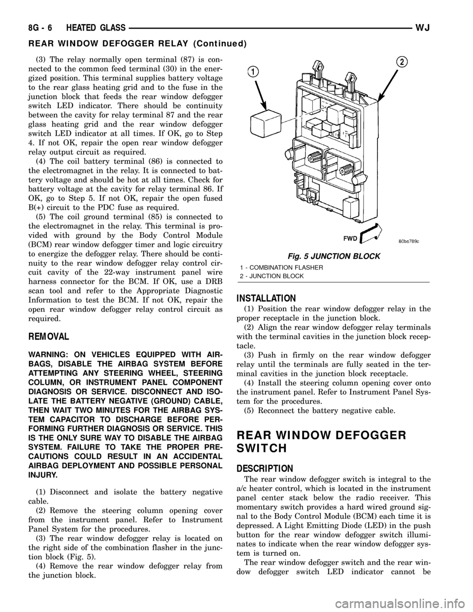
(3) The rear window defogger relay is located on
the right side of the combination flasher in the junc-
tion block (Fig. 5).
(4) Remove the rear window defogger relay from
the junction block.
INSTALLATION
(1) Position the rear window defogger relay in the
proper receptacle in the junction block.
(2) Align the rear window defogger relay terminals
with the terminal cavities in the junction block recep-
tacle.
(3) Push in firmly on the rear window defogger
relay until the terminals are fully seated in the ter-
minal cavities in the junction block receptacle.
(4) Install the steering column opening cover onto
the instrument panel. Refer to Instrument Panel Sys-
tem for the procedures.
(5) Reconnect the battery negative cable.
REAR WINDOW DEFOGGER
SWITCH
DESCRIPTION
The rear window defogger switch is integral to the
a/c heater control, which is located in the instrument
panel center stack below the radio receiver. This
momentary switch provides a hard wired ground sig-
nal to the Body Control Module (BCM) each time it is
depressed. A Light Emitting Diode (LED) in the push
button for the rear window defogger switch illumi-
nates to indicate when the rear window defogger sys-
tem is turned on.
The rear window defogger switch and the rear win-
dow defogger switch LED indicator cannot be
Fig. 5 JUNCTION BLOCK
1 - COMBINATION FLASHER
2 - JUNCTION BLOCK
8G - 6 HEATED GLASSWJ
REAR WINDOW DEFOGGER RELAY (Continued)
Page 393 of 2199
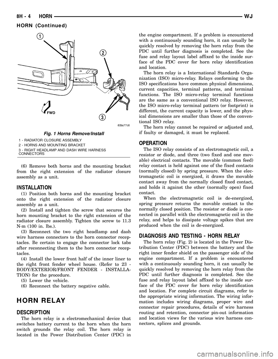
(6) Remove both horns and the mounting bracket
from the right extension of the radiator closure
assembly as a unit.
INSTALLATION
(1) Position both horns and the mounting bracket
onto the right extension of the radiator closure
assembly as a unit.
(2) Install and tighten the screw that secures the
horn mounting bracket to the right extension of the
radiator closure assembly. Tighten the screw to 11.3
N´m (100 in. lbs.).
(3) Reconnect the two right headlamp and dash
wire harness connectors to the horn connector recep-
tacles. Be certain to engage the connector lock tabs
after reconnecting them to the horn connector recep-
tacles.
(4) Install the lower front half of the inner liner to
the right front fender wheel house. (Refer to 23 -
BODY/EXTERIOR/FRONT FENDER - INSTALLA-
TION) for the procedure.
(5) Lower the vehicle.
(6) Reconnect the battery negative cable.
HORN RELAY
DESCRIPTION
The horn relay is a electromechanical device that
switches battery current to the horn when the horn
switch grounds the relay coil. The horn relay is
located in the Power Distribution Center (PDC) inthe engine compartment. If a problem is encountered
with a continuously sounding horn, it can usually be
quickly resolved by removing the horn relay from the
PDC until further diagnosis is completed. See the
fuse and relay layout label affixed to the inside sur-
face of the PDC cover for horn relay identification
and location.
The horn relay is a International Standards Orga-
nization (ISO) micro-relay. Relays conforming to the
ISO specifications have common physical dimensions,
current capacities, terminal patterns, and terminal
functions. The ISO micro-relay terminal functions
are the same as a conventional ISO relay. However,
the ISO micro-relay terminal pattern (or footprint) is
different, the current capacity is lower, and the phys-
ical dimensions are smaller than those of the conven-
tional ISO relay.
The horn relay cannot be repaired or adjusted and,
if faulty or damaged, it must be replaced.
OPERATION
The ISO relay consists of an electromagnetic coil, a
resistor or diode, and three (two fixed and one mov-
able) electrical contacts. The movable (common feed)
relay contact is held against one of the fixed contacts
(normally closed) by spring pressure. When the elec-
tromagnetic coil is energized, it draws the movable
contact away from the normally closed fixed contact,
and holds it against the other (normally open) fixed
contact.
When the electromagnetic coil is de-energized,
spring pressure returns the movable contact to the
normally closed position. The resistor or diode is con-
nected in parallel with the electromagnetic coil in the
relay, and helps to dissipate voltage spikes that are
produced when the coil is de-energized.
DIAGNOSIS AND TESTING - HORN RELAY
The horn relay (Fig. 2) is located in the Power Dis-
tribution Center (PDC) between the battery and the
right inner fender shield on the passenger side of the
engine compartment. If a problem is encountered
with a continuously sounding horn, it can usually be
quickly resolved by removing the horn relay from the
PDC until further diagnosis is completed. See the
fuse and relay layout label affixed to the inside sur-
face of the PDC cover for horn relay identification
and location. For complete circuit diagrams, refer to
the appropriate wiring information. The wiring infor-
mation includes wiring diagrams, proper wire and
connector repair procedures, details of wire harness
routing and retention, connector pin-out information
and location views for the various wire harness con-
nectors, splices and grounds.
Fig. 1 Horns Remove/Install
1 - RADIATOR CLOSURE ASSEMBLY
2 - HORNS AND MOUNTING BRACKET
3 - RIGHT HEADLAMP AND DASH WIRE HARNESS
CONNECTORS
8H - 4 HORNWJ
HORN (Continued)
Page 398 of 2199
IGNITION CONTROL
TABLE OF CONTENTS
page page
IGNITION CONTROL
DESCRIPTION..........................1
OPERATION............................1
SPECIFICATIONS
ENGINE FIRING ORDER - 4.0L 6-CYLINDER
ENGINE..............................2
ENGINE FIRING ORDERÐ4.7L V-8 ENGINE . . 2
IGNITION COIL RESISTANCE - 4.0L ENGINE . 2
IGNITION COIL RESISTANCEÐ4.7L V-8
ENGINE..............................2
IGNITION TIMING......................2
SPARK PLUGS........................3
TORQUE - IGNITION SYSTEM............3
AUTO SHUT DOWN RELAY
DESCRIPTION - PCM OUTPUT.............3
OPERATION
OPERATION - PCM OUTPUT.............3
OPERATION - ASD SENSE - PCM INPUT....4
REMOVAL.............................4
INSTALLATION..........................4
CAMSHAFT POSITION SENSOR
DESCRIPTION
DESCRIPTION - 4.0L....................4
DESCRIPTION - 4.7L....................5
OPERATION
OPERATION - 4.0L.....................5
OPERATION - 4.7L.....................5
REMOVAL
REMOVAL - 4.0L.......................6
REMOVAL - 4.7L.......................7INSTALLATION
INSTALLATION - 4.0L...................8
INSTALLATION - 4.7L...................9
COIL RAIL
DESCRIPTION..........................9
OPERATION...........................10
REMOVAL.............................10
INSTALLATION.........................11
IGNITION COIL
DESCRIPTION.........................11
OPERATION...........................12
REMOVAL.............................12
INSTALLATION.........................12
IGNITION COIL CAPACITOR
DESCRIPTION.........................13
OPERATION...........................13
REMOVAL.............................13
INSTALLATION.........................13
KNOCK SENSOR
DESCRIPTION.........................13
OPERATION...........................13
REMOVAL.............................14
INSTALLATION.........................15
SPARK PLUG
DESCRIPTION.........................15
DIAGNOSIS AND TESTING - SPARK PLUG
CONDITIONS.........................15
REMOVAL.............................18
CLEANING............................18
INSTALLATION.........................18
IGNITION CONTROL
DESCRIPTION
Two different ignition systems are used. One type
of system is for the 4.0L 6±cylinder engine. The other
is for the 4.7L V-8 engine.
OPERATION
The 4.0L 6±cylinder engine uses a one-piece coil
rail containing three independent coils. Although cyl-
inder firing order is the same as 4.0L engines of pre-
vious years, spark plug firing is not. The 3 coils dual-
fire the spark plugs on cylinders 1±6, 2±5 and/or 3±4.
When one cylinder is being fired (on compressionstroke), the spark to the opposite cylinder is being
wasted (on exhaust stroke). The one-piece coil bolts
directly to the cylinder head. Rubber boots seal the
secondary terminal ends of the coils to the top of all
6 spark plugs. One electrical connector (located at
the rear end of the coil rail) is used for all three coils.
The 4.7L V-8 engine uses 8 dedicated and individ-
ually fired coil for each spark plug. Each coil is
mounted directly to the top of each spark plug. A sep-
arate electrical connector is used for each coil.
Because of coil design, spark plug cables (second-
ary cables) are not used on either engine. Adistrib-
utor is not usedwith either the 4.0L or 4.7L
engines.
WJIGNITION CONTROL 8I - 1
Page 410 of 2199
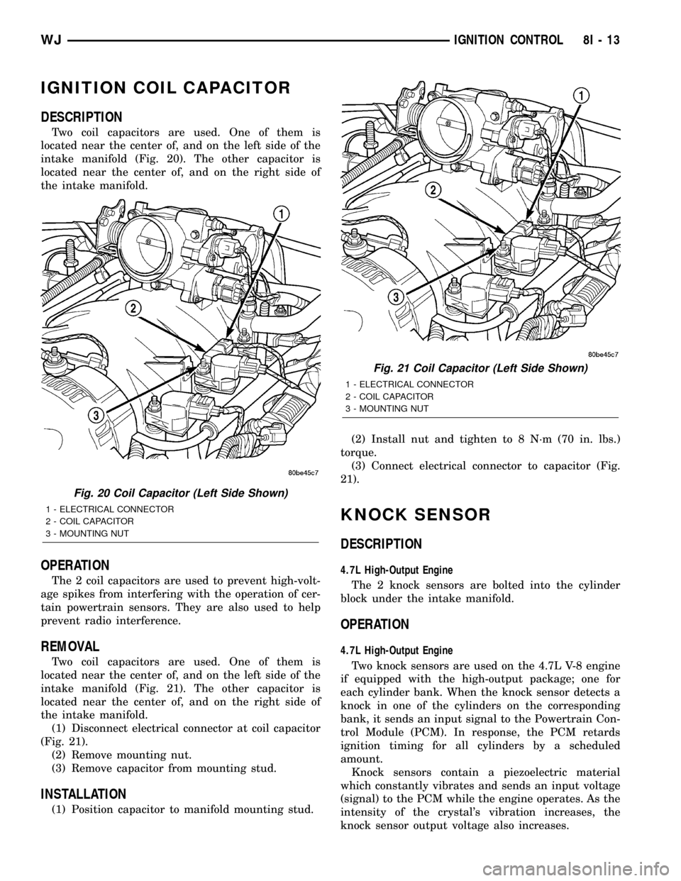
IGNITION COIL CAPACITOR
DESCRIPTION
Two coil capacitors are used. One of them is
located near the center of, and on the left side of the
intake manifold (Fig. 20). The other capacitor is
located near the center of, and on the right side of
the intake manifold.
OPERATION
The 2 coil capacitors are used to prevent high-volt-
age spikes from interfering with the operation of cer-
tain powertrain sensors. They are also used to help
prevent radio interference.
REMOVAL
Two coil capacitors are used. One of them is
located near the center of, and on the left side of the
intake manifold (Fig. 21). The other capacitor is
located near the center of, and on the right side of
the intake manifold.
(1) Disconnect electrical connector at coil capacitor
(Fig. 21).
(2) Remove mounting nut.
(3) Remove capacitor from mounting stud.
INSTALLATION
(1) Position capacitor to manifold mounting stud.(2) Install nut and tighten to 8 N´m (70 in. lbs.)
torque.
(3) Connect electrical connector to capacitor (Fig.
21).
KNOCK SENSOR
DESCRIPTION
4.7L High-Output Engine
The 2 knock sensors are bolted into the cylinder
block under the intake manifold.
OPERATION
4.7L High-Output Engine
Two knock sensors are used on the 4.7L V-8 engine
if equipped with the high-output package; one for
each cylinder bank. When the knock sensor detects a
knock in one of the cylinders on the corresponding
bank, it sends an input signal to the Powertrain Con-
trol Module (PCM). In response, the PCM retards
ignition timing for all cylinders by a scheduled
amount.
Knock sensors contain a piezoelectric material
which constantly vibrates and sends an input voltage
(signal) to the PCM while the engine operates. As the
intensity of the crystal's vibration increases, the
knock sensor output voltage also increases.
Fig. 20 Coil Capacitor (Left Side Shown)
1 - ELECTRICAL CONNECTOR
2 - COIL CAPACITOR
3 - MOUNTING NUT
Fig. 21 Coil Capacitor (Left Side Shown)
1 - ELECTRICAL CONNECTOR
2 - COIL CAPACITOR
3 - MOUNTING NUT
WJIGNITION CONTROL 8I - 13
Page 420 of 2199
certain conditions or inputs to provide the vehicle
operator with an audible alert to supplement a visual
indication.
The EMIC circuitry operates on battery current
received through fused B(+) fuses in the Power Dis-
tribution Center (PDC) and the Junction Block (JB)
on a non-switched fused B(+) circuit, and on battery
current received through a fused ignition switch out-
put (run-start) fuse in the JB on a fused ignition
switch output (run-start) circuit. This arrangement
allows the EMIC to provide some features regardless
of the ignition switch position, while other features
will operate only with the ignition switch in the On
or Start positions. The EMIC circuitry is grounded
through two separate ground circuits of the instru-
ment panel wire harness. These ground circuits
receive ground through take outs of the instrument
panel wire harness with eyelet terminal connectors
that are secured by a nut to a ground stud located on
the floor panel transmission tunnel beneath the cen-
ter floor console, just forward of the Airbag Control
Module (ACM).
The EMIC also has a self-diagnostic actuator test
capability, which will test each of the PCI bus mes-
sage-controlled functions of the cluster by lighting
the appropriate indicators (except the airbag indica-
tor), sweeping the gauge needles across the gauge
faces from their minimum to their maximum read-
ings, and stepping the odometer display sequentially
from all zeros through all nines. (Refer to 8 - ELEC-
TRICAL/INSTRUMENT CLUSTER - DIAGNOSIS
AND TESTING). The self-diagnostic actuator test
can be initialized manually or using a DRBIIItscan
tool. Refer to the appropriate diagnostic information.
See the owner's manual in the vehicle glove box for
more information on the features, use and operation
of the EMIC.
GAUGES
All gauges receive battery current through the
EMIC circuitry when the ignition switch is in the On
or Start positions. With the ignition switch in the Off
position battery current is not supplied to any
gauges, and the EMIC circuitry is programmed to
move all of the gauge needles back to the low end of
their respective scales. Therefore, the gauges do not
accurately indicate any vehicle condition unless the
ignition switch is in the On or Start positions. All of
the EMIC gauges, except the odometer, are air core
magnetic units. Two fixed electromagnetic coils are
located within each gauge. These coils are wrapped
at right angles to each other around a movable per-
manent magnet. The movable magnet is suspended
within the coils on one end of a pivot shaft, while the
gauge needle is attached to the other end of the
shaft. One of the coils has a fixed current flowingthrough it to maintain a constant magnetic field
strength. Current flow through the second coil
changes, which causes changes in its magnetic field
strength. The current flowing through the second coil
is changed by the EMIC circuitry in response to mes-
sages received over the PCI data bus. The gauge nee-
dle moves as the movable permanent magnet aligns
itself to the changing magnetic fields created around
it by the electromagnets.
The gauges are diagnosed using the EMIC self-di-
agnostic actuator test. (Refer to 8 - ELECTRICAL/
INSTRUMENT CLUSTER - DIAGNOSIS AND
TESTING). Proper testing of the PCI data bus, and
the data bus message inputs to the EMIC that con-
trol each gauge requires the use of a DRBIIItscan
tool. Refer to the appropriate diagnostic information.
Specific operation details for each gauge may be
found elsewhere in this service information.
VACUUM-FLUORESCENT DISPLAY
The Vacuum-Fluorescent Display (VFD) module is
soldered to the EMIC circuit board. The display is
active with the ignition switch in the On or Start
positions, and inactive when the ignition switch is in
any other position. The illumination intensity of the
VFD is controlled by the EMIC circuitry based upon
electronic dimming level messages received from the
BCM over the PCI data bus, and is synchronized
with the illumination intensity of other VFDs in the
vehicle. The BCM provides dimming level messages
based upon internal programming and inputs it
receives from the control knob and control ring on
the control stalk of the left (lighting) multi-function
switch on the steering column.
The VFD has several display capabilities including
odometer and trip odometer information. An odome-
ter/trip odometer switch on the EMIC circuit board is
used to control the display modes. This switch is
actuated manually by depressing the odometer/trip
odometer switch button that extends through the
lower edge of the cluster lens, just right of the speed-
ometer. Actuating this switch momentarily with the
ignition switch in the On position will toggle the
VFD between the odometer and trip odometer modes.
The EMIC microprocessor remembers which display
mode is active when the ignition switch is turned to
the Off position, and returns the display to that
mode when the ignition switch is turned On again.
Depressing the switch button for about two seconds
while the VFD is in the trip odometer mode will
reset the trip odometer value to zero. Holding this
switch depressed while turning the ignition switch
from the Off position to the On position will initiate
the EMIC self-diagnostic actuator test. Refer to the
appropriate diagnostic information for additional
details on this VFD function.
WJINSTRUMENT CLUSTER 8J - 5
INSTRUMENT CLUSTER (Continued)