Linkage JEEP GRAND CHEROKEE 2002 WJ / 2.G Owner's Guide
[x] Cancel search | Manufacturer: JEEP, Model Year: 2002, Model line: GRAND CHEROKEE, Model: JEEP GRAND CHEROKEE 2002 WJ / 2.GPages: 2199, PDF Size: 76.01 MB
Page 1540 of 2199
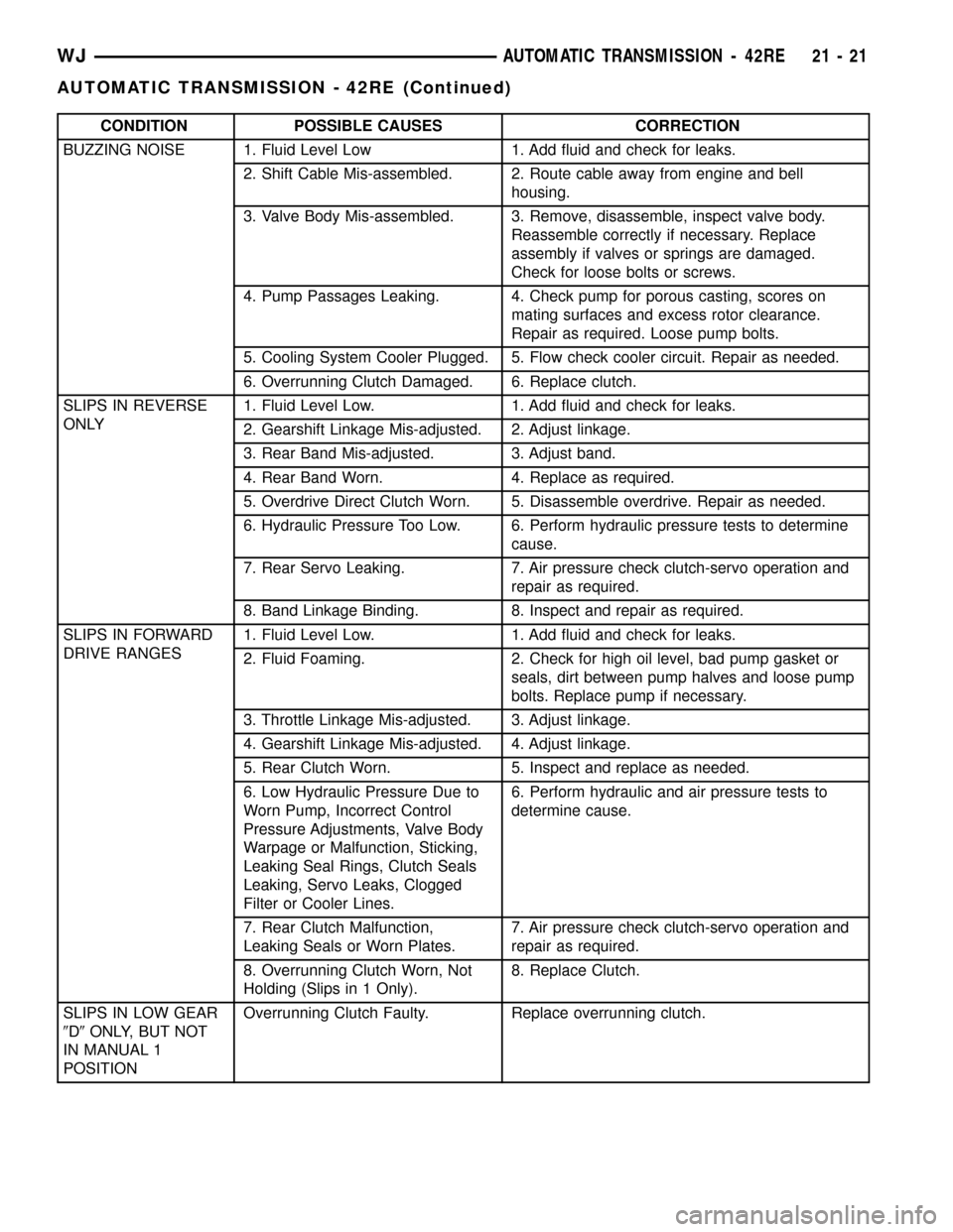
CONDITION POSSIBLE CAUSES CORRECTION
BUZZING NOISE 1. Fluid Level Low 1. Add fluid and check for leaks.
2. Shift Cable Mis-assembled. 2. Route cable away from engine and bell
housing.
3. Valve Body Mis-assembled. 3. Remove, disassemble, inspect valve body.
Reassemble correctly if necessary. Replace
assembly if valves or springs are damaged.
Check for loose bolts or screws.
4. Pump Passages Leaking. 4. Check pump for porous casting, scores on
mating surfaces and excess rotor clearance.
Repair as required. Loose pump bolts.
5. Cooling System Cooler Plugged. 5. Flow check cooler circuit. Repair as needed.
6. Overrunning Clutch Damaged. 6. Replace clutch.
SLIPS IN REVERSE
ONLY1. Fluid Level Low. 1. Add fluid and check for leaks.
2. Gearshift Linkage Mis-adjusted. 2. Adjust linkage.
3. Rear Band Mis-adjusted. 3. Adjust band.
4. Rear Band Worn. 4. Replace as required.
5. Overdrive Direct Clutch Worn. 5. Disassemble overdrive. Repair as needed.
6. Hydraulic Pressure Too Low. 6. Perform hydraulic pressure tests to determine
cause.
7. Rear Servo Leaking. 7. Air pressure check clutch-servo operation and
repair as required.
8. Band Linkage Binding. 8. Inspect and repair as required.
SLIPS IN FORWARD
DRIVE RANGES1. Fluid Level Low. 1. Add fluid and check for leaks.
2. Fluid Foaming. 2. Check for high oil level, bad pump gasket or
seals, dirt between pump halves and loose pump
bolts. Replace pump if necessary.
3. Throttle Linkage Mis-adjusted. 3. Adjust linkage.
4. Gearshift Linkage Mis-adjusted. 4. Adjust linkage.
5. Rear Clutch Worn. 5. Inspect and replace as needed.
6. Low Hydraulic Pressure Due to
Worn Pump, Incorrect Control
Pressure Adjustments, Valve Body
Warpage or Malfunction, Sticking,
Leaking Seal Rings, Clutch Seals
Leaking, Servo Leaks, Clogged
Filter or Cooler Lines.6. Perform hydraulic and air pressure tests to
determine cause.
7. Rear Clutch Malfunction,
Leaking Seals or Worn Plates.7. Air pressure check clutch-servo operation and
repair as required.
8. Overrunning Clutch Worn, Not
Holding (Slips in 1 Only).8. Replace Clutch.
SLIPS IN LOW GEAR
9D9ONLY, BUT NOT
IN MANUAL 1
POSITIONOverrunning Clutch Faulty. Replace overrunning clutch.
WJAUTOMATIC TRANSMISSION - 42RE 21 - 21
AUTOMATIC TRANSMISSION - 42RE (Continued)
Page 1541 of 2199
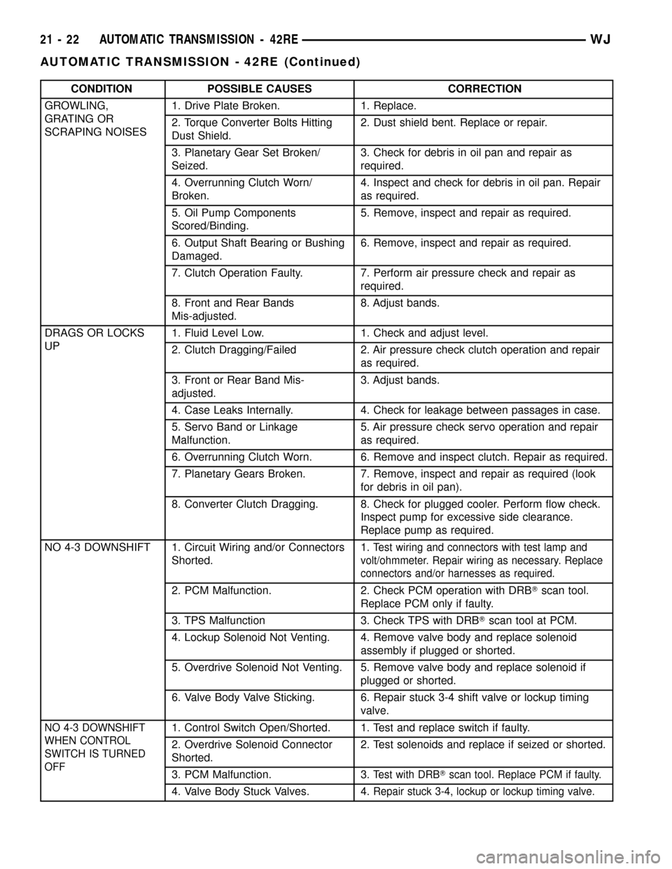
CONDITION POSSIBLE CAUSES CORRECTION
GROWLING,
GRATING OR
SCRAPING NOISES1. Drive Plate Broken. 1. Replace.
2. Torque Converter Bolts Hitting
Dust Shield.2. Dust shield bent. Replace or repair.
3. Planetary Gear Set Broken/
Seized.3. Check for debris in oil pan and repair as
required.
4. Overrunning Clutch Worn/
Broken.4. Inspect and check for debris in oil pan. Repair
as required.
5. Oil Pump Components
Scored/Binding.5. Remove, inspect and repair as required.
6. Output Shaft Bearing or Bushing
Damaged.6. Remove, inspect and repair as required.
7. Clutch Operation Faulty. 7. Perform air pressure check and repair as
required.
8. Front and Rear Bands
Mis-adjusted.8. Adjust bands.
DRAGS OR LOCKS
UP1. Fluid Level Low. 1. Check and adjust level.
2. Clutch Dragging/Failed 2. Air pressure check clutch operation and repair
as required.
3. Front or Rear Band Mis-
adjusted.3. Adjust bands.
4. Case Leaks Internally. 4. Check for leakage between passages in case.
5. Servo Band or Linkage
Malfunction.5. Air pressure check servo operation and repair
as required.
6. Overrunning Clutch Worn. 6. Remove and inspect clutch. Repair as required.
7. Planetary Gears Broken. 7. Remove, inspect and repair as required (look
for debris in oil pan).
8. Converter Clutch Dragging. 8. Check for plugged cooler. Perform flow check.
Inspect pump for excessive side clearance.
Replace pump as required.
NO 4-3 DOWNSHIFT 1. Circuit Wiring and/or Connectors
Shorted.1.
Test wiring and connectors with test lamp and
volt/ohmmeter. Repair wiring as necessary. Replace
connectors and/or harnesses as required.
2. PCM Malfunction. 2. Check PCM operation with DRBTscan tool.
Replace PCM only if faulty.
3. TPS Malfunction 3. Check TPS with DRBTscan tool at PCM.
4. Lockup Solenoid Not Venting. 4. Remove valve body and replace solenoid
assembly if plugged or shorted.
5. Overdrive Solenoid Not Venting. 5. Remove valve body and replace solenoid if
plugged or shorted.
6. Valve Body Valve Sticking. 6. Repair stuck 3-4 shift valve or lockup timing
valve.
NO 4-3 DOWNSHIFT
WHEN CONTROL
SWITCH IS TURNED
OFF1. Control Switch Open/Shorted. 1. Test and replace switch if faulty.
2. Overdrive Solenoid Connector
Shorted.2. Test solenoids and replace if seized or shorted.
3. PCM Malfunction. 3.
Test with DRBTscan tool. Replace PCM if faulty.
4. Valve Body Stuck Valves. 4.Repair stuck 3-4, lockup or lockup timing valve.
21 - 22 AUTOMATIC TRANSMISSION - 42REWJ
AUTOMATIC TRANSMISSION - 42RE (Continued)
Page 1544 of 2199
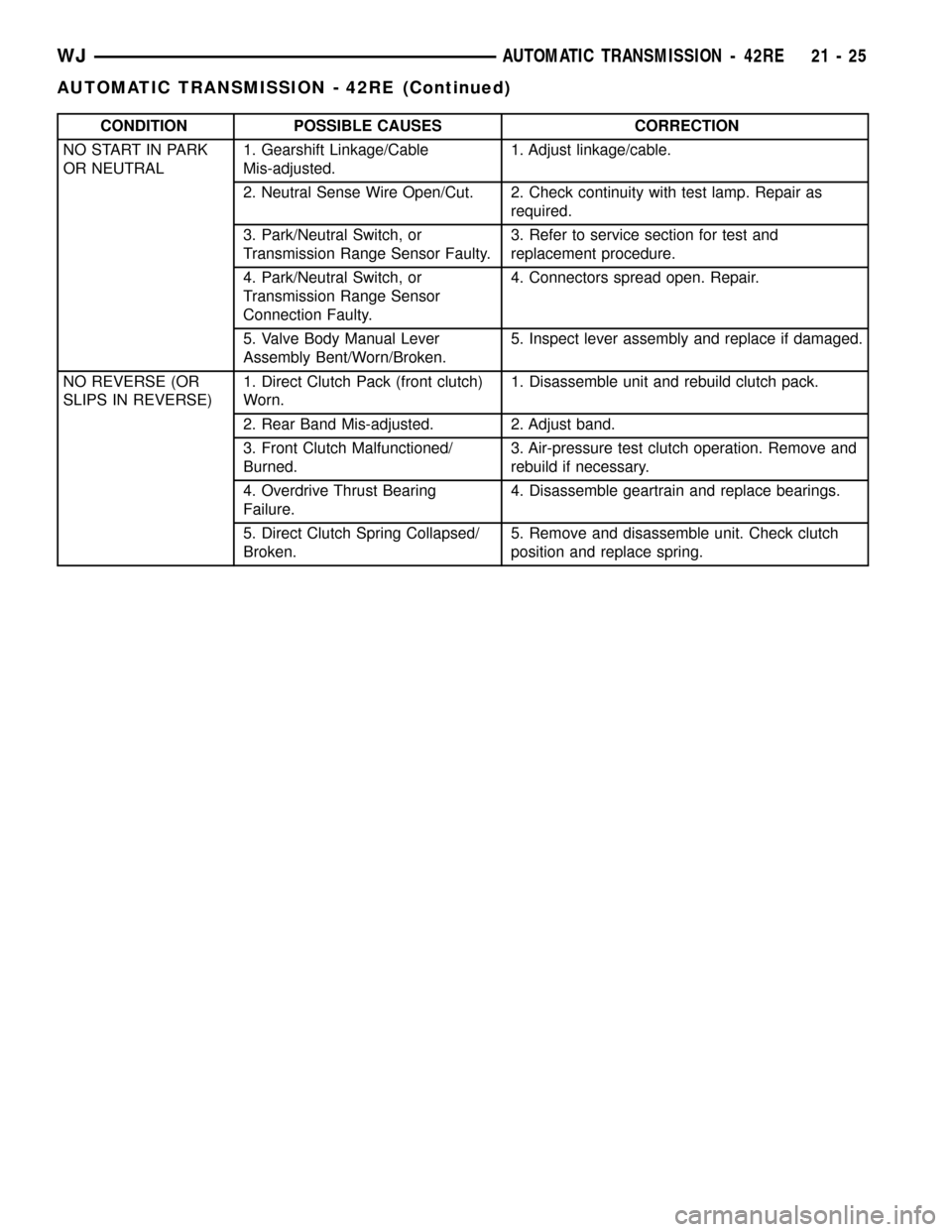
CONDITION POSSIBLE CAUSES CORRECTION
NO START IN PARK
OR NEUTRAL1. Gearshift Linkage/Cable
Mis-adjusted.1. Adjust linkage/cable.
2. Neutral Sense Wire Open/Cut. 2. Check continuity with test lamp. Repair as
required.
3. Park/Neutral Switch, or
Transmission Range Sensor Faulty.3. Refer to service section for test and
replacement procedure.
4. Park/Neutral Switch, or
Transmission Range Sensor
Connection Faulty.4. Connectors spread open. Repair.
5. Valve Body Manual Lever
Assembly Bent/Worn/Broken.5. Inspect lever assembly and replace if damaged.
NO REVERSE (OR
SLIPS IN REVERSE)1. Direct Clutch Pack (front clutch)
Worn.1. Disassemble unit and rebuild clutch pack.
2. Rear Band Mis-adjusted. 2. Adjust band.
3. Front Clutch Malfunctioned/
Burned.3. Air-pressure test clutch operation. Remove and
rebuild if necessary.
4. Overdrive Thrust Bearing
Failure.4. Disassemble geartrain and replace bearings.
5. Direct Clutch Spring Collapsed/
Broken.5. Remove and disassemble unit. Check clutch
position and replace spring.
WJAUTOMATIC TRANSMISSION - 42RE 21 - 25
AUTOMATIC TRANSMISSION - 42RE (Continued)
Page 1558 of 2199

(23) Check seal rings on reaction shaft support
hub. Verify that seal rings are hooked together and
that the thrust washer is properly positioned (Fig.
55). Use petroleum jelly to hold thrust washer in
place if necessary.(24) Lubricate oil pump body seal with petroleum
jelly. Lubricate pump shaft seal lip with petroleum
jelly.
(25) Thread two Pilot Stud Tools C-3288-B into
bolt holes in oil pump bore flange (Fig. 56).
(26) Align and install oil pump gasket (Fig. 56).
Fig. 53 Installing Front/Rear Clutch Assemblies
1 - INPUT SHAFT
2 - FRONT CLUTCH
3 - REAR CLUTCH
Fig. 54 Front Band Linkage Installation
1 - BAND LEVER
2 - BAND STRUT
3 - FRONT BAND
Fig. 55 Reaction Shaft Support Seal Rings And
Thrust Washer
1 - REACTION SHAFT SUPPORT HUB
2 - THRUST WASHER
3 - SEAL RINGS
Fig. 56 Installing Pilot Studs And Oil Pump Gasket
1 - OIL PUMP GASKET
2 - PILOT STUD TOOLS C-3288-B
WJAUTOMATIC TRANSMISSION - 42RE 21 - 39
AUTOMATIC TRANSMISSION - 42RE (Continued)
Page 1561 of 2199

(11) Move transmission forward. Then raise, lower
or tilt transmission to align converter housing with
engine block dowels.
(12) Carefully work transmission forward and over
engine block dowels until converter hub is seated in
crankshaft.
(13) Install two bolts to attach converter housing
to engine.
(14) Install the upper transmission bending braces
to the torque converter housing and the overdrive
unit. Tighten the bolts to 41 N´m (30 ft.lbs.).
(15) Install remaining torque converter housing to
engine bolts. Tighten to 68 N´m (50 ft.lbs.).
(16) Install rear transmission crossmember.
Tighten crossmember to frame bolts to 68 N´m (50
ft.lbs.).
(17) Install rear support to transmission. Tighten
bolts to 47 N´m (35 ft.lbs.).
(18) Lower transmission onto crossmember and
install bolts attaching transmission mount to cross-
member. Tighten clevis bracket to crossmember bolts
to 47 N´m (35 ft.lbs.). Tighten the clevis bracket to
rear support bolt to 68 N´m (50 ft.lbs.).
(19) Remove engine support fixture.
(20) Install crankshaft position sensor. (Refer to 14
- FUEL SYSTEM/FUEL INJECTION/CRANKSHAFT
POSITION SENSOR - INSTALLATION)
(21) Install new plastic retainer grommet on any
shift cable that was disconnected. Grommets should
not be reused. Use pry tool to remove rod from grom-
met and cut away old grommet. Use pliers to snap
new grommet into cable and to snap grommet onto
lever.
(22) Connect gearshift and throttle valve cable to
transmission.
(23) Connect wires to park/neutral position switch
and transmission solenoid connector. Be sure trans-
mission harnesses are properly routed.CAUTION: It is essential that correct length bolts be
used to attach the converter to the driveplate. Bolts
that are too long will damage the clutch surface
inside the converter.
(24) Install all torque converter-to-driveplate bolts
by hand.
(25) Verify that the torque converter is pulled
flush to the driveplate. Tighten bolts to 31 N´m (270
in. lbs.).
(26) Install converter housing access cover. Tighten
bolt to 23 N´m (200 in.lbs.).
(27) Install the bell housing brace to the torque
converter cover and the engine to transmission bend-
ing brace. Tighten the bolts and nut to 41 N´m (30
ft.lbs.).
(28) Install starter motor (Refer to 8 - ELECTRI-
CAL/STARTING/STARTER MOTOR - INSTALLA-
TION) and cooler line bracket.
(29) Connect cooler lines to transmission.
(30) Install transmission fill tube. Install new seal
on tube before installation.
(31) Install exhaust components.
(32) Install transfer case. Tighten transfer case
nuts to 35 N´m (26 ft.lbs.).
(33) Install the transfer case shift cable to the
cable support bracket and the transfer case shift
lever.
(34) Align and connect propeller shaft(s).
(35) Adjust gearshift linkage and throttle valve
cable if necessary.
(36) Lower vehicle.
(37) Fill transmission with MopartATF +4, type
9602, fluid.
21 - 42 AUTOMATIC TRANSMISSION - 42REWJ
AUTOMATIC TRANSMISSION - 42RE (Continued)
Page 1628 of 2199

PARK/NEUTRAL POSITION
SWITCH
DIAGNOSIS AND TESTING - PARK/NEUTRAL
POSITION SWITCH
The center terminal of the park/neutral position
switch is the starter-circuit terminal. It provides the
ground for the starter solenoid circuit through the
selector lever in PARK and NEUTRAL positions only.
The outer terminals on the switch are for the backup
lamp circuit.
SWITCH TEST
To test the switch, remove the wiring connector.
Test for continuity between the center terminal and
the transmission case. Continuity should exist only
when the transmission is in PARK or NEUTRAL.Shift the transmission into REVERSE and test
continuity at the switch outer terminals. Continuity
should exist only when the transmission is in
REVERSE. Continuity should not exist between the
outer terminals and the case.
Check gearshift linkage adjustment before replac-
ing a switch that tests faulty.
REMOVAL
(1) Raise vehicle and position drain pan under
switch.
(2) Disconnect switch wires.
(3) Remove switch from case.
INSTALLATION
(1) Move shift lever to PARK and NEUTRAL posi-
tions. Verify that switch operating lever fingers are
centered in switch opening in case (Fig. 198).
Fig. 197 Brake Transmission Shift Interlock
1 - SHIFT MECHANISM 4 - STEERING COLUMN ASSEMBLY
2 - SHIFTER BTSI LEVER 5 - INTERLOCK CABLE
3 - ADJUSTMENT CLIP
WJAUTOMATIC TRANSMISSION - 42RE 21 - 109
PARK LOCK CABLE (Continued)
Page 1647 of 2199

NOTE: Be sure that as the cable is pulled forward
and centered on the throttle lever stud, the cable
housing moves smoothly with the cable. Due to the
angle at which the cable housing enters the spring
housing, the cable housing may bind slightly and
create an incorrect adjustment.
(8) Reconnect the T.V. cable (B) to the throttle
bellcrank lever (C).
(9) Check cable adjustment. Verify transmission
throttle lever and lever on throttle body move simul-
taneously.
TORQUE CONVERTER
DESCRIPTION
The torque converter (Fig. 245) is a hydraulic
device that couples the engine crankshaft to the
transmission. The torque converter consists of an
outer shell with an internal turbine, a stator, an
overrunning clutch, an impeller and an electronically
applied converter clutch. The converter clutch pro-
vides reduced engine speed and greater fuel economy
when engaged. Clutch engagement also provides
reduced transmission fluid temperatures. The torque
converter hub drives the transmission oil (fluid)
pump.
The torque converter is a sealed, welded unit that
is not repairable and is serviced as an assembly.
CAUTION: The torque converter must be replaced if
a transmission failure resulted in large amounts of
metal or fiber contamination in the fluid. If the fluid
is contaminated, flush the all transmission fluid
cooler(s) and lines.
Fig. 244 Throttle Valve Cable at Throttle Linkage
1 - THROTTLE LINKAGE
2 - THROTTLE VALVE CABLE LOCKING CLIP
3 - THROTTLE VALVE CABLE
Fig. 245 Torque Converter Assembly
1 - TURBINE
2 - IMPELLER
3 - HUB
4-STATOR
5 - FRONT COVER
6 - CONVERTER CLUTCH DISC
7 - DRIVE PLATE
21 - 128 AUTOMATIC TRANSMISSION - 42REWJ
THROTTLE VALVE CABLE (Continued)
Page 1672 of 2199

MANUAL VALVE
The manual valve (Fig. 276) is a relay valve. The
purpose of the manual valve is to direct fluid to the
correct circuit needed for a specific gear or driving
range. The manual valve, as the name implies, is
manually operated by the driver with a lever located
on the side of the valve body. The valve is connected
mechanically by either a cable or linkage to the gear-
shift mechanism. The valve is held in each of its
positions by a spring-loaded roller or ball that
engages the ªroostercombº of the manual valve lever.
CONVERTER CLUTCH LOCK-UP VALVE
The torque converter clutch (TCC) lock-up valve
controls the back (ON) side of the torque converter
clutch. When the PCM energizes the TCC solenoid to
engage the converter clutch piston, pressure is
applied to the TCC lock-up valve which moves to the
right and applies pressure to the torque converter
clutch.
CONVERTER CLUTCH LOCK-UP TIMING VALVE
The torque converter clutch (TCC) lock-up timing
valve is there to block any 4-3 downshift until the
TCC is completely unlocked and the clutch is disen-
gaged.
SHUTTLE VALVE
The assembly is contained in a bore in the valve
body above the shift valves. When the manual valve
is positioned in the Drive range, throttle pressure
acts on the throttle plug of the shuttle valve (Fig.
268) to move it against a spring, increasing the
spring force on the shuttle valve. During a part or
full throttle 1-2 upshift, the throttle plug is bottomed
by throttle pressure, holding the shuttle valve to the
right against governor pressure, and opening a
by±pass circuit. The shuttle valve controls the qual-
ity of the kickdown shift by restricting the rate of
fluid discharge from the front clutch and servo
release circuits. During a 3-2 kickdown, fluid dis-
charges through the shuttle by-pass circuit. When
the shuttle valve closes the by-pass circuit, fluid dis-
charge is restricted and controlled for the application
of the front band. During a 2-3 ªlift footº upshift, the
shuttle valve by-passes the restriction to allow full
fluid flow through the by-pass groove for a faster
release of the band.
Fig. 276 Manual Valve
WJAUTOMATIC TRANSMISSION - 42RE 21 - 153
VALVE BODY (Continued)
Page 1800 of 2199
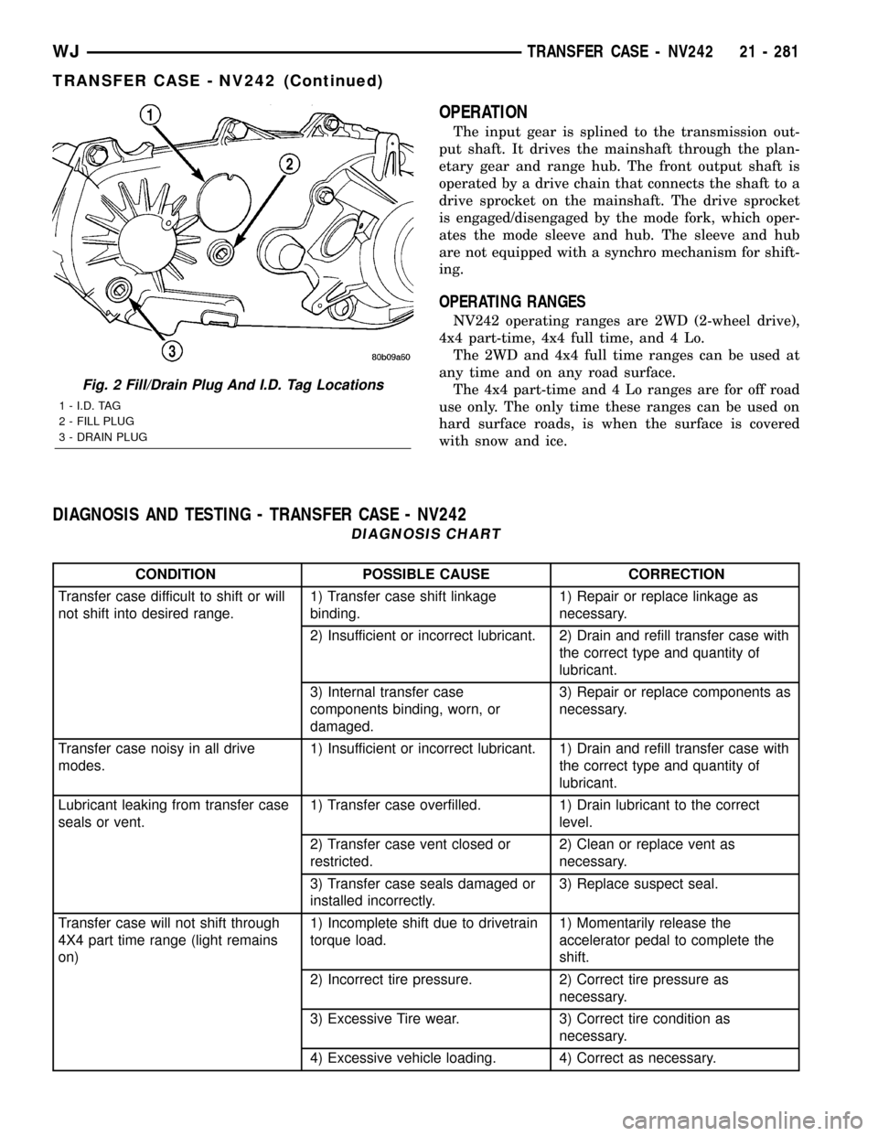
OPERATION
The input gear is splined to the transmission out-
put shaft. It drives the mainshaft through the plan-
etary gear and range hub. The front output shaft is
operated by a drive chain that connects the shaft to a
drive sprocket on the mainshaft. The drive sprocket
is engaged/disengaged by the mode fork, which oper-
ates the mode sleeve and hub. The sleeve and hub
are not equipped with a synchro mechanism for shift-
ing.
OPERATING RANGES
NV242 operating ranges are 2WD (2-wheel drive),
4x4 part-time, 4x4 full time, and 4 Lo.
The 2WD and 4x4 full time ranges can be used at
any time and on any road surface.
The 4x4 part-time and 4 Lo ranges are for off road
use only. The only time these ranges can be used on
hard surface roads, is when the surface is covered
with snow and ice.
DIAGNOSIS AND TESTING - TRANSFER CASE - NV242
DIAGNOSIS CHART
CONDITION POSSIBLE CAUSE CORRECTION
Transfer case difficult to shift or will
not shift into desired range.1) Transfer case shift linkage
binding.1) Repair or replace linkage as
necessary.
2) Insufficient or incorrect lubricant. 2) Drain and refill transfer case with
the correct type and quantity of
lubricant.
3) Internal transfer case
components binding, worn, or
damaged.3) Repair or replace components as
necessary.
Transfer case noisy in all drive
modes.1) Insufficient or incorrect lubricant. 1) Drain and refill transfer case with
the correct type and quantity of
lubricant.
Lubricant leaking from transfer case
seals or vent.1) Transfer case overfilled. 1) Drain lubricant to the correct
level.
2) Transfer case vent closed or
restricted.2) Clean or replace vent as
necessary.
3) Transfer case seals damaged or
installed incorrectly.3) Replace suspect seal.
Transfer case will not shift through
4X4 part time range (light remains
on)1) Incomplete shift due to drivetrain
torque load.1) Momentarily release the
accelerator pedal to complete the
shift.
2) Incorrect tire pressure. 2) Correct tire pressure as
necessary.
3) Excessive Tire wear. 3) Correct tire condition as
necessary.
4) Excessive vehicle loading. 4) Correct as necessary.
Fig. 2 Fill/Drain Plug And I.D. Tag Locations
1 - I.D. TAG
2 - FILL PLUG
3 - DRAIN PLUG
WJTRANSFER CASE - NV242 21 - 281
TRANSFER CASE - NV242 (Continued)
Page 1836 of 2199
CONDITION POSSIBLE CAUSE CORRECTION
NOISY INÐOR JUMPS OUT OF
4WD LOW RANGE1. Transfer case not completely
engaged in 4WD LOW (possibly
from shift to 4L while rolling)1. Stop vehicle, shift transfer case
to neutral, then shift back to 4WD
LOW
2. Shift linkage loose, binding, or is
misadjusted2. Tighten, lubricate, or repair
linkage as necessary. Adjust linkage
if necessary
3. Range fork cracked, inserts
worn, or fork is binding on shift rail3. Disassemble unit and repair as
necessary
4. Annulus gear or lockplate worn
or damaged4. Disassemble unit and repair as
necessary
LUBRICANT LEAKING FROM
OUTPUT SHAFT SEALS OR FROM
VENT1. Transfer case over filled 1. Drain to correct level
2. Vent closed or restricted 2. Clear or replace vent if necessary
3. Output shaft seals damaged or
installed correctly3. Replace seals. Be sure seal lip
faces interior of case when installed.
Also be sure yoke seal surfaces are
not scored or nicked. Remove
scores and nicks with fine
sandpaper or replace yoke(s) if
necessary.
REMOVAL
(1) Shift transfer case into NEUTRAL.
(2) Raise vehicle.
(3) Remove transfer case drain plug and drain
transfer case lubricant.
(4) Mark front and rear propeller shaft yokes for
alignment reference.
(5) Support transmission with jack stand.
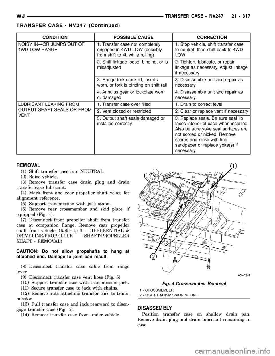
(6) Remove rear crossmember and skid plate, if
equipped (Fig. 4).
(7) Disconnect front propeller shaft from transfer
case at companion flange. Remove rear propeller
shaft from vehicle. (Refer to 3 - DIFFERENTIAL &
DRIVELINE/PROPELLER SHAFT/PROPELLER
SHAFT - REMOVAL)
CAUTION: Do not allow propshafts to hang at
attached end. Damage to joint can result.
(8) Disconnect transfer case cable from range
lever.
(9) Disconnect transfer case vent hose (Fig. 5).
(10) Support transfer case with transmission jack.
(11) Secure transfer case to jack with chains.
(12) Remove nuts attaching transfer case to trans-
mission.
(13) Pull transfer case and jack rearward to disen-
gage transfer case (Fig. 5).
(14) Remove transfer case from under vehicle.
DISASSEMBLY
Position transfer case on shallow drain pan.
Remove drain plug and drain lubricant remaining in
case.
Fig. 4 Crossmember Removal
1 - CROSSMEMBER
2 - REAR TRANSMISSION MOUNT
WJTRANSFER CASE - NV247 21 - 317
TRANSFER CASE - NV247 (Continued)