Linkage JEEP GRAND CHEROKEE 2002 WJ / 2.G User Guide
[x] Cancel search | Manufacturer: JEEP, Model Year: 2002, Model line: GRAND CHEROKEE, Model: JEEP GRAND CHEROKEE 2002 WJ / 2.GPages: 2199, PDF Size: 76.01 MB
Page 623 of 2199
(3) Insert the hook formation on the tip of the
wiper arm through the opening in the wiper blade
superstructure ahead of the wiper blade pivot block/
latch unit far enough to engage the pivot block with
the hook (Fig. 10).
(4) Slide the wiper blade pivot block/latch up into
the hook formation on the tip of the wiper arm until
the latch release tab snaps into its locked position.
Latch engagement will be accompanied by an audible
click.
(5) Gently lower the wiper blade onto the glass.
FRONT WIPER MODULE
DESCRIPTION
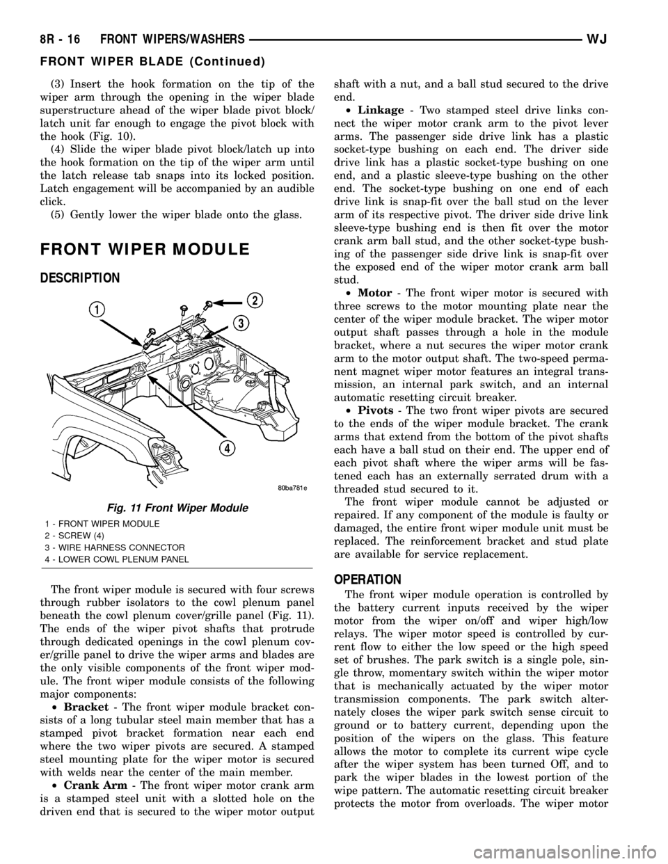
The front wiper module is secured with four screws
through rubber isolators to the cowl plenum panel
beneath the cowl plenum cover/grille panel (Fig. 11).
The ends of the wiper pivot shafts that protrude
through dedicated openings in the cowl plenum cov-
er/grille panel to drive the wiper arms and blades are
the only visible components of the front wiper mod-
ule. The front wiper module consists of the following
major components:
²Bracket- The front wiper module bracket con-
sists of a long tubular steel main member that has a
stamped pivot bracket formation near each end
where the two wiper pivots are secured. A stamped
steel mounting plate for the wiper motor is secured
with welds near the center of the main member.
²Crank Arm- The front wiper motor crank arm
is a stamped steel unit with a slotted hole on the
driven end that is secured to the wiper motor outputshaft with a nut, and a ball stud secured to the drive
end.
²Linkage- Two stamped steel drive links con-
nect the wiper motor crank arm to the pivot lever
arms. The passenger side drive link has a plastic
socket-type bushing on each end. The driver side
drive link has a plastic socket-type bushing on one
end, and a plastic sleeve-type bushing on the other
end. The socket-type bushing on one end of each
drive link is snap-fit over the ball stud on the lever
arm of its respective pivot. The driver side drive link
sleeve-type bushing end is then fit over the motor
crank arm ball stud, and the other socket-type bush-
ing of the passenger side drive link is snap-fit over
the exposed end of the wiper motor crank arm ball
stud.
²Motor- The front wiper motor is secured with
three screws to the motor mounting plate near the
center of the wiper module bracket. The wiper motor
output shaft passes through a hole in the module
bracket, where a nut secures the wiper motor crank
arm to the motor output shaft. The two-speed perma-
nent magnet wiper motor features an integral trans-
mission, an internal park switch, and an internal
automatic resetting circuit breaker.
²Pivots- The two front wiper pivots are secured
to the ends of the wiper module bracket. The crank
arms that extend from the bottom of the pivot shafts
each have a ball stud on their end. The upper end of
each pivot shaft where the wiper arms will be fas-
tened each has an externally serrated drum with a
threaded stud secured to it.
The front wiper module cannot be adjusted or
repaired. If any component of the module is faulty or
damaged, the entire front wiper module unit must be
replaced. The reinforcement bracket and stud plate
are available for service replacement.OPERATION
The front wiper module operation is controlled by
the battery current inputs received by the wiper
motor from the wiper on/off and wiper high/low
relays. The wiper motor speed is controlled by cur-
rent flow to either the low speed or the high speed
set of brushes. The park switch is a single pole, sin-
gle throw, momentary switch within the wiper motor
that is mechanically actuated by the wiper motor
transmission components. The park switch alter-
nately closes the wiper park switch sense circuit to
ground or to battery current, depending upon the
position of the wipers on the glass. This feature
allows the motor to complete its current wipe cycle
after the wiper system has been turned Off, and to
park the wiper blades in the lowest portion of the
wipe pattern. The automatic resetting circuit breaker
protects the motor from overloads. The wiper motor
Fig. 11 Front Wiper Module
1 - FRONT WIPER MODULE
2 - SCREW (4)
3 - WIRE HARNESS CONNECTOR
4 - LOWER COWL PLENUM PANEL
8R - 16 FRONT WIPERS/WASHERSWJ
FRONT WIPER BLADE (Continued)
Page 624 of 2199
crank arm, the two wiper linkage members, and the
two wiper pivots mechanically convert the rotary out-
put of the wiper motor to the back and forth wiping
motion of the wiper arms and blades on the glass.
REMOVAL
(1) Disconnect and isolate the battery negative
cable.
(2) Remove the front wiper arms from the wiper
pivots. (Refer to 8 - ELECTRICAL/FRONT WIPERS/
WASHERS/FRONT WIPER ARMS - REMOVAL).
(3) Unlatch and open the hood.
(4) Remove the hood to plenum seal from the for-
ward flanges of the cowl grille cover and the plenum
panel.
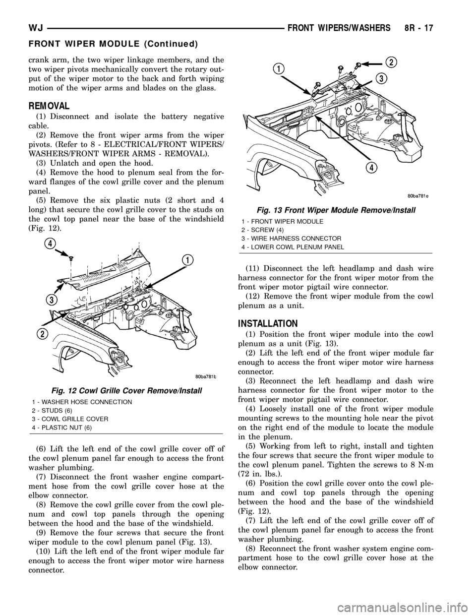
(5) Remove the six plastic nuts (2 short and 4
long) that secure the cowl grille cover to the studs on
the cowl top panel near the base of the windshield
(Fig. 12).
(6) Lift the left end of the cowl grille cover off of
the cowl plenum panel far enough to access the front
washer plumbing.
(7) Disconnect the front washer engine compart-
ment hose from the cowl grille cover hose at the
elbow connector.
(8) Remove the cowl grille cover from the cowl ple-
num and cowl top panels through the opening
between the hood and the base of the windshield.
(9) Remove the four screws that secure the front
wiper module to the cowl plenum panel (Fig. 13).
(10) Lift the left end of the front wiper module far
enough to access the front wiper motor wire harness
connector.(11) Disconnect the left headlamp and dash wire
harness connector for the front wiper motor from the
front wiper motor pigtail wire connector.
(12) Remove the front wiper module from the cowl
plenum as a unit.
INSTALLATION
(1) Position the front wiper module into the cowl
plenum as a unit (Fig. 13).
(2) Lift the left end of the front wiper module far
enough to access the front wiper motor wire harness
connector.
(3) Reconnect the left headlamp and dash wire
harness connector for the front wiper motor to the
front wiper motor pigtail wire connector.
(4) Loosely install one of the front wiper module
mounting screws to the mounting hole near the pivot
on the right end of the module to locate the module
in the plenum.
(5) Working from left to right, install and tighten
the four screws that secure the front wiper module to
the cowl plenum panel. Tighten the screws to 8 N´m
(72 in. lbs.).
(6) Position the cowl grille cover onto the cowl ple-
num and cowl top panels through the opening
between the hood and the base of the windshield
(Fig. 12).
(7) Lift the left end of the cowl grille cover off of
the cowl plenum panel far enough to access the front
washer plumbing.
(8) Reconnect the front washer system engine com-
partment hose to the cowl grille cover hose at the
elbow connector.
Fig. 12 Cowl Grille Cover Remove/Install
1 - WASHER HOSE CONNECTION
2 - STUDS (6)
3 - COWL GRILLE COVER
4 - PLASTIC NUT (6)
Fig. 13 Front Wiper Module Remove/Install
1 - FRONT WIPER MODULE
2 - SCREW (4)
3 - WIRE HARNESS CONNECTOR
4 - LOWER COWL PLENUM PANEL
WJFRONT WIPERS/WASHERS 8R - 17
FRONT WIPER MODULE (Continued)
Page 1265 of 2199

(12) Install the push rods, rocker arms, pivots and
bridges in the order they were removed (Refer to 9 -
ENGINE/CYLINDER HEAD/ROCKER ARM /
ADJUSTER ASSY - INSTALLATION).
(13) Install the engine cylinder head cover (Refer
to 9 - ENGINE/CYLINDER HEAD/CYLINDER
HEAD COVER(S) - INSTALLATION).
(14) Attach the air conditioner compressor mount-
ing bracket to the engine cylinder head and block.
Tighten the bolts to 40 N´m (30 ft. lbs.) torque.
(15) Attach the air conditioning compressor to the
bracket. Tighten the bolts to 27 N´m (20 ft. lbs.)
torque.
CAUTION: The serpentine drive belt must be routed
correctly. Incorrect routing can cause the water
pump to turn in the opposite direction causing the
engine to overheat.
(16) Install the serpentine drive belt. (Refer to 7 -
COOLING/ACCESSORY DRIVE/DRIVE BELTS -
INSTALLATION).
(17) Install the air cleaner and ducting.
(18) Connect the hoses to the engine thermostat
housing and fill the cooling system to the specified
level (Refer to 7 - COOLING - STANDARD PROCE-
DURE).
(19) The automatic transmission throttle linkage
and cable must be adjusted after completing the
engine cylinder head installation (Refer to 21 -
TRANSMISSION/TRANSAXLE/AUTOMATIC - AW4/
THROTTLE VALVE CABLE - ADJUSTMENTS).
(20) Install the temperature sending unit and con-
nect the wire connector.
(21) If equipped with air conditioning, install A/C
compressor (Refer to 24 - HEATING & AIR CONDI-
TIONING/PLUMBING/A/C COMPRESSOR -
INSTALLATION) and charge A/C system (Refer to 24
- HEATING & AIR CONDITIONING/PLUMBING -
STANDARD PROCEDURE).
(22) Connect negative cable to battery.
WARNING: USE EXTREME CAUTION WHEN THE
ENGINE IS OPERATING. DO NOT STAND IN DIRECT
LINE WITH THE FAN. DO NOT PUT HANDS NEAR
THE PULLEYS, BELTS OR FAN. DO NOT WEAR
LOOSE CLOTHING.
(23) Operate the engine with the radiator cap off.
Inspect for leaks and continue operating the engine
until the engine thermostat opens. Add coolant, if
required.CYLINDER HEAD COVER(S)
DESCRIPTION
The cylinder head cover (Fig. 11) is made of
stamped steel and incorporates the Crankcase Venti-
lation (CCV) Hoses and the oil fill opening.
REMOVAL
The cylinder head cover is isolated from the cylin-
der head via grommets and a reusable molded rubber
gasket. The grommet and limiter are retained in the
cylinder head cover.
(1) Disconnect negative cable from battery.
(2) Disconnect the Crankcase Ventilation (CCV)
vacuum hose from engine cylinder head cover.
(3) Disconnect the fresh air inlet hose from the
engine cylinder head cover.
(4) Disconnect the accelerator, transmission, and
speed (if equipped) control cables from the throttle
body (Fig. 12).
(5) Remove the three bolts that fasten the control
cable bracket to the intake manifold.
(6) Remove control cables from cylinder head cover
clip.
(7) Position control cables and bracket away from
cylinder head cover secure with tie straps.
(8) Remove the engine cylinder head cover mount-
ing bolts.
(9) Remove the engine cylinder head cover and
gasket.
Fig. 11 Cylinder Head Cover
9 - 22 ENGINE - 4.0LWJ
CYLINDER HEAD (Continued)
Page 1266 of 2199
CLEANING
Remove any original sealer from the cover sealing
surface of the engine cylinder head and clean the
surface using a fabric cleaner.
Remove all residue from the sealing surface using
a clean, dry cloth.
INSPECTION
Inspect the engine cylinder head cover for cracks.
Replace the cover, if cracked.
The original dark grey gasket material should
NOT be removed. If sections of the gasket material
are missing or are compressed, replace the engine
cylinder head cover. However, sections with minor
damage such as small cracks, cuts or chips may be
repaired with a hand held applicator. The new mate-
rial must be smoothed over to maintain gasket
height. Allow the gasket material to cure prior to
engine cylinder head cover installation.
INSTALLATION
The cylinder head cover is isolated from the cylin-
der head via grommets and a reusable molded rubber
gasket. The grommet and limiter are retained in the
cylinder head cover.
(1) If a replacement cover is installed, transfer the
CCV valve grommet and oil filler cap from the origi-
nal cover to the replacement cover.
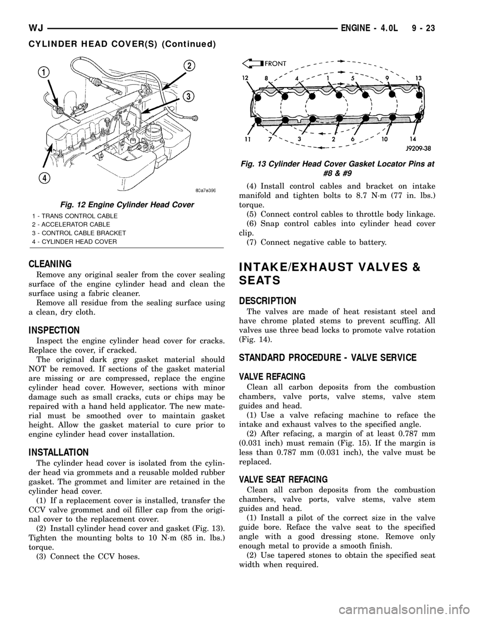
(2) Install cylinder head cover and gasket (Fig. 13).
Tighten the mounting bolts to 10 N´m (85 in. lbs.)
torque.
(3) Connect the CCV hoses.(4) Install control cables and bracket on intake
manifold and tighten bolts to 8.7 N´m (77 in. lbs.)
torque.
(5) Connect control cables to throttle body linkage.
(6) Snap control cables into cylinder head cover
clip.
(7) Connect negative cable to battery.
INTAKE/EXHAUST VALVES &
SEATS
DESCRIPTION
The valves are made of heat resistant steel and
have chrome plated stems to prevent scuffing. All
valves use three bead locks to promote valve rotation
(Fig. 14).
STANDARD PROCEDURE - VALVE SERVICE
VALVE REFACING
Clean all carbon deposits from the combustion
chambers, valve ports, valve stems, valve stem
guides and head.
(1) Use a valve refacing machine to reface the
intake and exhaust valves to the specified angle.
(2) After refacing, a margin of at least 0.787 mm
(0.031 inch) must remain (Fig. 15). If the margin is
less than 0.787 mm (0.031 inch), the valve must be
replaced.
VALVE SEAT REFACING
Clean all carbon deposits from the combustion
chambers, valve ports, valve stems, valve stem
guides and head.
(1) Install a pilot of the correct size in the valve
guide bore. Reface the valve seat to the specified
angle with a good dressing stone. Remove only
enough metal to provide a smooth finish.
(2) Use tapered stones to obtain the specified seat
width when required.
Fig. 12 Engine Cylinder Head Cover
1 - TRANS CONTROL CABLE
2 - ACCELERATOR CABLE
3 - CONTROL CABLE BRACKET
4 - CYLINDER HEAD COVER
Fig. 13 Cylinder Head Cover Gasket Locator Pins at
#8
WJENGINE - 4.0L 9 - 23
CYLINDER HEAD COVER(S) (Continued)
Page 1453 of 2199
(8) Inspect system body grounds for loose or dirty
connections. Refer to Group 8, Wiring for ground
locations.
(9) Verify crankcase ventilation (CCV) operation.
Refer to Emission Control System for additional
information.
(10) Inspect all fuel line quick-connect fittings for
damage or leaks.
(11) Verify hose connections to all ports of vacuum
fittings on intake manifold, and for emission system
are tight and not leaking.
(12) Inspect accelerator cable, transmission throt-
tle cable (if equipped) and speed control cable connec-
tions (if equipped). Check their connections to
throttle body linkage for any binding or restrictions.
(13) Verify vacuum booster hose is firmly con-
nected to fitting on intake manifold. Also check con-
nection to brake vacuum booster.(14) Inspect air cleaner inlet and air cleaner ele-
ment for dirt or restrictions.
(15) Inspect radiator grille area, radiator fins and
air conditioning condenser for restrictions.
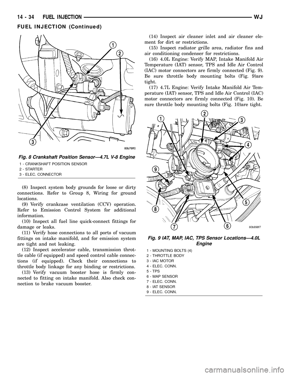
(16) 4.0L Engine: Verify MAP, Intake Manifold Air
Temperature (IAT) sensor, TPS and Idle Air Control
(IAC) motor connectors are firmly connected (Fig. 9).
Be sure throttle body mounting bolts (Fig. 9)are
tight.
(17) 4.7L Engine: Verify Intake Manifold Air Tem-
perature (IAT) sensor, TPS and Idle Air Control (IAC)
motor connectors are firmly connected (Fig. 10). Be
sure throttle body mounting bolts (Fig. 10)are tight.
Fig. 8 Crankshaft Position SensorÐ4.7L V-8 Engine
1 - CRANKSHAFT POSITION SENSOR
2-STARTER
3 - ELEC. CONNECTOR
Fig. 9 IAT, MAP, IAC, TPS Sensor LocationsÐ4.0L
Engine
1 - MOUNTING BOLTS (4)
2 - THROTTLE BODY
3 - IAC MOTOR
4 - ELEC. CONN.
5 - TPS
6 - MAP SENSOR
7 - ELEC. CONN.
8 - IAT SENSOR
9 - ELEC. CONN.
14 - 34 FUEL INJECTIONWJ
FUEL INJECTION (Continued)
Page 1458 of 2199
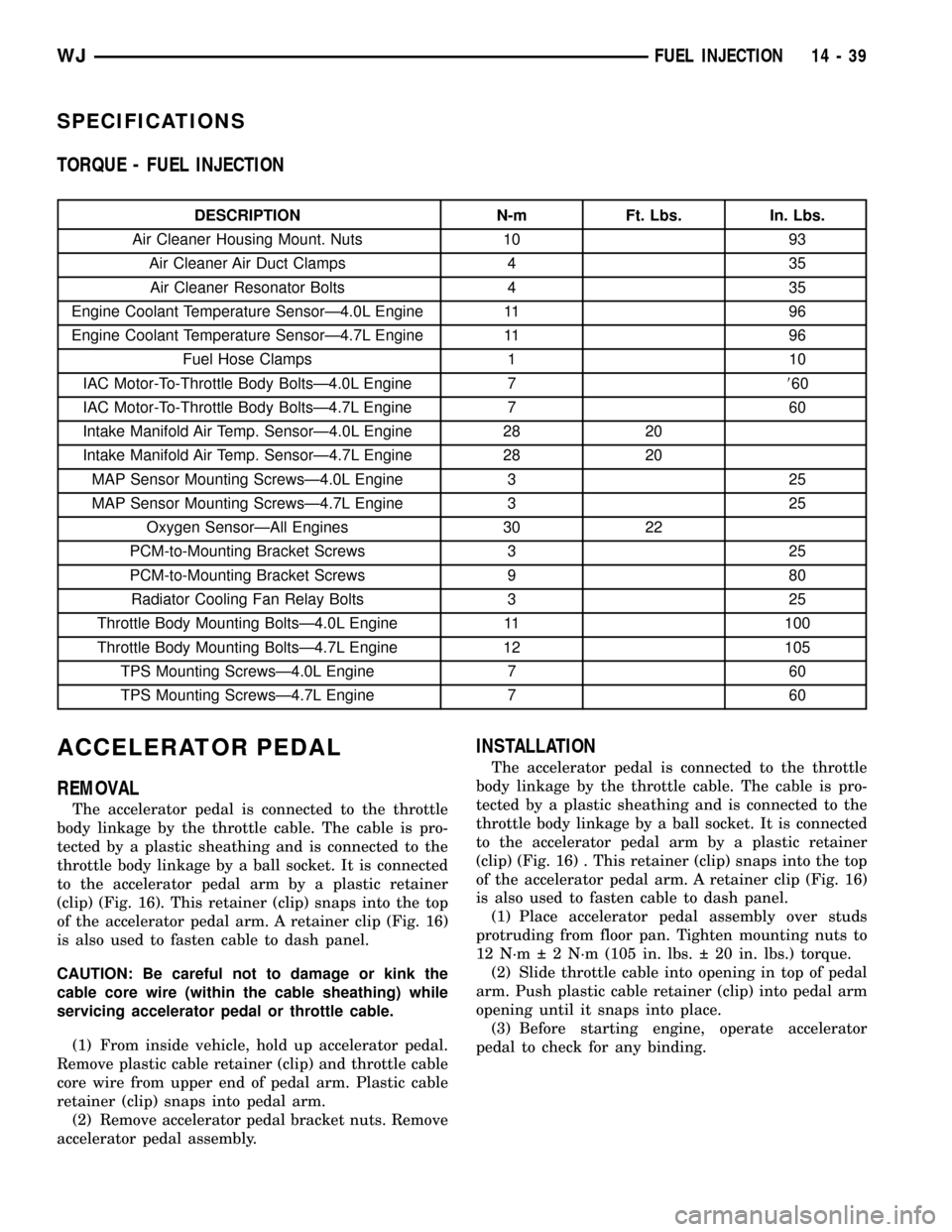
SPECIFICATIONS
TORQUE - FUEL INJECTION
DESCRIPTION N-m Ft. Lbs. In. Lbs.
Air Cleaner Housing Mount. Nuts 10 93
Air Cleaner Air Duct Clamps 4 35
Air Cleaner Resonator Bolts 4 35
Engine Coolant Temperature SensorÐ4.0L Engine 11 96
Engine Coolant Temperature SensorÐ4.7L Engine 11 96
Fuel Hose Clamps 1 10
IAC Motor-To-Throttle Body BoltsÐ4.0L Engine 7860
IAC Motor-To-Throttle Body BoltsÐ4.7L Engine 7 60
Intake Manifold Air Temp. SensorÐ4.0L Engine 28 20
Intake Manifold Air Temp. SensorÐ4.7L Engine 28 20
MAP Sensor Mounting ScrewsÐ4.0L Engine 3 25
MAP Sensor Mounting ScrewsÐ4.7L Engine 3 25
Oxygen SensorÐAll Engines 30 22
PCM-to-Mounting Bracket Screws 3 25
PCM-to-Mounting Bracket Screws 9 80
Radiator Cooling Fan Relay Bolts 3 25
Throttle Body Mounting BoltsÐ4.0L Engine 11 100
Throttle Body Mounting BoltsÐ4.7L Engine 12 105
TPS Mounting ScrewsÐ4.0L Engine 7 60
TPS Mounting ScrewsÐ4.7L Engine 7 60
ACCELERATOR PEDAL
REMOVAL
The accelerator pedal is connected to the throttle
body linkage by the throttle cable. The cable is pro-
tected by a plastic sheathing and is connected to the
throttle body linkage by a ball socket. It is connected
to the accelerator pedal arm by a plastic retainer
(clip) (Fig. 16). This retainer (clip) snaps into the top
of the accelerator pedal arm. A retainer clip (Fig. 16)
is also used to fasten cable to dash panel.
CAUTION: Be careful not to damage or kink the
cable core wire (within the cable sheathing) while
servicing accelerator pedal or throttle cable.
(1) From inside vehicle, hold up accelerator pedal.
Remove plastic cable retainer (clip) and throttle cable
core wire from upper end of pedal arm. Plastic cable
retainer (clip) snaps into pedal arm.
(2) Remove accelerator pedal bracket nuts. Remove
accelerator pedal assembly.
INSTALLATION
The accelerator pedal is connected to the throttle
body linkage by the throttle cable. The cable is pro-
tected by a plastic sheathing and is connected to the
throttle body linkage by a ball socket. It is connected
to the accelerator pedal arm by a plastic retainer
(clip) (Fig. 16) . This retainer (clip) snaps into the top
of the accelerator pedal arm. A retainer clip (Fig. 16)
is also used to fasten cable to dash panel.
(1) Place accelerator pedal assembly over studs
protruding from floor pan. Tighten mounting nuts to
12 N´m 2 N´m (105 in. lbs. 20 in. lbs.) torque.
(2) Slide throttle cable into opening in top of pedal
arm. Push plastic cable retainer (clip) into pedal arm
opening until it snaps into place.
(3) Before starting engine, operate accelerator
pedal to check for any binding.
WJFUEL INJECTION 14 - 39
Page 1471 of 2199

THROTTLE BODY
DESCRIPTION
The throttle body is located on the intake manifold.
Fuel does not enter the intake manifold through the
throttle body. Fuel is sprayed into the manifold by
the fuel injectors.
OPERATION
Filtered air from the air cleaner enters the intake
manifold through the throttle body. The throttle body
contains an air control passage controlled by an Idle
Air Control (IAC) motor. The air control passage is
used to supply air for idle conditions. A throttle valve
(plate) is used to supply air for above idle conditions.
Certain sensors are attached to the throttle body.
The accelerator pedal cable, speed control cable and
transmission control cable (when equipped) are con-
nected to the throttle body linkage arm.A (factory adjusted) set screw is used to mechani-
cally limit the position of the throttle body throttle
plate.Never attempt to adjust the engine idle
speed using this screw.All idle speed functions are
controlled by the PCM.
REMOVAL
REMOVAL - 4.0L
A (factory adjusted) set screw is used to mechani-
cally limit the position of the throttle body throttle
plate.Never attempt to adjust the engine idle
speed using this screw.All idle speed functions are
controlled by the Powertrain Control Module (PCM).
(1) Remove air cleaner duct and air resonator box
at throttle body.
(2) Disconnect throttle body electrical connectors
at MAP sensor, IAC motor and TPS (Fig. 35).
Fig. 33 Oxygen Sensor LocationsÐ4.0L Engine
14 - 52 FUEL INJECTIONWJ
O2S SENSOR (Continued)
Page 1478 of 2199
STEERING
TABLE OF CONTENTS
page page
STEERING
DESCRIPTION - POWER STEERING SYSTEM . . 1
OPERATION - POWER STEERING SYSTEM . . . 1
DIAGNOSIS AND TESTING
DIAGNOSIS AND TESTING - POWER
STEERING SYSTEM....................2
DIAGNOSIS AND TESTING - STEERING
FLOW AND PRESSURE.................4DIAGNOSIS AND TESTING - 4.7L -
HYDRAULIC..........................5
COLUMN...............................7
GEAR.................................16
LINKAGE..............................26
PUMP.................................31
STEERING
DESCRIPTION - POWER STEERING SYSTEM
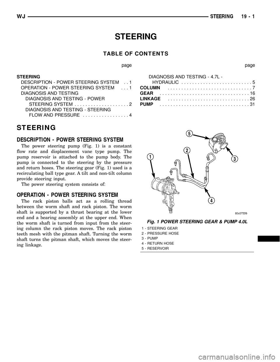
The power steering pump (Fig. 1) is a constant
flow rate and displacement vane type pump. The
pump reservoir is attached to the pump body. The
pump is connected to the steering by the pressure
and return hoses. The steering gear (Fig. 1) used is a
recirculating ball type gear. A tilt and non-tilt column
provide steering input.
The power steering system consists of:
OPERATION - POWER STEERING SYSTEM
The rack piston balls act as a rolling thread
between the worm shaft and rack piston. The worm
shaft is supported by a thrust bearing at the lower
end and a bearing assembly at the upper end. When
the worm shaft is turned from input from the steer-
ing column the rack piston moves. The rack piston
teeth mesh with the pitman shaft. Turning the worm
shaft turns the pitman shaft, which moves the steer-
ing linkage.
Fig. 1 POWER STEERING GEAR & PUMP 4.0L
1 - STEERING GEAR
2 - PRESSURE HOSE
3 - PUMP
4 - RETURN HOSE
5 - RESERVOIR
WJSTEERING 19 - 1
Page 1479 of 2199
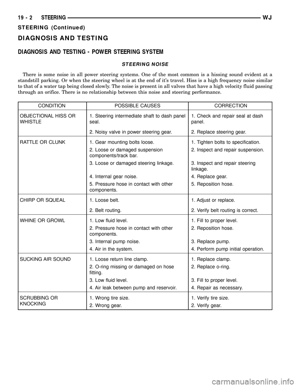
DIAGNOSIS AND TESTING
DIAGNOSIS AND TESTING - POWER STEERING SYSTEM
STEERING NOISE
There is some noise in all power steering systems. One of the most common is a hissing sound evident at a
standstill parking. Or when the steering wheel is at the end of it's travel. Hiss is a high frequency noise similar
to that of a water tap being closed slowly. The noise is present in all valves that have a high velocity fluid passing
through an orifice. There is no relationship between this noise and steering performance.
CONDITION POSSIBLE CAUSES CORRECTION
OBJECTIONAL HISS OR
WHISTLE1. Steering intermediate shaft to dash panel
seal.1. Check and repair seal at dash
panel.
2. Noisy valve in power steering gear. 2. Replace steering gear.
RATTLE OR CLUNK 1. Gear mounting bolts loose. 1. Tighten bolts to specification.
2. Loose or damaged suspension
components/track bar.2. Inspect and repair suspension.
3. Loose or damaged steering linkage. 3. Inspect and repair steering
linkage.
4. Internal gear noise. 4. Replace gear.
5. Pressure hose in contact with other
components.5. Reposition hose.
CHIRP OR SQUEAL 1. Loose belt. 1. Adjust or replace.
2. Belt routing. 2. Verify belt routing is correct.
WHINE OR GROWL 1. Low fluid level. 1. Fill to proper level.
2. Pressure hose in contact with other
components.2. Reposition hose.
3. Internal pump noise. 3. Replace pump.
4. Air in the system. 4. Perform pump initial operation.
SUCKING AIR SOUND 1. Loose return line clamp. 1. Replace clamp.
2. O-ring missing or damaged on hose
fitting.2. Replace o-ring.
3. Low fluid level. 3. Fill to proper level.
4. Air leak between pump and reservoir. 4. Repair as necessary.
SCRUBBING OR
KNOCKING1. Wrong tire size. 1. Verify tire size.
2. Wrong gear. 2. Verify gear.
19 - 2 STEERINGWJ
STEERING (Continued)
Page 1493 of 2199

GEAR
TABLE OF CONTENTS
page page
GEAR
DESCRIPTION.........................16
OPERATION...........................16
REMOVAL.............................16
INSTALLATION.........................16
ADJUSTMENTS
STEERING GEAR.....................18
SPECIFICATIONS
POWER STEERING GEAR..............18
SPECIAL TOOLS
POWER STEERING GEAR..............19
PITMAN SHAFT
REMOVAL.............................20INSTALLATION.........................20
PITMAN SHAFT BEARING
REMOVAL.............................22
INSTALLATION.........................22
PITMAN SHAFT SEAL
REMOVAL.............................22
INSTALLATION.........................23
RACK PISTON/VALVE ASSEMBLY
REMOVAL.............................23
INSTALLATION.........................25
STUB SHAFT HOUSING
REMOVAL.............................25
INSTALLATION.........................25
GEAR
DESCRIPTION
The power steering gear is a recirculating ball type
gear (Fig. 1) .
The following gear components can be serviced:
²Pitman Shaft and Cover
²Pitman Shaft Bearings
²Pitman Shaft Oil Seal/Dust Seal
²Stud Shaft Housing with Seal
²O-Rings and Teflon Rings
NOTE: If rack piston assembly is damaged the gear
must be replaced.
OPERATION
The gear acts as a rolling thread between the
worm shaft and rack piston. The worm shaft is sup-
ported by a thrust bearing at the lower end and a
bearing assembly at the upper end. When the worm
shaft is turned the rack piston moves. The rack pis-
ton teeth mesh with the pitman shaft. Turning the
worm shaft turns the pitman shaft, which turns the
steering linkage.
REMOVAL
(1) Place the front wheels in the straight ahead
position with the steering wheel centered and locked.
(2) Remove the air cleaner housing,(Refer to 9 -
ENGINE/AIR INTAKE SYSTEM/AIR CLEANER
HOUSING - REMOVAL).
(3) Drain or siphon the power steering system.(4) Remove the pressure and return lines (Fig.
2)from the steering gear. Refer to hose removal in
this section.
(5) Remove the column coupler shaft bolt (Fig.
2)and remove the shaft from the gear.
(6) Raise and support the vehicle.
(7) Remove the left front wheel and tire assembly.
(8) Remove the pitman arm from gear with Puller
C-4150A.
(9) Remove the windshield washer reservoir,(Refer
to 8 - ELECTRICAL/WIPERS/WASHERS/WASHER
RESERVOIR - REMOVAL).
(10) Remove the steering gear mounting bolts.
Remove the steering gear out of the engine compart-
ment (Fig. 3).
INSTALLATION
(1) Position the steering gear on the frame rail and
install the bolts. Tighten the bolts to 108 N´m (80 ft.
lbs.) torque.
(2) Install the pitman arm and tighten nut to 251
N´m (185 ft. lbs.).
(3) Install windshield washer reservoir,(Refer to 8 -
ELECTRICAL/WIPERS/WASHERS/WASHER RES-
ERVOIR - INSTALLATION).
(4) Install the wheel and tire assembly.
(5) Remove the support and lower the vehicle.
(6) Install the pressure and return hoses to the
steering gear and tighten to 20-38 N´m (14-28 ft.
lbs.).
(7) Install the column coupler shaft.
(8) Install the air cleaner housing,(Refer to 9 -
ENGINE/AIR INTAKE SYSTEM/AIR CLEANER
HOUSING - INSTALLATION).
19 - 16 GEARWJ