Oil JEEP GRAND CHEROKEE 2002 WJ / 2.G Owner's Guide
[x] Cancel search | Manufacturer: JEEP, Model Year: 2002, Model line: GRAND CHEROKEE, Model: JEEP GRAND CHEROKEE 2002 WJ / 2.GPages: 2199, PDF Size: 76.01 MB
Page 102 of 2199
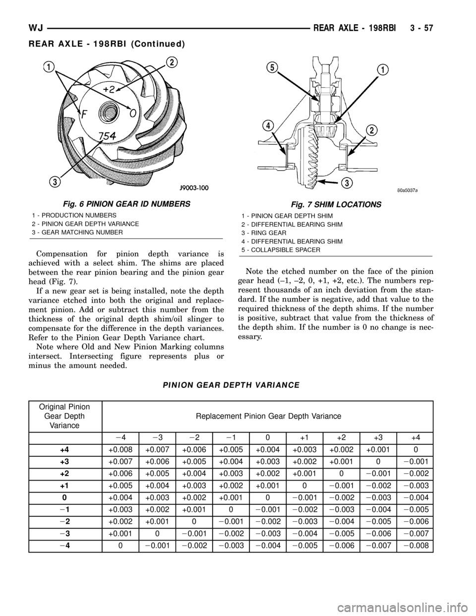
Compensation for pinion depth variance is
achieved with a select shim. The shims are placed
between the rear pinion bearing and the pinion gear
head (Fig. 7).
If a new gear set is being installed, note the depth
variance etched into both the original and replace-
ment pinion. Add or subtract this number from the
thickness of the original depth shim/oil slinger to
compensate for the difference in the depth variances.
Refer to the Pinion Gear Depth Variance chart.
Note where Old and New Pinion Marking columns
intersect. Intersecting figure represents plus or
minus the amount needed.Note the etched number on the face of the pinion
gear head (±1, ±2, 0, +1, +2, etc.). The numbers rep-
resent thousands of an inch deviation from the stan-
dard. If the number is negative, add that value to the
required thickness of the depth shims. If the number
is positive, subtract that value from the thickness of
the depth shim. If the number is 0 no change is nec-
essary.
PINION GEAR DEPTH VARIANCE
Original Pinion
Gear Depth
VarianceReplacement Pinion Gear Depth Variance
24232221 0 +1 +2 +3 +4
+4+0.008 +0.007 +0.006 +0.005 +0.004 +0.003 +0.002 +0.001 0
+3+0.007 +0.006 +0.005 +0.004 +0.003 +0.002 +0.001 020.001
+2+0.006 +0.005 +0.004 +0.003 +0.002 +0.001 020.00120.002
+1+0.005 +0.004 +0.003 +0.002 +0.001 020.00120.00220.003
0+0.004 +0.003 +0.002 +0.001 020.00120.00220.00320.004
21+0.003 +0.002 +0.001 020.00120.00220.00320.00420.005
22+0.002 +0.001 020.00120.00220.00320.00420.00520.006
23+0.001 020.00120.00220.00320.00420.00520.00620.007
24020.00120.00220.00320.00420.00520.00620.00720.008
Fig. 6 PINION GEAR ID NUMBERS
1 - PRODUCTION NUMBERS
2 - PINION GEAR DEPTH VARIANCE
3 - GEAR MATCHING NUMBER
Fig. 7 SHIM LOCATIONS
1 - PINION GEAR DEPTH SHIM
2 - DIFFERENTIAL BEARING SHIM
3 - RING GEAR
4 - DIFFERENTIAL BEARING SHIM
5 - COLLAPSIBLE SPACER
WJREAR AXLE - 198RBI 3 - 57
REAR AXLE - 198RBI (Continued)
Page 120 of 2199
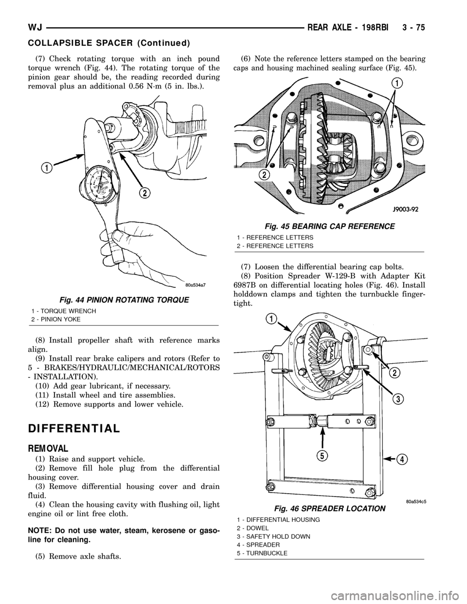
(7) Check rotating torque with an inch pound
torque wrench (Fig. 44). The rotating torque of the
pinion gear should be, the reading recorded during
removal plus an additional 0.56 N´m (5 in. lbs.).
(8) Install propeller shaft with reference marks
align.
(9) Install rear brake calipers and rotors (Refer to
5 - BRAKES/HYDRAULIC/MECHANICAL/ROTORS
- INSTALLATION).
(10) Add gear lubricant, if necessary.
(11) Install wheel and tire assemblies.
(12) Remove supports and lower vehicle.
DIFFERENTIAL
REMOVAL
(1) Raise and support vehicle.
(2) Remove fill hole plug from the differential
housing cover.
(3) Remove differential housing cover and drain
fluid.
(4) Clean the housing cavity with flushing oil, light
engine oil or lint free cloth.
NOTE: Do not use water, steam, kerosene or gaso-
line for cleaning.
(5) Remove axle shafts.(6)
Note the reference letters stamped on the bearing
caps and housing machined sealing surface (Fig. 45).
(7) Loosen the differential bearing cap bolts.
(8) Position Spreader W-129-B with Adapter Kit
6987B on differential locating holes (Fig. 46). Install
holddown clamps and tighten the turnbuckle finger-
tight.
Fig. 44 PINION ROTATING TORQUE
1 - TORQUE WRENCH
2 - PINION YOKE
Fig. 45 BEARING CAP REFERENCE
1 - REFERENCE LETTERS
2 - REFERENCE LETTERS
Fig. 46 SPREADER LOCATION
1 - DIFFERENTIAL HOUSING
2 - DOWEL
3 - SAFETY HOLD DOWN
4 - SPREADER
5 - TURNBUCKLE
WJREAR AXLE - 198RBI 3 - 75
COLLAPSIBLE SPACER (Continued)
Page 122 of 2199
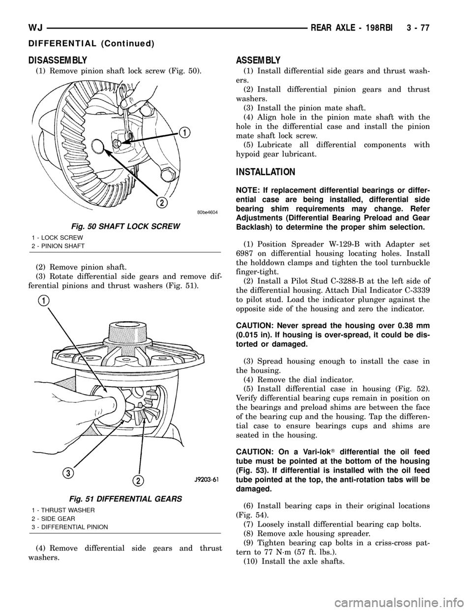
DISASSEMBLY
(1) Remove pinion shaft lock screw (Fig. 50).
(2) Remove pinion shaft.
(3) Rotate differential side gears and remove dif-
ferential pinions and thrust washers (Fig. 51).
(4) Remove differential side gears and thrust
washers.
ASSEMBLY
(1) Install differential side gears and thrust wash-
ers.
(2) Install differential pinion gears and thrust
washers.
(3) Install the pinion mate shaft.
(4) Align hole in the pinion mate shaft with the
hole in the differential case and install the pinion
mate shaft lock screw.
(5) Lubricate all differential components with
hypoid gear lubricant.
INSTALLATION
NOTE: If replacement differential bearings or differ-
ential case are being installed, differential side
bearing shim requirements may change. Refer
Adjustments (Differential Bearing Preload and Gear
Backlash) to determine the proper shim selection.
(1) Position Spreader W-129-B with Adapter set
6987 on differential housing locating holes. Install
the holddown clamps and tighten the tool turnbuckle
finger-tight.
(2) Install a Pilot Stud C-3288-B at the left side of
the differential housing. Attach Dial Indicator C-3339
to pilot stud. Load the indicator plunger against the
opposite side of the housing and zero the indicator.
CAUTION: Never spread the housing over 0.38 mm
(0.015 in). If housing is over-spread, it could be dis-
torted or damaged.
(3) Spread housing enough to install the case in
the housing.
(4) Remove the dial indicator.
(5) Install differential case in housing (Fig. 52).
Verify differential bearing cups remain in position on
the bearings and preload shims are between the face
of the bearing cup and the housing. Tap the differen-
tial case to ensure bearings cups and shims are
seated in the housing.
CAUTION: On a Vari-lokTdifferential the oil feed
tube must be pointed at the bottom of the housing
(Fig. 53). If differential is installed with the oil feed
tube pointed at the top, the anti-rotation tabs will be
damaged.
(6) Install bearing caps in their original locations
(Fig. 54).
(7) Loosely install differential bearing cap bolts.
(8) Remove axle housing spreader.
(9) Tighten bearing cap bolts in a criss-cross pat-
tern to 77 N´m (57 ft. lbs.).
(10) Install the axle shafts.
Fig. 50 SHAFT LOCK SCREW
1 - LOCK SCREW
2 - PINION SHAFT
Fig. 51 DIFFERENTIAL GEARS
1 - THRUST WASHER
2 - SIDE GEAR
3 - DIFFERENTIAL PINION
WJREAR AXLE - 198RBI 3 - 77
DIFFERENTIAL (Continued)
Page 123 of 2199
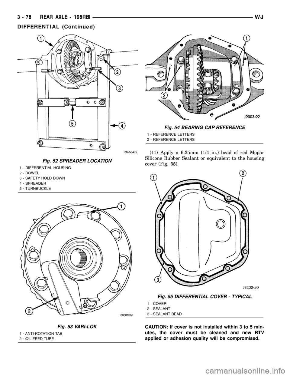
(11) Apply a 6.35mm (1/4 in.) bead of red Mopar
Silicone Rubber Sealant or equivalent to the housing
cover (Fig. 55).
CAUTION: If cover is not installed within 3 to 5 min-
utes, the cover must be cleaned and new RTV
applied or adhesion quality will be compromised.
Fig. 52 SPREADER LOCATION
1 - DIFFERENTIAL HOUSING
2 - DOWEL
3 - SAFETY HOLD DOWN
4 - SPREADER
5 - TURNBUCKLE
Fig. 53 VARI-LOK
1 - ANTI-ROTATION TAB
2 - OIL FEED TUBE
Fig. 54 BEARING CAP REFERENCE
1 - REFERENCE LETTERS
2 - REFERENCE LETTERS
Fig. 55 DIFFERENTIAL COVER - TYPICAL
1 - COVER
2 - SEALANT
3 - SEALANT BEAD
3 - 78 REAR AXLE - 198RBIWJ
DIFFERENTIAL (Continued)
Page 130 of 2199
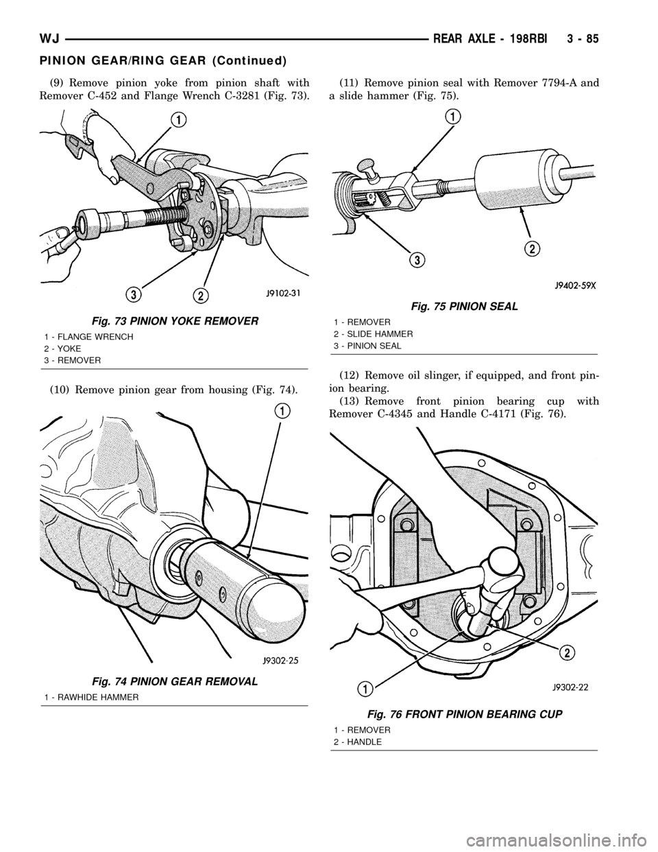
(9) Remove pinion yoke from pinion shaft with
Remover C-452 and Flange Wrench C-3281 (Fig. 73).
(10) Remove pinion gear from housing (Fig. 74).(11) Remove pinion seal with Remover 7794-A and
a slide hammer (Fig. 75).
(12) Remove oil slinger, if equipped, and front pin-
ion bearing.
(13) Remove front pinion bearing cup with
Remover C-4345 and Handle C-4171 (Fig. 76).
Fig. 73 PINION YOKE REMOVER
1 - FLANGE WRENCH
2 - YOKE
3 - REMOVER
Fig. 74 PINION GEAR REMOVAL
1 - RAWHIDE HAMMER
Fig. 75 PINION SEAL
1 - REMOVER
2 - SLIDE HAMMER
3 - PINION SEAL
Fig. 76 FRONT PINION BEARING CUP
1 - REMOVER
2 - HANDLE
WJREAR AXLE - 198RBI 3 - 85
PINION GEAR/RING GEAR (Continued)
Page 131 of 2199
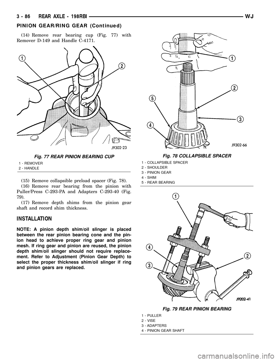
(14) Remove rear bearing cup (Fig. 77) with
Remover D-149 and Handle C-4171.
(15) Remove collapsible preload spacer (Fig. 78).
(16) Remove rear bearing from the pinion with
Puller/Press C-293-PA and Adapters C-293-40 (Fig.
79).
(17) Remove depth shims from the pinion gear
shaft and record shim thickness.
INSTALLATION
NOTE: A pinion depth shim/oil slinger is placed
between the rear pinion bearing cone and the pin-
ion head to achieve proper ring gear and pinion
mesh. If ring gear and pinion are reused, the pinion
depth shim/oil slinger should not require replace-
ment. Refer to Adjustment (Pinion Gear Depth) to
select the proper thickness shim/oil slinger if ring
and pinion gears are replaced.
Fig. 77 REAR PINION BEARING CUP
1 - REMOVER
2 - HANDLE
Fig. 78 COLLAPSIBLE SPACER
1 - COLLAPSIBLE SPACER
2 - SHOULDER
3 - PINION GEAR
4 - SHIM
5 - REAR BEARING
Fig. 79 REAR PINION BEARING
1 - PULLER
2 - VISE
3 - ADAPTERS
4 - PINION GEAR SHAFT
3 - 86 REAR AXLE - 198RBIWJ
PINION GEAR/RING GEAR (Continued)
Page 132 of 2199
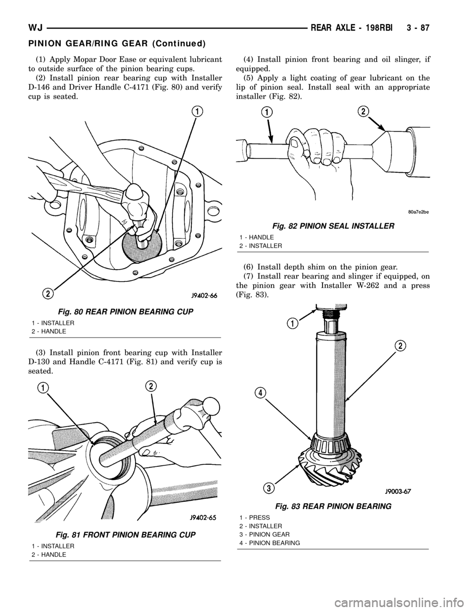
(1) Apply Mopar Door Ease or equivalent lubricant
to outside surface of the pinion bearing cups.
(2) Install pinion rear bearing cup with Installer
D-146 and Driver Handle C-4171 (Fig. 80) and verify
cup is seated.
(3) Install pinion front bearing cup with Installer
D-130 and Handle C-4171 (Fig. 81) and verify cup is
seated.(4) Install pinion front bearing and oil slinger, if
equipped.
(5) Apply a light coating of gear lubricant on the
lip of pinion seal. Install seal with an appropriate
installer (Fig. 82).
(6) Install depth shim on the pinion gear.
(7) Install rear bearing and slinger if equipped, on
the pinion gear with Installer W-262 and a press
(Fig. 83).
Fig. 80 REAR PINION BEARING CUP
1 - INSTALLER
2 - HANDLE
Fig. 81 FRONT PINION BEARING CUP
1 - INSTALLER
2 - HANDLE
Fig. 82 PINION SEAL INSTALLER
1 - HANDLE
2 - INSTALLER
Fig. 83 REAR PINION BEARING
1 - PRESS
2 - INSTALLER
3 - PINION GEAR
4 - PINION BEARING
WJREAR AXLE - 198RBI 3 - 87
PINION GEAR/RING GEAR (Continued)
Page 134 of 2199
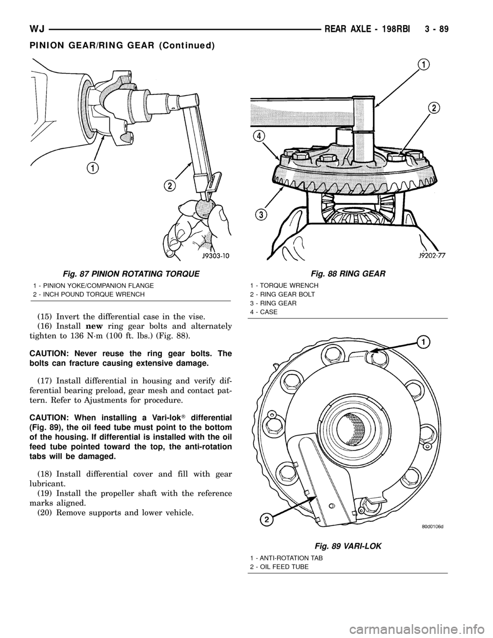
(15) Invert the differential case in the vise.
(16) Installnewring gear bolts and alternately
tighten to 136 N´m (100 ft. lbs.) (Fig. 88).
CAUTION: Never reuse the ring gear bolts. The
bolts can fracture causing extensive damage.
(17) Install differential in housing and verify dif-
ferential bearing preload, gear mesh and contact pat-
tern. Refer to Ajustments for procedure.
CAUTION: When installing a Vari-lokTdifferential
(Fig. 89), the oil feed tube must point to the bottom
of the housing. If differential is installed with the oil
feed tube pointed toward the top, the anti-rotation
tabs will be damaged.
(18) Install differential cover and fill with gear
lubricant.
(19) Install the propeller shaft with the reference
marks aligned.
(20) Remove supports and lower vehicle.
Fig. 87 PINION ROTATING TORQUE
1 - PINION YOKE/COMPANION FLANGE
2 - INCH POUND TORQUE WRENCH
Fig. 88 RING GEAR
1 - TORQUE WRENCH
2 - RING GEAR BOLT
3 - RING GEAR
4 - CASE
Fig. 89 VARI-LOK
1 - ANTI-ROTATION TAB
2 - OIL FEED TUBE
WJREAR AXLE - 198RBI 3 - 89
PINION GEAR/RING GEAR (Continued)
Page 141 of 2199
(3) Remove the wheels and tires.
(4) Remove brake calipers and rotors.
(5) Disconnect parking brake cables from brackets
and lever.
(6) Remove wheel speed sensors.
(7) Remove brake hose at the axle junction block.
Do not disconnect the brake hydraulic lines at the
calipers.
(8) Disconnect the vent hose from the axle shaft
tube.
(9) Mark propeller shaft and yokes for installation
reference.
(10) Remove propeller shaft.
(11) Disconnect stabilizer bar links.
(12) Remove upper suspension arm rear axle ball
joint nut.
(13) Separate rear axle ball joint from the upper
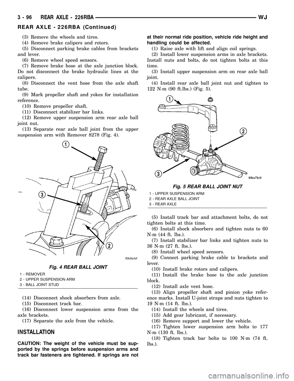
suspension arm with Remover 8278 (Fig. 4).
(14) Disconnect shock absorbers from axle.
(15) Disconnect track bar.
(16) Disconnect lower suspension arms from the
axle brackets.
(17) Separate the axle from the vehicle.
INSTALLATION
CAUTION: The weight of the vehicle must be sup-
ported by the springs before suspension arms and
track bar fasteners are tightened. If springs are notat their normal ride position, vehicle ride height and
handling could be affected.
(1) Raise axle with lift and align coil springs.
(2) Install lower suspension arms in axle brackets.
Install nuts and bolts, do not tighten bolts at this
time.
(3) Install upper suspension arm on rear axle ball
joint.
(4) Install rear axle ball joint nut and tighten to
122 N´m (90 ft.lbs.) (Fig. 5).
(5) Install track bar and attachment bolts, do not
tighten bolts at this time.
(6) Install shock absorbers and tighten nuts to 60
N´m (44 ft. lbs.).
(7) Install stabilizer bar links and tighten nuts to
36 N´m (27 ft. lbs.).
(8) Install wheel speed sensors.
(9) Connect parking brake cable to brackets and
lever.
(10) Install brake rotors and calipers.
(11) Install the brake hose to the axle junction
block.
(12) Install axle vent hose.
(13) Align propeller shaft and pinion yoke refer-
ence marks. Install U-joint straps and nuts tighten to
19 N´m (14 ft. lbs.).
(14) Install the wheels and tires.
(15) Add gear lubricant, if necessary.
(16) Remove support and lower the vehicle.
(17) Tighten lower suspension arm bolts to 177
N´m (130 ft. lbs.).
(18) Tighten track bar bolts to 100 N´m (74 ft.
lbs.).
Fig. 4 REAR BALL JOINT
1 - REMOVER
2 - UPPER SUSPENSION ARM
3 - BALL JOINT STUD
Fig. 5 REAR BALL JOINT NUT
1 - UPPER SUSPENSION ARM
2 - REAR AXLE BALL JOINT
3 - REAR AXLE
3 - 96 REAR AXLE - 226RBAWJ
REAR AXLE - 226RBA (Continued)
Page 142 of 2199
ADJUSTMENTS
Ring and pinion gears are supplied as matched
sets only. The identifying numbers for the ring and
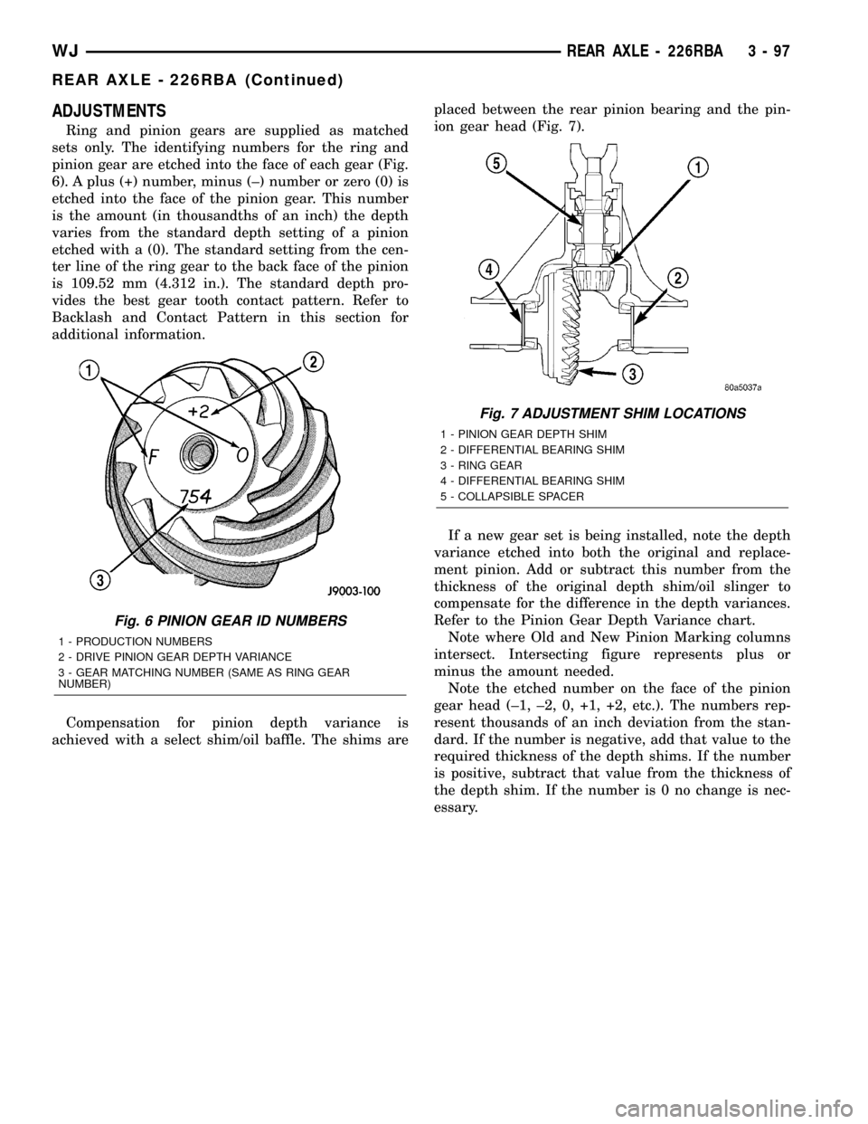
pinion gear are etched into the face of each gear (Fig.
6). A plus (+) number, minus (±) number or zero (0) is
etched into the face of the pinion gear. This number
is the amount (in thousandths of an inch) the depth
varies from the standard depth setting of a pinion
etched with a (0). The standard setting from the cen-
ter line of the ring gear to the back face of the pinion
is 109.52 mm (4.312 in.). The standard depth pro-
vides the best gear tooth contact pattern. Refer to
Backlash and Contact Pattern in this section for
additional information.
Compensation for pinion depth variance is
achieved with a select shim/oil baffle. The shims areplaced between the rear pinion bearing and the pin-
ion gear head (Fig. 7).
If a new gear set is being installed, note the depth
variance etched into both the original and replace-
ment pinion. Add or subtract this number from the
thickness of the original depth shim/oil slinger to
compensate for the difference in the depth variances.
Refer to the Pinion Gear Depth Variance chart.
Note where Old and New Pinion Marking columns
intersect. Intersecting figure represents plus or
minus the amount needed.
Note the etched number on the face of the pinion
gear head (±1, ±2, 0, +1, +2, etc.). The numbers rep-
resent thousands of an inch deviation from the stan-
dard. If the number is negative, add that value to the
required thickness of the depth shims. If the number
is positive, subtract that value from the thickness of
the depth shim. If the number is 0 no change is nec-
essary.
Fig. 6 PINION GEAR ID NUMBERS
1 - PRODUCTION NUMBERS
2 - DRIVE PINION GEAR DEPTH VARIANCE
3 - GEAR MATCHING NUMBER (SAME AS RING GEAR
NUMBER)
Fig. 7 ADJUSTMENT SHIM LOCATIONS
1 - PINION GEAR DEPTH SHIM
2 - DIFFERENTIAL BEARING SHIM
3 - RING GEAR
4 - DIFFERENTIAL BEARING SHIM
5 - COLLAPSIBLE SPACER
WJREAR AXLE - 226RBA 3 - 97
REAR AXLE - 226RBA (Continued)