Specifications JEEP GRAND CHEROKEE 2002 WJ / 2.G Owner's Guide
[x] Cancel search | Manufacturer: JEEP, Model Year: 2002, Model line: GRAND CHEROKEE, Model: JEEP GRAND CHEROKEE 2002 WJ / 2.GPages: 2199, PDF Size: 76.01 MB
Page 217 of 2199
DIAGNOSIS AND TESTING - ANTILOCK
BRAKES
The ABS brake system performs several self-tests
every time the ignition switch is turned on and the
vehicle is driven. The CAB monitors the systems
input and output circuits to verify the system is oper-
ating correctly. If the on board diagnostic system
senses that a circuit is malfunctioning the system
will set a trouble code in its memory.
NOTE: An audible noise may be heard during the
self-test. This noise should be considered normal.
NOTE: The MDS or DRB III scan tool is used to
diagnose the ABS system. For additional informa-
tion refer to the Electrical section. For test proce-
dures refer to the Chassis Diagnostic Manual.
STANDARD PROCEDURE - BLEEDING ABS
BRAKE SYSTEM
ABS system bleeding requires conventional bleed-
ing methods plus use of the DRB scan tool. The pro-cedure involves performing a base brake bleeding,
followed by use of the scan tool to cycle and bleed the
HCU pump and solenoids. A second base brake bleed-
ing procedure is then required to remove any air
remaining in the system.
(1) Perform base brake bleeding. (Refer to 5 -
BRAKES - STANDARD PROCEDURE) OR (Refer to
5 - BRAKES - STANDARD PROCEDURE).
(2) Connect scan tool to the Data Link Connector.
(3) Select ANTILOCK BRAKES, followed by MIS-
CELLANEOUS, then ABS BRAKES. Follow the
instructions displayed. When scan tool displays TEST
COMPLETE, disconnect scan tool and proceed.
(4) Perform base brake bleeding a second time.
(Refer to 5 - BRAKES - STANDARD PROCEDURE)
OR (Refer to 5 - BRAKES - STANDARD PROCE-
DURE).
(5) Top off master cylinder fluid level and verify
proper brake operation before moving vehicle.
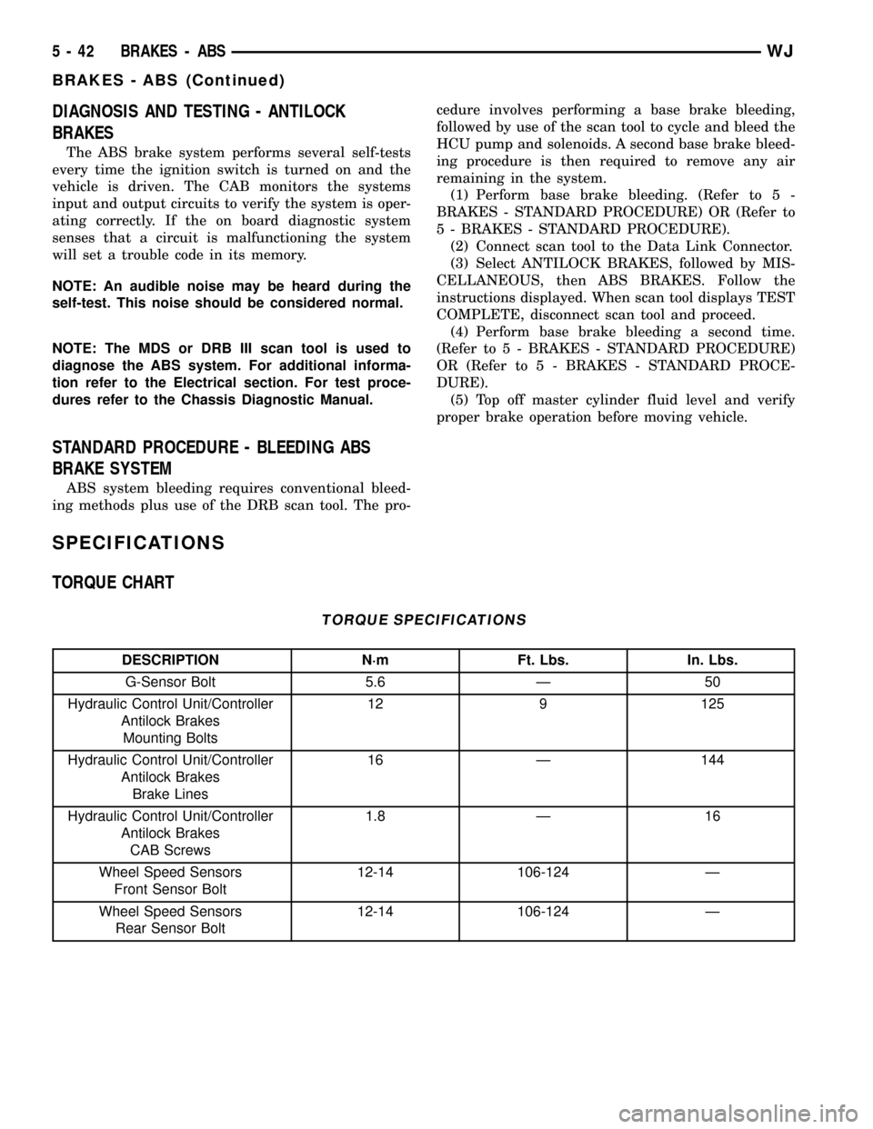
SPECIFICATIONS
TORQUE CHART
TORQUE SPECIFICATIONS
DESCRIPTION N´m Ft. Lbs. In. Lbs.
G-Sensor Bolt 5.6 Ð 50
Hydraulic Control Unit/Controller
Antilock Brakes
Mounting Bolts12 9 125
Hydraulic Control Unit/Controller
Antilock Brakes
Brake Lines16 Ð 144
Hydraulic Control Unit/Controller
Antilock Brakes
CAB Screws1.8 Ð 16
Wheel Speed Sensors
Front Sensor Bolt12-14 106-124 Ð
Wheel Speed Sensors
Rear Sensor Bolt12-14 106-124 Ð
5 - 42 BRAKES - ABSWJ
BRAKES - ABS (Continued)
Page 224 of 2199

COOLING
TABLE OF CONTENTS
page page
COOLING
DESCRIPTION
DESCRIPTION - COOLING SYSTEM 4.7L
ENGINE..............................1
DESCRIPTION - COOLING SYSTEM
ROUTING 4.7L ENGINE..................1
DESCRIPTIONÐCOOLING SYSTEM 4.0L
ENGINE..............................1
DESCRIPTIONÐCOOLING SYSTEM
ROUTING 4.0L ENGINE..................1
DESCRIPTIONÐHOSE CLAMPS...........1
OPERATION
OPERATIONÐCOOLING SYSTEM.........2
OPERATIONÐHOSE CLAMPS............2
DIAGNOSIS AND TESTING
DIAGNOSIS AND TESTINGÐON-BOARD
DIAGNOSTICS (OBD)...................3
DIAGNOSIS AND TESTINGÐPRELIMINARY
CHECKS.............................3
DIAGNOSIS AND TESTING - COOLING
SYSTEM DIAGNOSIS CHART.............5
DIAGNOSIS AND TESTING - COOLING
SYSTEM LEAKS......................10DIAGNOSIS AND TESTING - COOLING
SYSTEM DEAERATION.................12
STANDARD PROCEDURE
STANDARD PROCEDUREÐDRAINING
COOLING SYSTEM 4.7L ENGINE.........12
STANDARD PROCEDURE - REFILLING
COOLING SYSTEM 4.7L ENGINE.........12
STANDARD PROCEDURE - DRAINING
COOLING SYSTEM - 4.0L ENGINE........13
STANDARD PROCEDURE - REFILLING
COOLING SYSTEM - 4.0L ENGINE........13
STANDARD PROCEDURE - ADDING
ADDITIONAL COOLANT.................13
STANDARD PROCEDURE - COOLING
SYSTEM - REVERSE FLUSHING..........14
SPECIFICATIONS
TORQUE............................14
SPECIAL TOOLS
COOLING...........................15
ACCESSORY DRIVE......................16
ENGINE...............................24
TRANSMISSION.........................55
COOLING
DESCRIPTION
DESCRIPTION - COOLING SYSTEM 4.7L
ENGINE
The cooling system consists of the following items:
²Hydraulic cooling fan and fan drive assembly
²Radiator
²Power steering oil cooler
²Radiator pressure cap
²Thermostat
²Coolant reserve/overflow system
²Transmission oil cooler (if equipped with an
automatic transmission)
²Coolant
²Water pump
²Hoses and hose clamps
DESCRIPTION - COOLING SYSTEM ROUTING
4.7L ENGINE
For cooling system routing refer to (Fig. 1).
DESCRIPTIONÐCOOLING SYSTEM 4.0L
ENGINE
The cooling system consists of:
²A radiator
²Mechanical Cooling Fan
²Thermal viscous fan drive-Low disengaged
²Fan shroud (Fig. 2)
²Radiator pressure cap
²Thermostat
²Coolant reserve/overflow system
²Transmission oil cooler (if equipped with an
automatic transmission)
²Coolant
²Water pump
²Hoses and hose clamps
²Accessory drive belt
DESCRIPTIONÐCOOLING SYSTEM ROUTING
4.0L ENGINE
For cooling system routing refer to (Fig. 3).
DESCRIPTIONÐHOSE CLAMPS
The cooling system utilizes both worm drive and
spring type hose clamps. If a spring type clamp
WJCOOLING 7 - 1
Page 227 of 2199

²SLIGHT TAIL WIND AT IDLE
²SLOW TRAFFIC
²TRAFFIC JAMS
²HIGH SPEED
²STEEP GRADES
Driving techniques that avoid overheating are:
²Idle with A/C off when temperature gauge is at
end of normal range.
²Increase engine speed for more air flow is recom-
mended.(1) TRAILER TOWING:
Consult Trailer Towing section of owners manual.
Do not exceed limits.
(2) AIR CONDITIONING; ADD-ON OR AFTER
MARKET:
A maximum cooling package should have been
ordered with vehicle if add-on or after market A/C is
installed. If not, maximum cooling system compo-
nents should be installed for model involved per
manufacturer's specifications.
(3) RECENT SERVICE OR ACCIDENT REPAIR:
Determine if any recent service has been per-
formed on vehicle that may effect cooling system.
This may be:
²Engine adjustments (incorrect timing)
²Slipping engine accessory drive belt(s)
²Brakes (possibly dragging)
²Changed parts. Incorrect water pump, or pump
rotating in wrong direction due to belt not correctly
routed
²Reconditioned radiator or cooling system refill-
ing (possibly under filled or air trapped in system).
NOTE: If investigation reveals none of the previous
items as a cause for an engine overheating com-
plaint, refer to following Cooling System Diagnosis
charts.
These charts are to be used as a quick-reference
only. Refer to the group text for information.
Fig. 4 Spring Clamp Size Location
1 - SPRING CLAMP SIZE LOCATION
7 - 4 COOLINGWJ
COOLING (Continued)
Page 237 of 2199
corrosion inhibitors called HOAT, for Hybrid Organic
Additive Technology) is recommended. This coolant
offers the best engine cooling without corrosion when
mixed with 50% distilled water to obtain to obtain a
freeze point of -37ÉC (-35ÉF). If it loses color or
becomes contaminated, drain, flush, and replace with
fresh properly mixed coolant solution.
CAUTION: Do not use coolant additives that are
claimed to improve engine cooling.
STANDARD PROCEDURE - COOLING SYSTEM -
REVERSE FLUSHING
CAUTION: The cooling system normally operates at
97-to-124 kPa (14-to -18 psi) pressure. Exceeding
this pressure may damage the radiator or hoses.
Reverse flushing of the cooling system is the forc-
ing of water through the cooling system. This is done
using air pressure in the opposite direction of normal
coolant flow. It is usually only necessary with very
dirty systems with evidence of partial plugging.
CHEMICAL CLEANING
If visual inspection indicates the formation of
sludge or scaly deposits, use a radiator cleaner
(Mopar Radiator Kleen or equivalent) before flushing.
This will soften scale and other deposits and aid the
flushing operation.
CAUTION: Be sure instructions on the container are
followed.
REVERSE FLUSHING RADIATOR
Disconnect the radiator hoses from the radiator fit-
tings. Attach a section of radiator hose to the radia-
tor bottom outlet fitting and insert the flushing gun.
Connect a water supply hose and air supply hose to
the flushing gun.
CAUTION: The cooling system normally operates at
97-to-124 kPa (14- to-18 psi) pressure. Exceeding
this pressure may damage the radiator or hoses.
Allow the radiator to fill with water. When radiator
is filled, apply air in short blasts allowing radiator to
refill between blasts. Continue this reverse flushing
until clean water flows out through rear of radiator
cooling tube passages. For more information, refer to
operating instructions supplied with flushing equip-
ment. Have radiator cleaned more extensively by a
radiator repair shop.
REVERSE FLUSHING ENGINE
Drain the cooling system (Refer to 7 - COOLING -
STANDARD PROCEDURE). Remove the thermostat
housing and thermostat. Install the thermostat hous-
ing. Disconnect the radiator upper hose from the
radiator and attach the flushing gun to the hose. Dis-
connect the radiator lower hose from the water
pump. Attach a lead away hose to the water pump
inlet fitting.
CAUTION: Be sure that the heater control valve is
closed (heat off). This is done to prevent coolant
flow with scale and other deposits from entering
the heater core.
Connect the water supply hose and air supply hose
to the flushing gun. Allow the engine to fill with
water. When the engine is filled, apply air in short
blasts, allowing the system to fill between air blasts.
Continue until clean water flows through the lead
away hose. For more information, refer to operating
instructions supplied with flushing equipment.
Remove the lead away hose, flushing gun, water
supply hose and air supply hose. Remove the thermo-
stat housing (Refer to 7 - COOLING/ENGINE/EN-
GINE COOLANT THERMOSTAT - REMOVAL).
Install the thermostat and housing with a replace-
ment gasket (Refer to 7 - COOLING/ENGINE/EN-
GINE COOLANT THERMOSTAT -
INSTALLATION). Connect the radiator hoses. Refill
the cooling system with the correct antifreeze/water
mixture (Refer to 7 - COOLING - STANDARD PRO-
CEDURE).
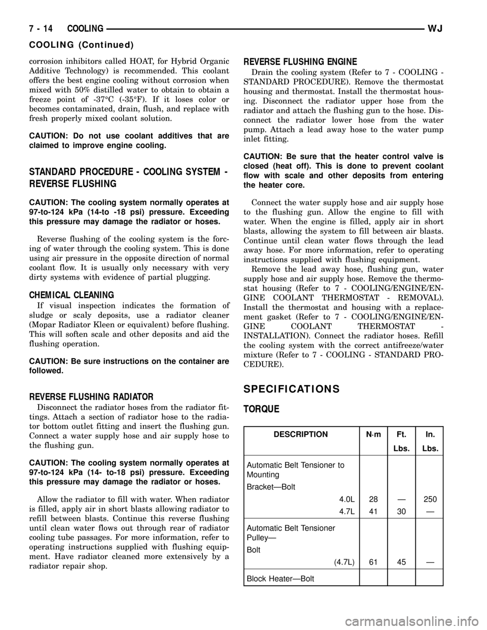
SPECIFICATIONS
TORQUE
DESCRIPTION N´m Ft. In.
Lbs. Lbs.
Automatic Belt Tensioner to
Mounting
BracketÐBolt
4.0L 28 Ð 250
4.7L 41 30 Ð
Automatic Belt Tensioner
PulleyÐ
Bolt
(4.7L) 61 45 Ð
Block HeaterÐBolt
7 - 14 COOLINGWJ
COOLING (Continued)
Page 255 of 2199

(7) After removing fan blade/viscous fan drive
assembly,do notplace viscous fan drive in horizon-
tal position. If stored horizontally, silicone fluid in
the viscous fan drive could drain into its bearing
assembly and contaminate lubricant.
CAUTION: Do not remove water pump pulley-to-wa-
ter pump bolts. This pulley is under belt tension.
(8) Remove four bolts securing fan blade assembly
to viscous fan drive .
CLEANING
Clean the fan blades using a mild soap and water.
Do not use an abrasive to clean the blades.
INSPECTION
WARNING: DO NOT ATTEMPT TO BEND OR
STRAIGHTEN FAN BLADES IF FAN IS NOT WITHIN
SPECIFICATIONS.
CAUTION: If fan blade assembly is replaced
because of mechanical damage, water pump and
viscous fan drive should also be inspected. These
components could have been damaged due to
excessive vibration.
(1) Remove fan blade assembly from viscous fan
drive unit (four bolts).(2) Lay fan on a flat surface with leading edge fac-
ing down. With tip of blade touching flat surface,
replace fan if clearance between opposite blade and
surface is greater than 2.0 mm (.090 inch). Rocking
motion of opposite blades should not exceed 2.0 mm
(.090 inch). Test all blades in this manner.
(3) Inspect fan assembly for cracks, bends, loose
rivets or broken welds. Replace fan if any damage is
found.
INSTALLATION
(1) Assemble fan blade to viscous fan drive.
Tighten mounting bolts to 27 N´m (20 ft. lbs.) torque.
(2) Thread the fan and fan drive onto the water
pump pulley.
CAUTION: When installing a serpentine accessory
drive belt, the belt MUST be routed correctly. If not,
the engine may overheat due to the water pump
rotating in the wrong direction. (Refer to 7 - COOL-
ING/ACCESSORY DRIVE/DRIVE BELTS - REMOVAL)
for correct belt routing.
ENGINE BLOCK HEATER
DESCRIPTION
DESCRIPTIONÐ4.7L ENGINE
WARNING: DO NOT OPERATE ENGINE UNLESS
BLOCK HEATER CORD HAS BEEN DISCONNECTED
FROM POWER SOURCE AND SECURED IN PLACE.
THE POWER CORD MUST BE SECURED IN ITS
RETAINING CLIPS AND ROUTED AWAY FROM
EXHAUST MANIFOLDS AND MOVING PARTS.
An optional engine block heater (Fig. 12) is avail-
able with all models. The heater is equipped with a
power cord. The cord is attached to an engine com-
partment component with tie-straps. The heater
warms the engine providing easier engine starting
and faster warm-up in low temperatures. The heater
is mounted in a core hole of the engine cylinder block
in place of a freeze plug with the heating element
immersed in engine coolant.
DESCRIPTIONÐ4.0L ENGINE
WARNING: DO NOT OPERATE ENGINE UNLESS
BLOCK HEATER CORD HAS BEEN DISCONNECTED
FROM POWER SOURCE AND SECURED IN PLACE.
THE POWER CORD MUST BE SECURED IN ITS
RETAINING CLIPS AND ROUTED AWAY FROM
EXHAUST MANIFOLDS AND MOVING PARTS.
Fig. 11 Fan and Viscous Fan Drive
1 - FAN AND FAN DRIVE
2 - WATER PUMP PULLEY
7 - 32 ENGINEWJ
RADIATOR FAN - 4.0L (Continued)
Page 288 of 2199

(2) Touch one ohmmeter test lead to a good clean
ground point on the vehicle fender. Touch the other
test lead to the outer crimp on the antenna coaxial
cable connector under the right end of the instru-
ment panel near the right cowl side inner panel.
Check the ohmmeter reading for continuity.
(3) There should be continuity. The ohmmeter
should register less than one ohm resistance. High or
infinite resistance indicates a loose, corroded, or
damaged connection between the antenna body and
the vehicle body or between the antenna body and
the antenna coaxial cable shield. If not OK, clean the
antenna body to fender mating surfaces and tighten
the antenna cap nut to specifications.
(4) Check the resistance again with an ohmmeter.
If the resistance is still more then one ohm, replace
the faulty antenna body and cable.
REMOVAL
WARNING: DISABLE THE AIRBAG SYSTEM
BEFORE ATTEMPTING ANY STEERING WHEEL,
STEERING COLUMN, SEAT BELT TENSIONER, SIDE
AIRBAG, OR INSTRUMENT PANEL COMPONENT
DIAGNOSIS OR SERVICE. DISCONNECT AND ISO-
LATE THE BATTERY NEGATIVE (GROUND) CABLE,
THEN WAIT TWO MINUTES FOR THE AIRBAG SYS-
TEM CAPACITOR TO DISCHARGE BEFORE PER-
FORMING FURTHER DIAGNOSIS OR SERVICE. THIS
IS THE ONLY SURE WAY TO DISABLE THE AIRBAG
SYSTEM. FAILURE TO TAKE THE PROPER PRE-
CAUTIONS COULD RESULT IN ACCIDENTAL AIR-
BAG DEPLOYMENT AND POSSIBLE PERSONAL
INJURY.
(1) Disconnect and isolate the battery negative
cable.
(2) Remove the scuff plate from the right front
door sill. (Refer to 23 - BODY/INTERIOR/DOOR
SILL SCUFF PLATE - REMOVAL) for the proce-
dures.
(3) Remove the trim panel from the right inner
cowl side.(Refer to 23 - BODY/INTERIOR/COWL
TRIM - REMOVAL) for the procedures.
(4) Reach under the passenger side of the instru-
ment panel near the right cowl side inner panel to
disconnect the antenna coaxial cable connector by
pulling it apart while twisting the metal connector
halves (Fig. 4). Do not pull on the cable.
(5) Remove the lower rear half of the inner liner
from the right front fender wheel house. (Refer to 23
- BODY/EXTERIOR/FRONT FENDER - REMOVAL)
for the procedures.
(6) Reach through the rear of the right front
fender wheel house opening to access and unseat the
antenna lead grommet from the hole in the right
cowl side outer panel.(7) Pull the antenna lead coaxial cable and connec-
tor out of the passenger compartment and into the
right front fender wheel house through the hole in
the right cowl side outer panel.
(8) Unscrew the antenna mast from the antenna
base (Fig. 5).
(9) Remove the plastic shroud from the antenna
base cap nut.
(10) Remove the antenna base cap nut using an
antenna nut wrench (Special Tool C-4816) (Fig. 6).
(11) Remove the antenna escutcheon from the
antenna base on the top of the right front fender.
(12) Lower the antenna base from the mounting
hole in the top of the right front fender.
(13) Remove the antenna base and lead from the
rear of the right front fender wheel house opening.
Fig. 4 Antenna Base and Lead Remove/Install
1 - BASE AND LEAD
2 - ESCUTCHEON
3 - MAST
4 - SHROUD
5 - CAP NUT
6 - RIGHT FRONT FENDER
7 - GROMMET
8 - CONNECTOR
WJAUDIO 8A - 9
ANTENNA BODY & CABLE (Continued)
Page 332 of 2199
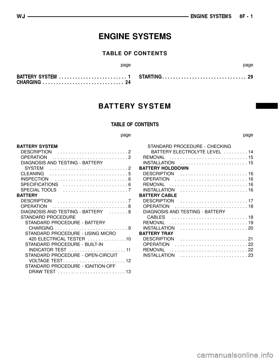
ENGINE SYSTEMS
TABLE OF CONTENTS
page page
BATTERY SYSTEM......................... 1
CHARGING.............................. 24STARTING............................... 29
BATTERY SYSTEM
TABLE OF CONTENTS
page page
BATTERY SYSTEM
DESCRIPTION..........................2
OPERATION............................2
DIAGNOSIS AND TESTING - BATTERY
SYSTEM.............................2
CLEANING.............................5
INSPECTION...........................6
SPECIFICATIONS........................6
SPECIAL TOOLS........................7
BATTERY
DESCRIPTION..........................7
OPERATION............................8
DIAGNOSIS AND TESTING - BATTERY.......8
STANDARD PROCEDURE
STANDARD PROCEDURE - BATTERY
CHARGING...........................9
STANDARD PROCEDURE - USING MICRO
420 ELECTRICAL TESTER..............10
STANDARD PROCEDURE - BUILT-IN
INDICATOR TEST.....................11
STANDARD PROCEDURE - OPEN-CIRCUIT
VOLTAGE TEST.......................12
STANDARD PROCEDURE - IGNITION-OFF
DRAW TEST.........................13STANDARD PROCEDURE - CHECKING
BATTERY ELECTROLYTE LEVEL.........14
REMOVAL.............................15
INSTALLATION.........................15
BATTERY HOLDDOWN
DESCRIPTION.........................16
OPERATION...........................16
REMOVAL.............................16
INSTALLATION.........................16
BATTERY CABLE
DESCRIPTION.........................17
OPERATION...........................18
DIAGNOSIS AND TESTING - BATTERY
CABLES............................18
REMOVAL.............................19
INSTALLATION.........................20
BATTERY TRAY
DESCRIPTION.........................21
OPERATION...........................22
REMOVAL.............................22
INSTALLATION.........................23
WJENGINE SYSTEMS 8F - 1
Page 333 of 2199

BATTERY SYSTEM
DESCRIPTION
A single 12-volt battery system is standard factory-
installed equipment on this model. All of the compo-
nents of the battery system are located within the
engine compartment of the vehicle. The service infor-
mation for the battery system in this vehicle covers
the following related components, which are covered
in further detail elsewhere in this service manual:
²Battery- The storage battery provides a reli-
able means of storing a renewable source of electrical
energy within the vehicle.
²Battery Cables- The battery cables connect
the battery terminal posts to the vehicle electrical
system.
²Battery Holddown- The battery holddown
hardware secures the battery in the battery tray in
the engine compartment.
²Battery Tray- The battery tray provides a
secure mounting location in the vehicle for the bat-
tery and an anchor point for the battery holddown
hardware.
For battery system maintenance schedules and jump
starting procedures, see the owner's manual in the vehi-
cle glove box. Optionally, refer to Lubrication and Main-
tenance for the recommended battery maintenance
schedules and for the proper battery jump starting pro-
cedures. While battery charging can be considered a
maintenance procedure, the battery charging procedures
and related information are located in the standard pro-
cedures section of this service manual. This was done
because the battery must be fully-charged before any
battery system diagnosis or testing procedures can be
performed. Refer to Standard procedures for the proper
battery charging procedures.
OPERATION
The battery system is designed to provide a safe,
efficient, reliable and mobile means of delivering and
storing electrical energy. This electrical energy is
required to operate the engine starting system, as
well as to operate many of the other vehicle acces-
sory systems for limited durations while the engine
and/or the charging system are not operating. The
battery system is also designed to provide a reserve
of electrical energy to supplement the charging sys-
tem for short durations while the engine is running
and the electrical current demands of the vehicle
exceed the output of the charging system. In addition
to delivering, and storing electrical energy for the
vehicle, the battery system serves as a capacitor and
voltage stabilizer for the vehicle electrical system. It
absorbs most abnormal or transient voltages caused
by the switching of any of the electrical components
or circuits in the vehicle.
DIAGNOSIS AND TESTING - BATTERY SYSTEM
The battery, starting, and charging systems in the
vehicle operate with one another and must be tested
as a complete system. In order for the engine to start
and the battery to maintain its charge properly, all of
the components that are used in these systems must
perform within specifications. It is important that
the battery, starting, and charging systems be thor-
oughly tested and inspected any time a battery needs
to be charged or replaced. The cause of abnormal bat-
tery discharge, overcharging or early battery failure
must be diagnosed and corrected before a battery is
replaced and before a vehicle is returned to service.
The service information for these systems has been
separated within this service manual to make it eas-
ier to locate the specific information you are seeking.
However, when attempting to diagnose any of these
systems, it is important that you keep their interde-
pendency in mind.
The diagnostic procedures used for the battery,
starting, and charging systems include the most
basic conventional diagnostic methods, to the more
sophisticated On-Board Diagnostics (OBD) built into
the Powertrain Control Module (PCM). Use of an
induction-type milliampere ammeter, a volt/ohmme-
ter, a battery charger, a carbon pile rheostat (load
tester) and a 12-volt test lamp may be required. All
OBD-sensed systems are monitored by the PCM.
Each monitored circuit is assigned a Diagnostic Trou-
ble Code (DTC). The PCM will store a DTC in elec-
tronic memory for any failure it detects. Refer to
Charging System for the proper charging system on-
board diagnostic test procedures.
MICRO 420 ELECTRICAL SYSTEM TESTER
The Micro 420 automotive battery tester is
designed to help the dealership technicians diagnose
a defective battery. Follow the instruction manual
supplied with the tester to properly diagnose a vehi-
cle. If the instruction manual is not available refer to
the standard procedure in this section, which
includes the directions for using the Micro 420 elec-
trical system tester.
8F - 2 BATTERY SYSTEMWJ
Page 334 of 2199
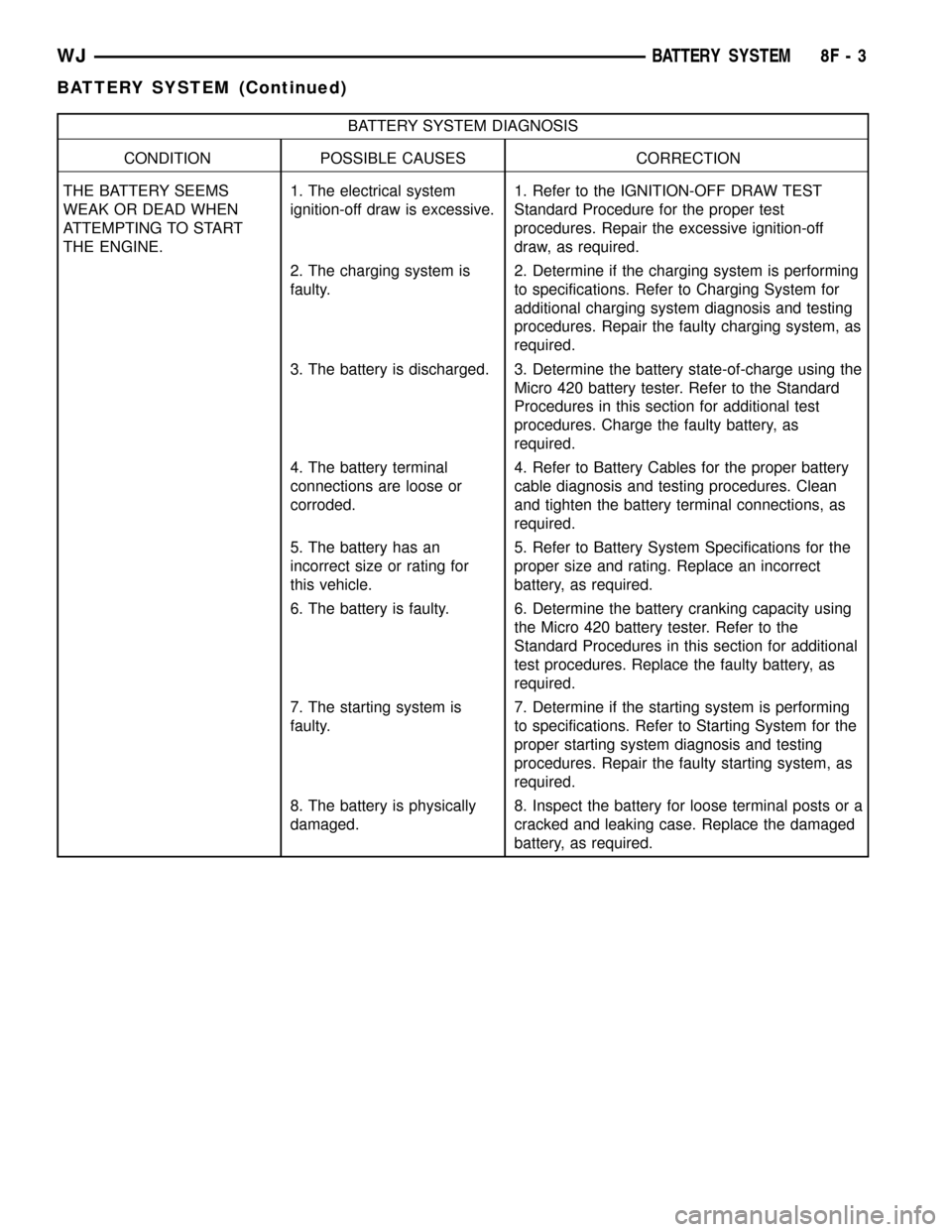
BATTERY SYSTEM DIAGNOSIS
CONDITION POSSIBLE CAUSES CORRECTION
THE BATTERY SEEMS
WEAK OR DEAD WHEN
ATTEMPTING TO START
THE ENGINE.1. The electrical system
ignition-off draw is excessive.1. Refer to the IGNITION-OFF DRAW TEST
Standard Procedure for the proper test
procedures. Repair the excessive ignition-off
draw, as required.
2. The charging system is
faulty.2. Determine if the charging system is performing
to specifications. Refer to Charging System for
additional charging system diagnosis and testing
procedures. Repair the faulty charging system, as
required.
3. The battery is discharged. 3. Determine the battery state-of-charge using the
Micro 420 battery tester. Refer to the Standard
Procedures in this section for additional test
procedures. Charge the faulty battery, as
required.
4. The battery terminal
connections are loose or
corroded.4. Refer to Battery Cables for the proper battery
cable diagnosis and testing procedures. Clean
and tighten the battery terminal connections, as
required.
5. The battery has an
incorrect size or rating for
this vehicle.5. Refer to Battery System Specifications for the
proper size and rating. Replace an incorrect
battery, as required.
6. The battery is faulty. 6. Determine the battery cranking capacity using
the Micro 420 battery tester. Refer to the
Standard Procedures in this section for additional
test procedures. Replace the faulty battery, as
required.
7. The starting system is
faulty.7. Determine if the starting system is performing
to specifications. Refer to Starting System for the
proper starting system diagnosis and testing
procedures. Repair the faulty starting system, as
required.
8. The battery is physically
damaged.8. Inspect the battery for loose terminal posts or a
cracked and leaking case. Replace the damaged
battery, as required.
WJBATTERY SYSTEM 8F - 3
BATTERY SYSTEM (Continued)
Page 335 of 2199
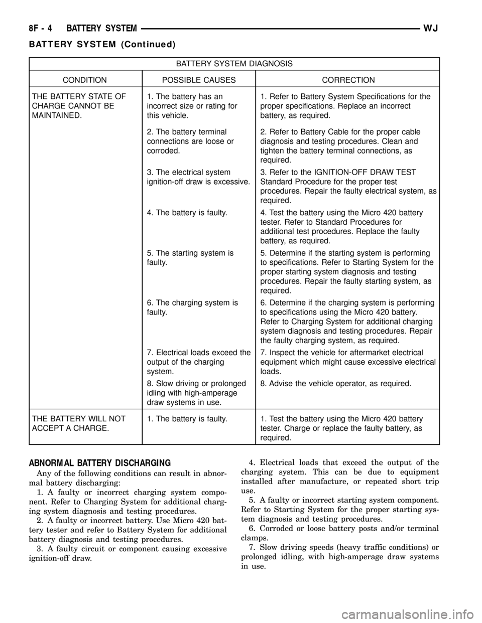
BATTERY SYSTEM DIAGNOSIS
CONDITION POSSIBLE CAUSES CORRECTION
THE BATTERY STATE OF
CHARGE CANNOT BE
MAINTAINED.1. The battery has an
incorrect size or rating for
this vehicle.1. Refer to Battery System Specifications for the
proper specifications. Replace an incorrect
battery, as required.
2. The battery terminal
connections are loose or
corroded.2. Refer to Battery Cable for the proper cable
diagnosis and testing procedures. Clean and
tighten the battery terminal connections, as
required.
3. The electrical system
ignition-off draw is excessive.3. Refer to the IGNITION-OFF DRAW TEST
Standard Procedure for the proper test
procedures. Repair the faulty electrical system, as
required.
4. The battery is faulty. 4. Test the battery using the Micro 420 battery
tester. Refer to Standard Procedures for
additional test procedures. Replace the faulty
battery, as required.
5. The starting system is
faulty.5. Determine if the starting system is performing
to specifications. Refer to Starting System for the
proper starting system diagnosis and testing
procedures. Repair the faulty starting system, as
required.
6. The charging system is
faulty.6. Determine if the charging system is performing
to specifications using the Micro 420 battery.
Refer to Charging System for additional charging
system diagnosis and testing procedures. Repair
the faulty charging system, as required.
7. Electrical loads exceed the
output of the charging
system.7. Inspect the vehicle for aftermarket electrical
equipment which might cause excessive electrical
loads.
8. Slow driving or prolonged
idling with high-amperage
draw systems in use.8. Advise the vehicle operator, as required.
THE BATTERY WILL NOT
ACCEPT A CHARGE.1. The battery is faulty. 1. Test the battery using the Micro 420 battery
tester. Charge or replace the faulty battery, as
required.
ABNORMAL BATTERY DISCHARGING
Any of the following conditions can result in abnor-
mal battery discharging:
1. A faulty or incorrect charging system compo-
nent. Refer to Charging System for additional charg-
ing system diagnosis and testing procedures.
2. A faulty or incorrect battery. Use Micro 420 bat-
tery tester and refer to Battery System for additional
battery diagnosis and testing procedures.
3. A faulty circuit or component causing excessive
ignition-off draw.4. Electrical loads that exceed the output of the
charging system. This can be due to equipment
installed after manufacture, or repeated short trip
use.
5. A faulty or incorrect starting system component.
Refer to Starting System for the proper starting sys-
tem diagnosis and testing procedures.
6. Corroded or loose battery posts and/or terminal
clamps.
7. Slow driving speeds (heavy traffic conditions) or
prolonged idling, with high-amperage draw systems
in use.
8F - 4 BATTERY SYSTEMWJ
BATTERY SYSTEM (Continued)