Specifications JEEP GRAND CHEROKEE 2002 WJ / 2.G Owner's Manual
[x] Cancel search | Manufacturer: JEEP, Model Year: 2002, Model line: GRAND CHEROKEE, Model: JEEP GRAND CHEROKEE 2002 WJ / 2.GPages: 2199, PDF Size: 76.01 MB
Page 108 of 2199

GEAR CONTACT PATTERN
The ring gear and pinion teeth contact patterns
will show if the pinion depth is correct in the hous-
ing. It will also show if the ring gear backlash has
been adjusted correctly. The backlash can be adjusted
within specifications to achieve desired tooth contact
patterns.
(1) Apply a thin coat of hydrated ferric oxide or
equivalent to the drive and coast side of the ring gear
teeth.
(2) Wrap, twist and hold a shop towel around the
pinion yoke to increase the turning resistance of the
pinion. This will provide a more distinct contact pat-
tern.
(3) With a boxed end wrench on a ring gear bolt,
rotate the differential case one complete revolution in
both directions while a load is being applied from
shop towel.
The areas on the ring gear teeth with the greatest
degree of contact against the pinion teeth will squee-
gee the compound to the areas with the least amount
of contact. Note and compare patterns on the ring
gear teeth to Gear Tooth Contact Patterns chart (Fig.
24) and adjust pinion depth and gear backlash as
necessary.
Fig. 23 BACKLASH SHIM
WJREAR AXLE - 198RBI 3 - 63
REAR AXLE - 198RBI (Continued)
Page 110 of 2199
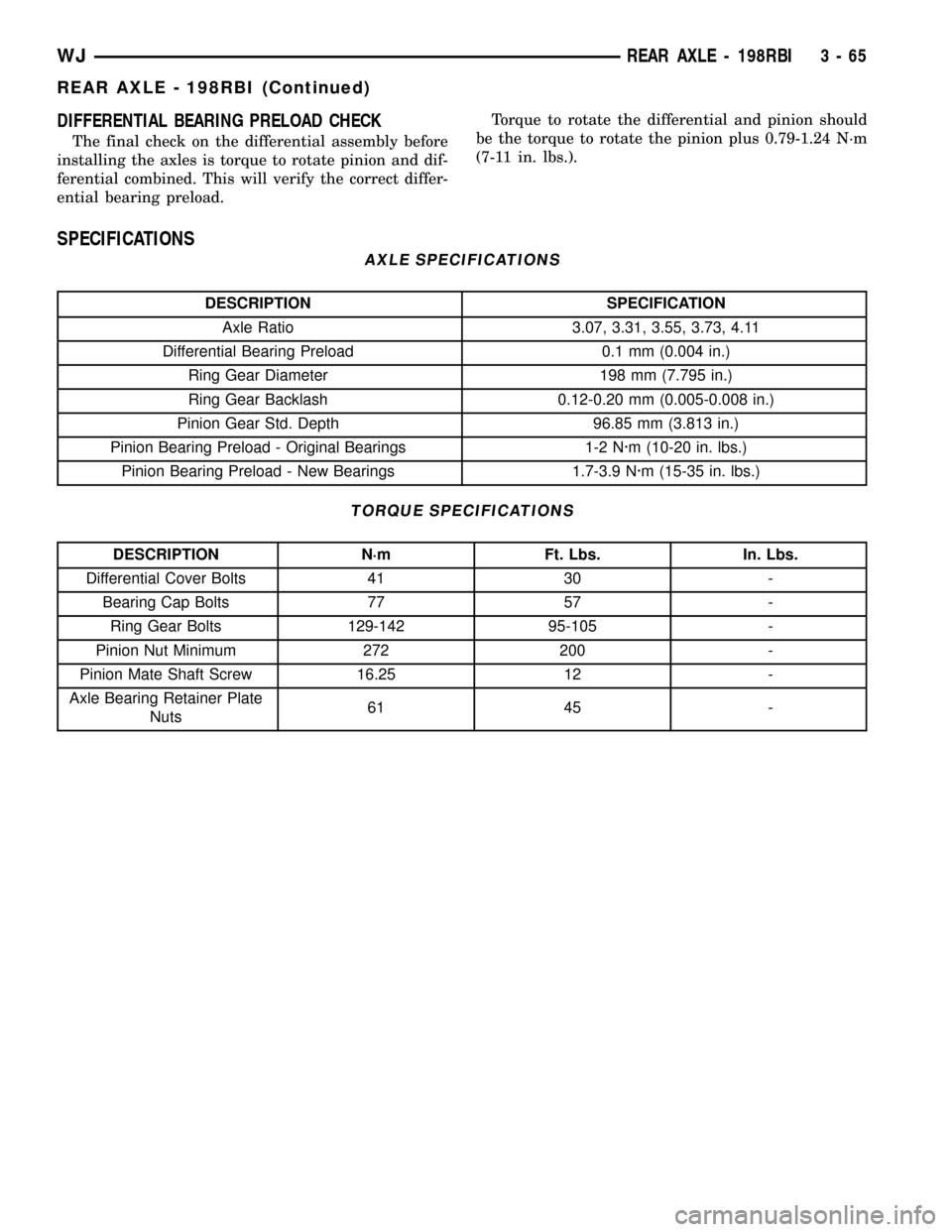
DIFFERENTIAL BEARING PRELOAD CHECK
The final check on the differential assembly before
installing the axles is torque to rotate pinion and dif-
ferential combined. This will verify the correct differ-
ential bearing preload.Torque to rotate the differential and pinion should
be the torque to rotate the pinion plus 0.79-1.24 N´m
(7-11 in. lbs.).
SPECIFICATIONS
AXLE SPECIFICATIONS
DESCRIPTION SPECIFICATION
Axle Ratio 3.07, 3.31, 3.55, 3.73, 4.11
Differential Bearing Preload 0.1 mm (0.004 in.)
Ring Gear Diameter 198 mm (7.795 in.)
Ring Gear Backlash 0.12-0.20 mm (0.005-0.008 in.)
Pinion Gear Std. Depth 96.85 mm (3.813 in.)
Pinion Bearing Preload - Original Bearings 1-2 N´m (10-20 in. lbs.)
Pinion Bearing Preload - New Bearings 1.7-3.9 N´m (15-35 in. lbs.)
TORQUE SPECIFICATIONS
DESCRIPTION N´m Ft. Lbs. In. Lbs.
Differential Cover Bolts 41 30 -
Bearing Cap Bolts 77 57 -
Ring Gear Bolts 129-142 95-105 -
Pinion Nut Minimum 272 200 -
Pinion Mate Shaft Screw 16.25 12 -
Axle Bearing Retainer Plate
Nuts61 45 -
WJREAR AXLE - 198RBI 3 - 65
REAR AXLE - 198RBI (Continued)
Page 135 of 2199

REAR AXLE - 226RBA
TABLE OF CONTENTS
page page
REAR AXLE - 226RBA
DESCRIPTION.........................90
OPERATION...........................90
DIAGNOSIS AND TESTING................92
REMOVAL.............................95
INSTALLATION.........................96
ADJUSTMENTS........................97
SPECIFICATIONS......................105
SPECIAL TOOLS.......................106
AXLE SHAFTS
REMOVAL............................109
INSTALLATION........................109
AXLE BEARINGS/SEALS
REMOVAL............................109
INSTALLATION........................110
PINION SEAL
REMOVAL............................111
INSTALLATION........................112
COLLAPSIBLE SPACER
REMOVAL............................113INSTALLATION........................114
DIFFERENTIAL
REMOVAL............................115
DISASSEMBLY........................117
ASSEMBLY...........................117
INSTALLATION........................117
DIFFERENTIAL - TRAC-LOK
DIAGNOSIS AND TESTING...............119
DISASSEMBLY........................119
CLEANING...........................121
INSPECTION.........................121
ASSEMBLY...........................121
DIFFERENTIAL CASE BEARINGS
REMOVAL............................123
INSTALLATION........................123
PINION GEAR/RING GEAR
REMOVAL............................124
INSTALLATION........................126
REAR AXLE - 226RBA
DESCRIPTION
The Rear Beam-design Aluminum (RBA) axle hous-
ing has an aluminum center casting (differential
housing) with axle shaft tubes extending from either
side. The tubes are pressed into the differential hous-
ing to form a one-piece axle housing. The axle has
semi-floating axle shafts, meaning that vehicle load
is supported by the axle shaft and bearings.
The differential case is a one-piece design. Differen-
tial bearing preload and ring gear backlash is adjusted
with selective shims. Pinion bearing preload is set and
maintained by the use of a collapsible spacer. The cover
provides a means for inspection and service.
Optional Trac-Loktdifferential differential has a
one-piece differential case, and the same internal
components as a standard differential, plus two
clutch disc packs.
Optional Vari-Loktdifferential has a one-piece dif-
ferential case which contains the gerotor pump
assembly and the clutch mechinism. The unit is ser-
viced only as an assembly.
OPERATION
The axle receives power from the transfer case
through the front propeller shaft. The front propellershaft is connected to the pinion gear which rotates
the differential through the gear mesh with the ring
gear bolted to the differential case. The engine power
is transmitted to the axle shafts through the pinion
mate and side gears. The side gears are splined to
the axle shafts.
STANDARD DIFFERENTIAL
During straight-ahead driving the differential pin-
ion gears do not rotate on the pinion mate shaft. This
occurs because input torque applied to the gears is
divided and distributed equally between the two side
gears. As a result, the pinion gears revolve with the
pinion mate shaft but do not rotate around it (Fig. 1).
When turning corners, the outside wheel must travel
a greater distance than the inside wheel to complete a
turn. The difference must be compensated for to prevent
the tires from scuffing and skidding through turns. To
accomplish this, the differential allows the axle shafts
to turn at unequal speeds (Fig. 2). In this instance, the
input torque applied to the pinion gears is not divided
equally. The pinion gears now rotate around the pinion
mate shaft in opposite directions. This allows the side
gear and axle shaft attached to the outside wheel to
rotate at a faster speed.
3 - 90 REAR AXLE - 226RBAWJ
Page 148 of 2199

(32) Position the indicator plunger against a ring
gear tooth (Fig. 22).
(33) Push and hold ring gear upward while not
allowing the pinion gear to rotate.
(34) Zero dial indicator face to pointer.
(35) Push and hold ring gear downward while not
allowing the pinion gear to rotate. Dial indicator
reading should be between 0.076 mm (0.003 in.) and
0.15 mm (0.006 in.). If backlash is not within specifi-
cations transfer the necessary amount of shim thick-
ness from one side of the housing to the other (Fig.
23).
(36) Verify differential case and ring gear runout
by measuring ring to pinion gear backlash at eight
locations around the ring gear. Readings should not
vary more than 0.05 mm (0.002 in.). If readings vary
more than specified, the ring gear or the differential
case is defective.
After the proper backlash is achieved, perform
Gear Contact Pattern procedure.
GEAR CONTACT PATTERN
The ring gear and pinion teeth contact patterns
will show if the pinion depth is correct in the axle
housing. It will also show if the ring gear backlashhas been adjusted correctly. The backlash can be
adjusted within specifications to achieve desired
tooth contact patterns.
(1) Apply a thin coat of hydrated ferric oxide or
equivalent to the drive and coast side of the ring gear
teeth.
(2) Wrap, twist and hold a shop towel around the
pinion yoke to increase the turning resistance of the
pinion. This will provide a more distinct contact pat-
tern.
(3) With a boxed end wrench on a ring gear bolt,
rotate the differential case one complete revolution in
both directions while a load is being applied from
shop towel.
The areas on the ring gear teeth with the greatest
degree of contact against the pinion teeth will squee-
gee the compound to the areas with the least amount
of contact. Note and compare patterns on the ring
gear teeth to Gear Tooth Contact Patterns chart (Fig.
24) and adjust pinion depth and gear backlash as
necessary.
Fig. 22 RING GEAR BACKLASH
1 - DIAL INDICATOR
Fig. 23 BACKLASH SHIM
WJREAR AXLE - 226RBA 3 - 103
REAR AXLE - 226RBA (Continued)
Page 150 of 2199
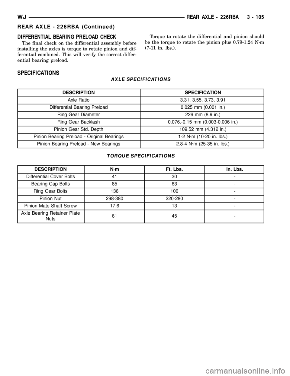
DIFFERENTIAL BEARING PRELOAD CHECK
The final check on the differential assembly before
installing the axles is torque to rotate pinion and dif-
ferential combined. This will verify the correct differ-
ential bearing preload.Torque to rotate the differential and pinion should
be the torque to rotate the pinion plus 0.79-1.24 N´m
(7-11 in. lbs.).
SPECIFICATIONS
AXLE SPECIFICATIONS
DESCRIPTION SPECIFICATION
Axle Ratio 3.31, 3.55, 3.73, 3.91
Differential Bearing Preload 0.025 mm (0.001 in.)
Ring Gear Diameter 226 mm (8.9 in.)
Ring Gear Backlash 0.076.-0.15 mm (0.003-0.006 in.)
Pinion Gear Std. Depth 109.52 mm (4.312 in.)
Pinion Bearing Preload - Original Bearings 1-2 N´m (10-20 in. lbs.)
Pinion Bearing Preload - New Bearings 2.8-4 N´m (25-35 in. lbs.)
TORQUE SPECIFICATIONS
DESCRIPTION N´m Ft. Lbs. In. Lbs.
Differential Cover Bolts 41 30 -
Bearing Cap Bolts 85 63 -
Ring Gear Bolts 136 100 -
Pinion Nut 298-380 220-280 -
Pinion Mate Shaft Screw 17.6 13 -
Axle Bearing Retainer Plate
Nuts61 45 -
WJREAR AXLE - 226RBA 3 - 105
REAR AXLE - 226RBA (Continued)
Page 176 of 2199
BRAKES
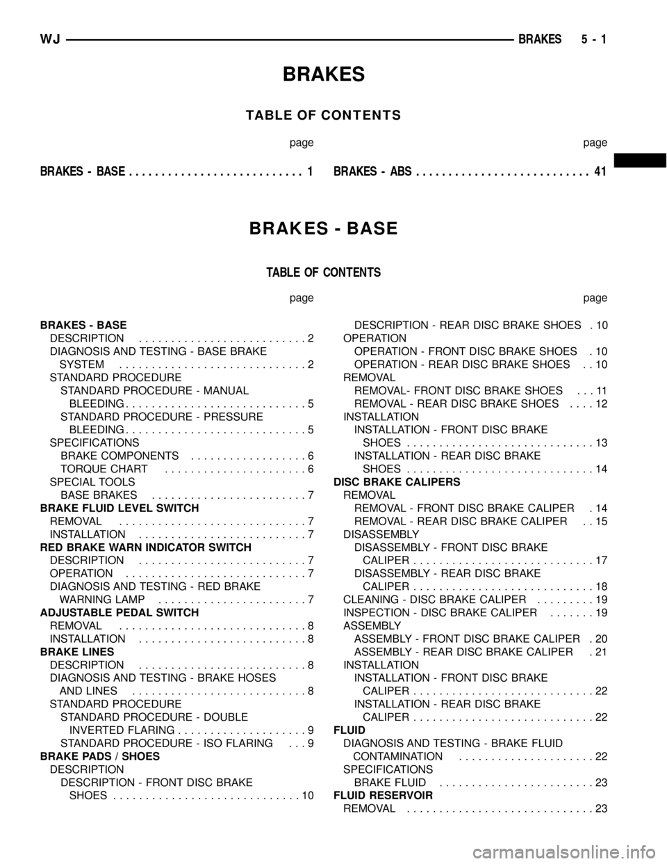
TABLE OF CONTENTS
page page
BRAKES - BASE........................... 1BRAKES - ABS........................... 41
BRAKES - BASE
TABLE OF CONTENTS
page page
BRAKES - BASE
DESCRIPTION..........................2
DIAGNOSIS AND TESTING - BASE BRAKE
SYSTEM.............................2
STANDARD PROCEDURE
STANDARD PROCEDURE - MANUAL
BLEEDING............................5
STANDARD PROCEDURE - PRESSURE
BLEEDING............................5
SPECIFICATIONS
BRAKE COMPONENTS..................6
TORQUE CHART......................6
SPECIAL TOOLS
BASE BRAKES........................7
BRAKE FLUID LEVEL SWITCH
REMOVAL.............................7
INSTALLATION..........................7
RED BRAKE WARN INDICATOR SWITCH
DESCRIPTION..........................7
OPERATION............................7
DIAGNOSIS AND TESTING - RED BRAKE
WARNING LAMP.......................7
ADJUSTABLE PEDAL SWITCH
REMOVAL.............................8
INSTALLATION..........................8
BRAKE LINES
DESCRIPTION..........................8
DIAGNOSIS AND TESTING - BRAKE HOSES
AND LINES...........................8
STANDARD PROCEDURE
STANDARD PROCEDURE - DOUBLE
INVERTED FLARING....................9
STANDARD PROCEDURE - ISO FLARING . . . 9
BRAKE PADS / SHOES
DESCRIPTION
DESCRIPTION - FRONT DISC BRAKE
SHOES.............................10DESCRIPTION - REAR DISC BRAKE SHOES . 10
OPERATION
OPERATION - FRONT DISC BRAKE SHOES . 10
OPERATION - REAR DISC BRAKE SHOES . . 10
REMOVAL
REMOVAL- FRONT DISC BRAKE SHOES . . . 11
REMOVAL - REAR DISC BRAKE SHOES....12
INSTALLATION
INSTALLATION - FRONT DISC BRAKE
SHOES.............................13
INSTALLATION - REAR DISC BRAKE
SHOES.............................14
DISC BRAKE CALIPERS
REMOVAL
REMOVAL - FRONT DISC BRAKE CALIPER . 14
REMOVAL - REAR DISC BRAKE CALIPER . . 15
DISASSEMBLY
DISASSEMBLY - FRONT DISC BRAKE
CALIPER............................17
DISASSEMBLY - REAR DISC BRAKE
CALIPER............................18
CLEANING - DISC BRAKE CALIPER.........19
INSPECTION - DISC BRAKE CALIPER.......19
ASSEMBLY
ASSEMBLY - FRONT DISC BRAKE CALIPER . 20
ASSEMBLY - REAR DISC BRAKE CALIPER . 21
INSTALLATION
INSTALLATION - FRONT DISC BRAKE
CALIPER............................22
INSTALLATION - REAR DISC BRAKE
CALIPER............................22
FLUID
DIAGNOSIS AND TESTING - BRAKE FLUID
CONTAMINATION.....................22
SPECIFICATIONS
BRAKE FLUID........................23
FLUID RESERVOIR
REMOVAL.............................23
WJBRAKES 5 - 1
Page 181 of 2199
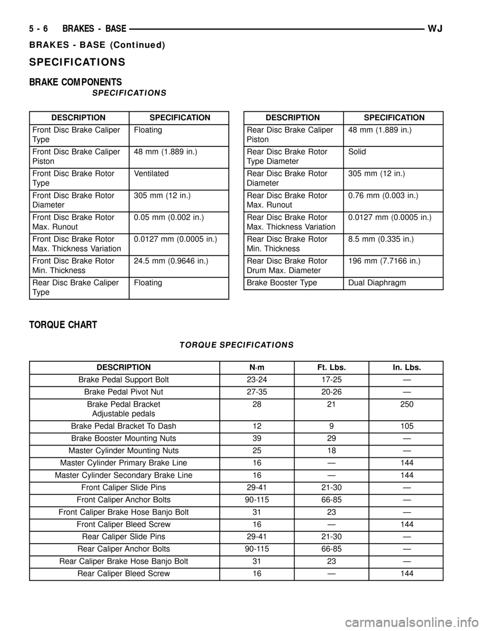
SPECIFICATIONS
BRAKE COMPONENTS
SPECIFICATIONS
DESCRIPTION SPECIFICATION
Front Disc Brake Caliper
TypeFloating
Front Disc Brake Caliper
Piston48 mm (1.889 in.)
Front Disc Brake Rotor
TypeVentilated
Front Disc Brake Rotor
Diameter305 mm (12 in.)
Front Disc Brake Rotor
Max. Runout0.05 mm (0.002 in.)
Front Disc Brake Rotor
Max. Thickness Variation0.0127 mm (0.0005 in.)
Front Disc Brake Rotor
Min. Thickness24.5 mm (0.9646 in.)
Rear Disc Brake Caliper
TypeFloatingDESCRIPTION SPECIFICATION
Rear Disc Brake Caliper
Piston48 mm (1.889 in.)
Rear Disc Brake Rotor
Type DiameterSolid
Rear Disc Brake Rotor
Diameter305 mm (12 in.)
Rear Disc Brake Rotor
Max. Runout0.76 mm (0.003 in.)
Rear Disc Brake Rotor
Max. Thickness Variation0.0127 mm (0.0005 in.)
Rear Disc Brake Rotor
Min. Thickness8.5 mm (0.335 in.)
Rear Disc Brake Rotor
Drum Max. Diameter196 mm (7.7166 in.)
Brake Booster Type Dual Diaphragm
TORQUE CHART
TORQUE SPECIFICATIONS
DESCRIPTION N´m Ft. Lbs. In. Lbs.
Brake Pedal Support Bolt 23-24 17-25 Ð
Brake Pedal Pivot Nut 27-35 20-26 Ð
Brake Pedal Bracket
Adjustable pedals28 21 250
Brake Pedal Bracket To Dash 12 9 105
Brake Booster Mounting Nuts 39 29 Ð
Master Cylinder Mounting Nuts 25 18 Ð
Master Cylinder Primary Brake Line 16 Ð 144
Master Cylinder Secondary Brake Line 16 Ð 144
Front Caliper Slide Pins 29-41 21-30 Ð
Front Caliper Anchor Bolts 90-115 66-85 Ð
Front Caliper Brake Hose Banjo Bolt 31 23 Ð
Front Caliper Bleed Screw 16 Ð 144
Rear Caliper Slide Pins 29-41 21-30 Ð
Rear Caliper Anchor Bolts 90-115 66-85 Ð
Rear Caliper Brake Hose Banjo Bolt 31 23 Ð
Rear Caliper Bleed Screw 16 Ð 144
5 - 6 BRAKES - BASEWJ
BRAKES - BASE (Continued)
Page 198 of 2199
rates into layers, there is mineral oil or other fluid
contamination of the brake fluid.
If brake fluid is contaminated, drain and thor-
oughly flush system. Replace master cylinder with
reservoir, caliper seals, HCU and all hydraulic fluid
hoses.
SPECIFICATIONS
BRAKE FLUID
The brake fluid used in this vehicle must conform
to DOT 3 specifications and SAE J1703 standards.
No other type of brake fluid is recommended or
approved for usage in the vehicle brake system. Use
only Mopar brake fluid or an equivalent from a
tightly sealed container.
CAUTION: Never use reclaimed brake fluid or fluid
from an container which has been left open. An
open container of brake fluid will absorb moisture
from the air and contaminate the fluid.
CAUTION: Never use any type of a petroleum-based
fluid in the brake hydraulic system. Use of such
type fluids will result in seal damage of the vehicle
brake hydraulic system causing a failure of the
vehicle brake system. Petroleum based fluids would
be items such as engine oil, transmission fluid,
power steering fluid, etc.
FLUID RESERVOIR
REMOVAL
(1) Remove reservoir cap and remove fluid with a
cleansuction gun.
(2) Remove the wire connector from the brake fluid
level sensor.
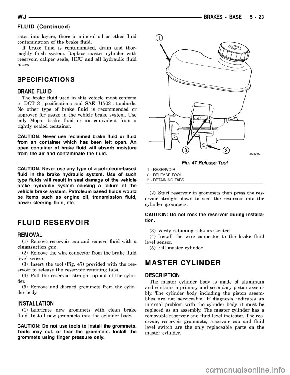
(3) Insert the tool (Fig. 47) provided with the res-
ervoir to release the reservoir retaining tabs.
(4) Pull the reservoir straight up out of the cylin-
der.
(5) Remove and discard grommets from the cylin-
der body.
INSTALLATION
(1) Lubricate new grommets with clean brake
fluid. Install new grommets into the cylinder body.
CAUTION: Do not use tools to install the grommets.
Tools may cut, or tear the grommets. Install the
grommets using finger pressure only.(2) Start reservoir in grommets then press the res-
ervoir straight down to seat the reservoir into the
cylinder grommets.
CAUTION: Do not rock the reservoir during installa-
tion.
(3) Verify retaining tabs are seated.
(4) Install the wire connector to the brake fluid
level sensor.
(5) Fill master cylinder.
MASTER CYLINDER
DESCRIPTION
The master cylinder body is made of aluminum
and contains a primary and secondary piston assem-
bly. The cylinder body including the piston assem-
blies are not serviceable. If diagnosis indicates an
internal problem with the cylinder body, it must be
replaced as an assembly. The master cylinder has a
removable reservoir and fluid level indicator. The res-
ervoir, reservoir grommets, reservoir cap and fluid
level switch are the only replaceable parts on the
master cylinder.
Fig. 47 Release Tool
1 - RESERVOIR
2 - RELEASE TOOL
3 - RETAINING TABS
WJBRAKES - BASE 5 - 23
FLUID (Continued)
Page 208 of 2199
STANDARD PROCEDURE - DISC ROTOR
MACHINING
CAUTION: For vehicles equipped with the Quadra-
Drive System, consisting of the NV-247 transfer case
and a Vari-Lok differential in the front and rear axles,
the following steps must be done prior to the use of a
hub mounted on-vehicle brake lathe. Disconnect the
driveshaft (Refer to 3 - DIFFERENTIAL & DRIVELINE/
PROPELLER SHAFT/PROPELLER SHAFT - REMOVAL)
from the respective axle on which the brake rotors are
being machined. Temporarily remove both brake cali-
pers (Refer to 5 - BRAKES/HYDRAULIC/MECHANICAL/
DISC BRAKE CALIPERS - REMOVAL) from the axle
while disc rotor machining is in process. Both steps
will prevent unnecessary loads to the hub mounted
on-vehicle lathe and speed machining times. Install a
thread lock material to the driveshaft attaching bolts
when reinstalling (Refer to 3 - DIFFERENTIAL & DRIV-
ELINE/PROPELLER SHAFT/PROPELLER SHAFT -
INSTALLATION).
NOTE: A hub mounted on-vehicle lathe is recom-
mended. This type of lathe trues the rotor to the vehi-
cles hub/bearing.
The disc brake rotor can be machined if scored or
worn. The lathe must machine both sides of the rotor
simultaneously with dual cutter heads. The rotor
mounting surface must be clean before placing on the
lathe. Equipment capable of machining only one side at
a time may produce a tapered rotor.
CAUTION: Brake rotors that do not meet minimum
thickness specifications before or after machining
must be replaced.
REMOVAL
REMOVAL - FRONT DISC BRAKE ROTOR
NOTE: Front rotors and hub/bearings are matched
mounted for minimum lateral runout. Before removing
the rotor, mark the rotor and hub/bearing to maintain
original orientation.
(1) Raise and support the vehicle.
(2) Remove wheel and tire assembly.
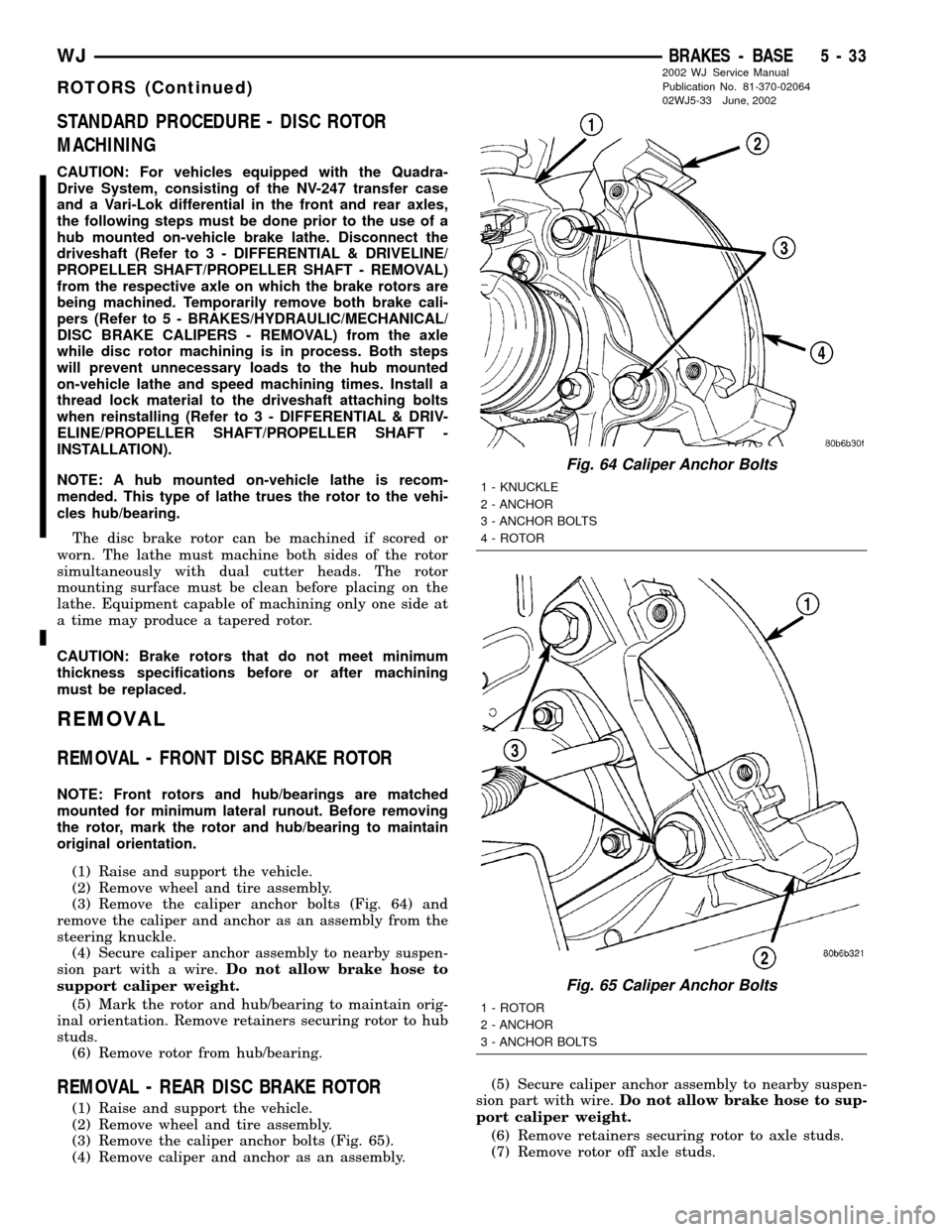
(3) Remove the caliper anchor bolts (Fig. 64) and
remove the caliper and anchor as an assembly from the
steering knuckle.
(4) Secure caliper anchor assembly to nearby suspen-
sion part with a wire.Do not allow brake hose to
support caliper weight.
(5) Mark the rotor and hub/bearing to maintain orig-
inal orientation. Remove retainers securing rotor to hub
studs.
(6) Remove rotor from hub/bearing.
REMOVAL - REAR DISC BRAKE ROTOR
(1) Raise and support the vehicle.
(2) Remove wheel and tire assembly.
(3) Remove the caliper anchor bolts (Fig. 65).
(4) Remove caliper and anchor as an assembly.(5) Secure caliper anchor assembly to nearby suspen-
sion part with wire.Do not allow brake hose to sup-
port caliper weight.
(6) Remove retainers securing rotor to axle studs.
(7) Remove rotor off axle studs.
Fig. 64 Caliper Anchor Bolts
1 - KNUCKLE
2 - ANCHOR
3 - ANCHOR BOLTS
4 - ROTOR
Fig. 65 Caliper Anchor Bolts
1 - ROTOR
2 - ANCHOR
3 - ANCHOR BOLTS
WJBRAKES - BASE 5 - 33
ROTORS (Continued)
2002 WJ Service Manual
Publication No. 81-370-02064
02WJ5-33 June, 2002
Page 216 of 2199

BRAKES - ABS
TABLE OF CONTENTS
page page
BRAKES - ABS
DESCRIPTION.........................41
OPERATION...........................41
DIAGNOSIS AND TESTING - ANTILOCK
BRAKES............................42
STANDARD PROCEDURE - BLEEDING ABS
BRAKE SYSTEM......................42
SPECIFICATIONS
TORQUE CHART......................42
ELECTRIC BRAKE
DESCRIPTION.........................43
OPERATION...........................43
FRONT WHEEL SPEED SENSOR
DESCRIPTION.........................43
OPERATION...........................43
REMOVAL.............................43INSTALLATION.........................43
G-SWITCH
DESCRIPTION.........................44
OPERATION...........................44
REMOVAL.............................44
INSTALLATION.........................44
REAR WHEEL SPEED SENSOR
DESCRIPTION.........................45
OPERATION...........................45
REMOVAL.............................45
INSTALLATION.........................46
HCU (HYDRAULIC CONTROL UNIT)
DESCRIPTION.........................46
OPERATION...........................46
REMOVAL.............................47
INSTALLATION.........................47
BRAKES - ABS
DESCRIPTION
The purpose of the antilock system is to prevent
wheel lockup during periods of high wheel slip. Pre-
venting lockup helps maintain vehicle braking action
and steering control.
The hydraulic system is a three channel design.
The front brakes are controlled individually and the
rear brakes in tandem.
The ABS electrical system is separate from other
vehicle electrical circuits. A separate controller oper-
ates the system.
OPERATION
The antilock CAB activates the system whenever
sensor signals indicate periods of high wheel slip.
High wheel slip can be described as the point where
wheel rotation begins approaching 20 to 30 percent of
actual vehicle speed during braking. Periods of high
wheel slip occur when brake stops involve high pedal
pressure and rate of vehicle deceleration.
Battery voltage is supplied to the CAB ignition ter-
minal when the ignition switch is turned to Run posi-
tion. The CAB performs a system initialization
procedure at this point. Initialization consists of a
static and dynamic self check of system electrical
components.
The static check occurs after the ignition switch is
turned to Run position. The dynamic check occurs
when vehicle road speed reaches approximately 30kph (18 mph). During the dynamic check, the CAB
briefly cycles the pump and solenoids to verify oper-
ation.
If an ABS component exhibits a fault during ini-
tialization, the CAB illuminates the amber warning
light and registers a fault code in the microprocessor
memory.
ANTILOCK BRAKING
The antilock system prevents lockup during high
slip conditions by modulating fluid apply pressure to
the wheel brake units.
Brake fluid apply pressure is modulated according
to wheel speed, degree of slip and rate of decelera-
tion. A sensor at each wheel converts wheel speed
into electrical signals. These signals are transmitted
to the CAB for processing and determination of
wheel slip and deceleration rate.
The ABS system has three fluid pressure control
channels. The front brakes are controlled separately
and the rear brakes in tandem. A speed sensor input
signal indicating a high slip condition activates the
CAB antilock program.
Two solenoid valves are used in each antilock con-
trol channel. The valves are all located within the
HCU valve body and work in pairs to either increase,
hold, or decrease apply pressure as needed in the
individual control channels.
The solenoid valves are not static during antilock
braking. They are cycled continuously to modulate
pressure. Solenoid cycle time in antilock mode can be
measured in milliseconds.
WJBRAKES - ABS 5 - 41