head bolt torque JEEP GRAND CHEROKEE 2002 WJ / 2.G Repair Manual
[x] Cancel search | Manufacturer: JEEP, Model Year: 2002, Model line: GRAND CHEROKEE, Model: JEEP GRAND CHEROKEE 2002 WJ / 2.GPages: 2199, PDF Size: 76.01 MB
Page 1493 of 2199

GEAR
TABLE OF CONTENTS
page page
GEAR
DESCRIPTION.........................16
OPERATION...........................16
REMOVAL.............................16
INSTALLATION.........................16
ADJUSTMENTS
STEERING GEAR.....................18
SPECIFICATIONS
POWER STEERING GEAR..............18
SPECIAL TOOLS
POWER STEERING GEAR..............19
PITMAN SHAFT
REMOVAL.............................20INSTALLATION.........................20
PITMAN SHAFT BEARING
REMOVAL.............................22
INSTALLATION.........................22
PITMAN SHAFT SEAL
REMOVAL.............................22
INSTALLATION.........................23
RACK PISTON/VALVE ASSEMBLY
REMOVAL.............................23
INSTALLATION.........................25
STUB SHAFT HOUSING
REMOVAL.............................25
INSTALLATION.........................25
GEAR
DESCRIPTION
The power steering gear is a recirculating ball type
gear (Fig. 1) .
The following gear components can be serviced:
²Pitman Shaft and Cover
²Pitman Shaft Bearings
²Pitman Shaft Oil Seal/Dust Seal
²Stud Shaft Housing with Seal
²O-Rings and Teflon Rings
NOTE: If rack piston assembly is damaged the gear
must be replaced.
OPERATION
The gear acts as a rolling thread between the
worm shaft and rack piston. The worm shaft is sup-
ported by a thrust bearing at the lower end and a
bearing assembly at the upper end. When the worm
shaft is turned the rack piston moves. The rack pis-
ton teeth mesh with the pitman shaft. Turning the
worm shaft turns the pitman shaft, which turns the
steering linkage.
REMOVAL
(1) Place the front wheels in the straight ahead
position with the steering wheel centered and locked.
(2) Remove the air cleaner housing,(Refer to 9 -
ENGINE/AIR INTAKE SYSTEM/AIR CLEANER
HOUSING - REMOVAL).
(3) Drain or siphon the power steering system.(4) Remove the pressure and return lines (Fig.
2)from the steering gear. Refer to hose removal in
this section.
(5) Remove the column coupler shaft bolt (Fig.
2)and remove the shaft from the gear.
(6) Raise and support the vehicle.
(7) Remove the left front wheel and tire assembly.
(8) Remove the pitman arm from gear with Puller
C-4150A.
(9) Remove the windshield washer reservoir,(Refer
to 8 - ELECTRICAL/WIPERS/WASHERS/WASHER
RESERVOIR - REMOVAL).
(10) Remove the steering gear mounting bolts.
Remove the steering gear out of the engine compart-
ment (Fig. 3).
INSTALLATION
(1) Position the steering gear on the frame rail and
install the bolts. Tighten the bolts to 108 N´m (80 ft.
lbs.) torque.
(2) Install the pitman arm and tighten nut to 251
N´m (185 ft. lbs.).
(3) Install windshield washer reservoir,(Refer to 8 -
ELECTRICAL/WIPERS/WASHERS/WASHER RES-
ERVOIR - INSTALLATION).
(4) Install the wheel and tire assembly.
(5) Remove the support and lower the vehicle.
(6) Install the pressure and return hoses to the
steering gear and tighten to 20-38 N´m (14-28 ft.
lbs.).
(7) Install the column coupler shaft.
(8) Install the air cleaner housing,(Refer to 9 -
ENGINE/AIR INTAKE SYSTEM/AIR CLEANER
HOUSING - INSTALLATION).
19 - 16 GEARWJ
Page 1548 of 2199
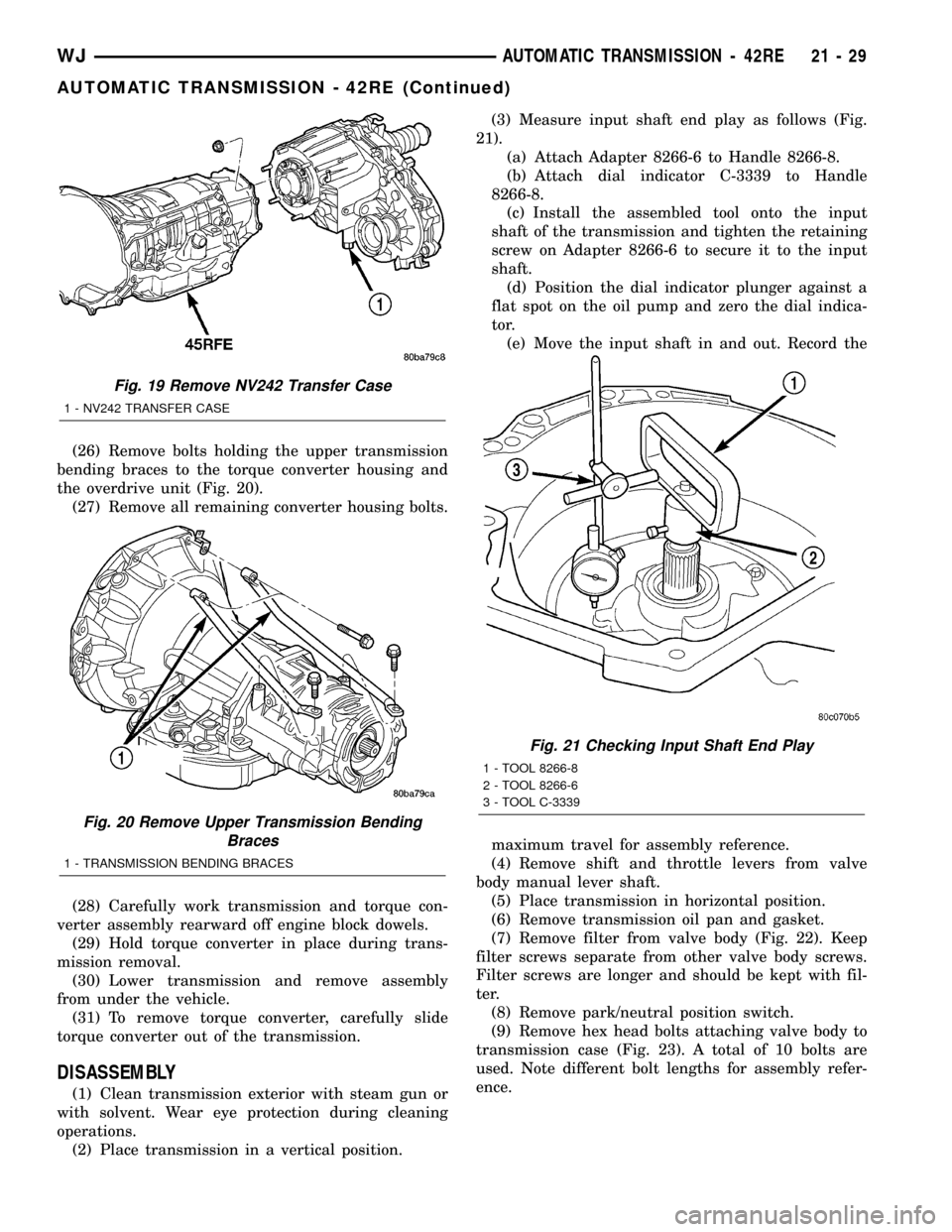
(26) Remove bolts holding the upper transmission
bending braces to the torque converter housing and
the overdrive unit (Fig. 20).
(27) Remove all remaining converter housing bolts.
(28) Carefully work transmission and torque con-
verter assembly rearward off engine block dowels.
(29) Hold torque converter in place during trans-
mission removal.
(30) Lower transmission and remove assembly
from under the vehicle.
(31) To remove torque converter, carefully slide
torque converter out of the transmission.
DISASSEMBLY
(1) Clean transmission exterior with steam gun or
with solvent. Wear eye protection during cleaning
operations.
(2) Place transmission in a vertical position.(3) Measure input shaft end play as follows (Fig.
21).
(a) Attach Adapter 8266-6 to Handle 8266-8.
(b) Attach dial indicator C-3339 to Handle
8266-8.
(c) Install the assembled tool onto the input
shaft of the transmission and tighten the retaining
screw on Adapter 8266-6 to secure it to the input
shaft.
(d) Position the dial indicator plunger against a
flat spot on the oil pump and zero the dial indica-
tor.
(e) Move the input shaft in and out. Record the
maximum travel for assembly reference.
(4) Remove shift and throttle levers from valve
body manual lever shaft.
(5) Place transmission in horizontal position.
(6) Remove transmission oil pan and gasket.
(7) Remove filter from valve body (Fig. 22). Keep
filter screws separate from other valve body screws.
Filter screws are longer and should be kept with fil-
ter.
(8) Remove park/neutral position switch.
(9) Remove hex head bolts attaching valve body to
transmission case (Fig. 23). A total of 10 bolts are
used. Note different bolt lengths for assembly refer-
ence.
Fig. 19 Remove NV242 Transfer Case
1 - NV242 TRANSFER CASE
Fig. 20 Remove Upper Transmission Bending
Braces
1 - TRANSMISSION BENDING BRACES
Fig. 21 Checking Input Shaft End Play
1 - TOOL 8266-8
2 - TOOL 8266-6
3 - TOOL C-3339
WJAUTOMATIC TRANSMISSION - 42RE 21 - 29
AUTOMATIC TRANSMISSION - 42RE (Continued)
Page 1714 of 2199
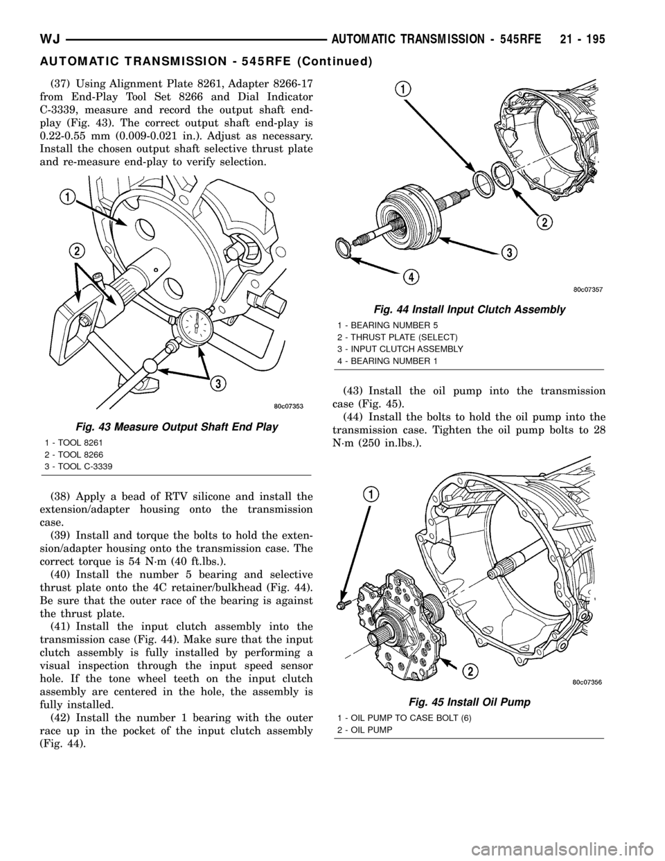
(37) Using Alignment Plate 8261, Adapter 8266-17
from End-Play Tool Set 8266 and Dial Indicator
C-3339, measure and record the output shaft end-
play (Fig. 43). The correct output shaft end-play is
0.22-0.55 mm (0.009-0.021 in.). Adjust as necessary.
Install the chosen output shaft selective thrust plate
and re-measure end-play to verify selection.
(38) Apply a bead of RTV silicone and install the
extension/adapter housing onto the transmission
case.
(39) Install and torque the bolts to hold the exten-
sion/adapter housing onto the transmission case. The
correct torque is 54 N´m (40 ft.lbs.).
(40) Install the number 5 bearing and selective
thrust plate onto the 4C retainer/bulkhead (Fig. 44).
Be sure that the outer race of the bearing is against
the thrust plate.
(41) Install the input clutch assembly into the
transmission case (Fig. 44). Make sure that the input
clutch assembly is fully installed by performing a
visual inspection through the input speed sensor
hole. If the tone wheel teeth on the input clutch
assembly are centered in the hole, the assembly is
fully installed.
(42) Install the number 1 bearing with the outer
race up in the pocket of the input clutch assembly
(Fig. 44).(43) Install the oil pump into the transmission
case (Fig. 45).
(44) Install the bolts to hold the oil pump into the
transmission case. Tighten the oil pump bolts to 28
N´m (250 in.lbs.).
Fig. 43 Measure Output Shaft End Play
1 - TOOL 8261
2 - TOOL 8266
3 - TOOL C-3339
Fig. 44 Install Input Clutch Assembly
1 - BEARING NUMBER 5
2 - THRUST PLATE (SELECT)
3 - INPUT CLUTCH ASSEMBLY
4 - BEARING NUMBER 1
Fig. 45 Install Oil Pump
1 - OIL PUMP TO CASE BOLT (6)
2 - OIL PUMP
WJAUTOMATIC TRANSMISSION - 545RFE 21 - 195
AUTOMATIC TRANSMISSION - 545RFE (Continued)
Page 1958 of 2199
INSTALLATION
(1) Position seat on floor pan.
(2) If equipped, connect power seat wire harness
connector.
(3) Install rear bolts attaching seat to floor pan.
Tighten bolts to 40 N´m (30 ft. lbs.) torque.
(4) If equipped, install cover on seat track.
(5) Move seat to full rearward position.
(6) Install front bolts attaching seat to floor pan.
Tighten bolts to 40 N´m (30 ft. lbs.) torque.
FRONT SEAT BACK
REMOVAL
(1) Move seat to full rearward position.
(2) Remove inboard bolt attaching seat back frame
to seat cushion frame.
(3) Move seat to full forward position.
(4) Move seat back to full recline position.
(5) Remove screws attaching seat side shield to
seat frame.
(6) Disconnect wire harness connector from
recliner motor, if equipped.
(7) From the underside of the seat, disconnect the
wire harness connector for the power lumber and/or
heated seat, if equipped.
(8) Remove outboard bolts attaching recliner to
seat cushion frame.
(9) Route the power lumber and/or heated seat
harness through the seat cushion cover, if equipped.
(10) Separate seat back from seat cushion.
INSTALLATION
(1) Position seat back on seat cushion.
(2) Route the power lumber and heater harness
through the seat cushion cover, if equipped.
(3) Install recliner bolts attaching seat back frame
to seat cushion frame. Tighten bolts to 28 N´m (20 ft.
lbs.) torque.
(4) Install the inboard bolt attaching seat back
frame to seat cushion frame. Tighten bolt to 47N´m
(35 ft.lbs.).
(5) Connect wire harness connector to recliner
motor and/or heated seat, if equipped.
(6) From the underside of the seat, connect the
power lumber and/or heated seat wire harness con-
nector to the seat harness, if equipped.
(7) Install screws attaching seat side shield to seat
frame.
FRONT SEAT BACK COVER
REMOVAL
(1) Remove head restraint (Refer to 23 - BODY/
SEATS/FRONT HEADREST - REMOVAL).
(2) Using a trim stick, carefully pry head restraint
release button caps from the top of seat back.
(3) Remove seat back (Refer to 23 - BODY/SEATS/
FRONT SEAT BACK - REMOVAL).
(4) Disengage J-strap at base of seat back.
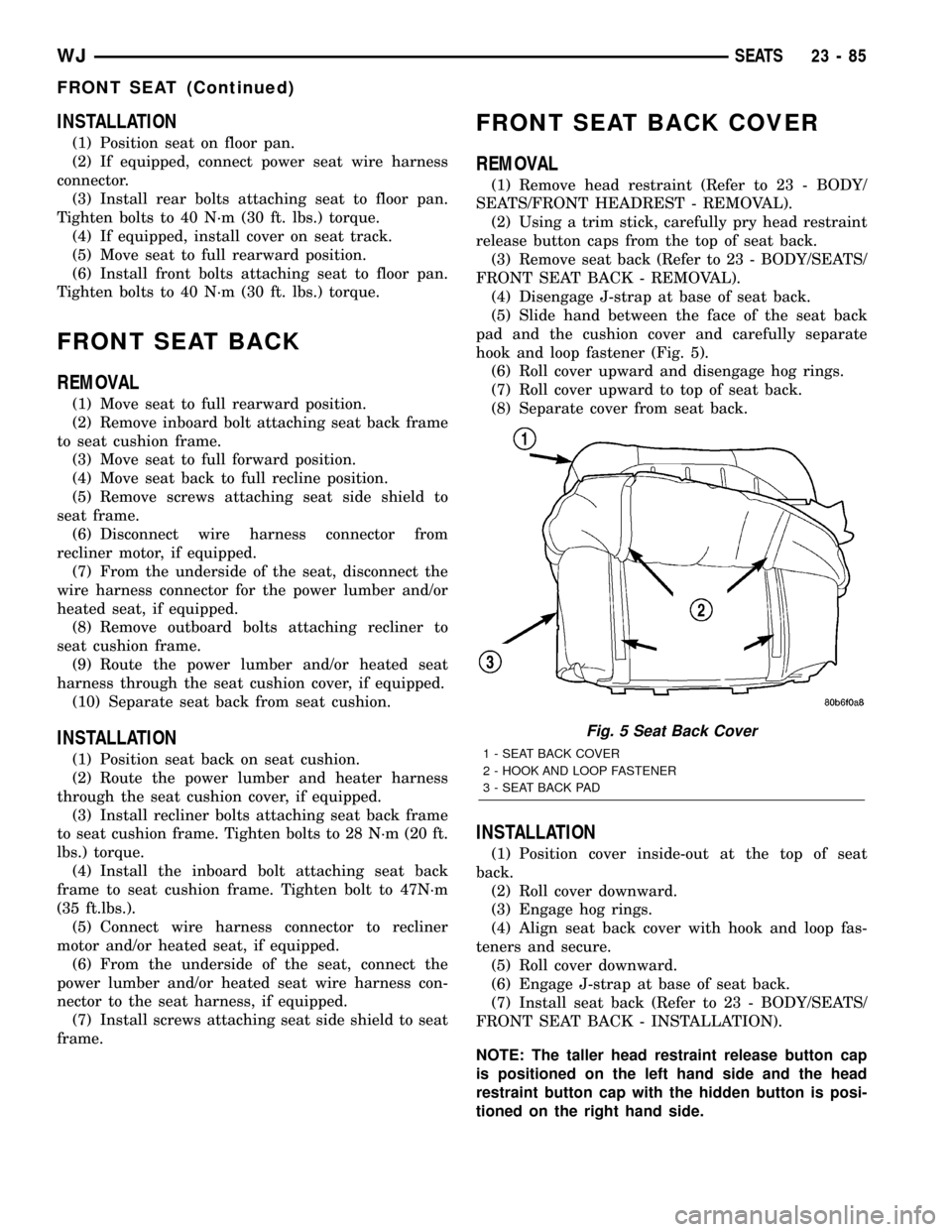
(5) Slide hand between the face of the seat back
pad and the cushion cover and carefully separate
hook and loop fastener (Fig. 5).
(6) Roll cover upward and disengage hog rings.
(7) Roll cover upward to top of seat back.
(8) Separate cover from seat back.
INSTALLATION
(1) Position cover inside-out at the top of seat
back.
(2) Roll cover downward.
(3) Engage hog rings.
(4) Align seat back cover with hook and loop fas-
teners and secure.
(5) Roll cover downward.
(6) Engage J-strap at base of seat back.
(7) Install seat back (Refer to 23 - BODY/SEATS/
FRONT SEAT BACK - INSTALLATION).
NOTE: The taller head restraint release button cap
is positioned on the left hand side and the head
restraint button cap with the hidden button is posi-
tioned on the right hand side.
Fig. 5 Seat Back Cover
1 - SEAT BACK COVER
2 - HOOK AND LOOP FASTENER
3 - SEAT BACK PAD
WJSEATS 23 - 85
FRONT SEAT (Continued)
Page 1959 of 2199
(8) Position head restraint release button caps on
head restraint sleeves and press to secure.
(9) Install head restraint (Refer to 23 - BODY/
SEATS/FRONT HEADREST - INSTALLATION).
FRONT SEAT CUSHION/COVER
REMOVAL
(1) Remove seat from vehicle (Refer to 23 - BODY/
SEATS/FRONT SEAT - REMOVAL).
(2) Remove seat back (Refer to 23 - BODY/SEATS/
FRONT SEAT BACK - REMOVAL).
(3) Disengage J-straps attaching cushion cover to
seat cushion frame.
(4) Disengage hog rings attaching cushion cover to
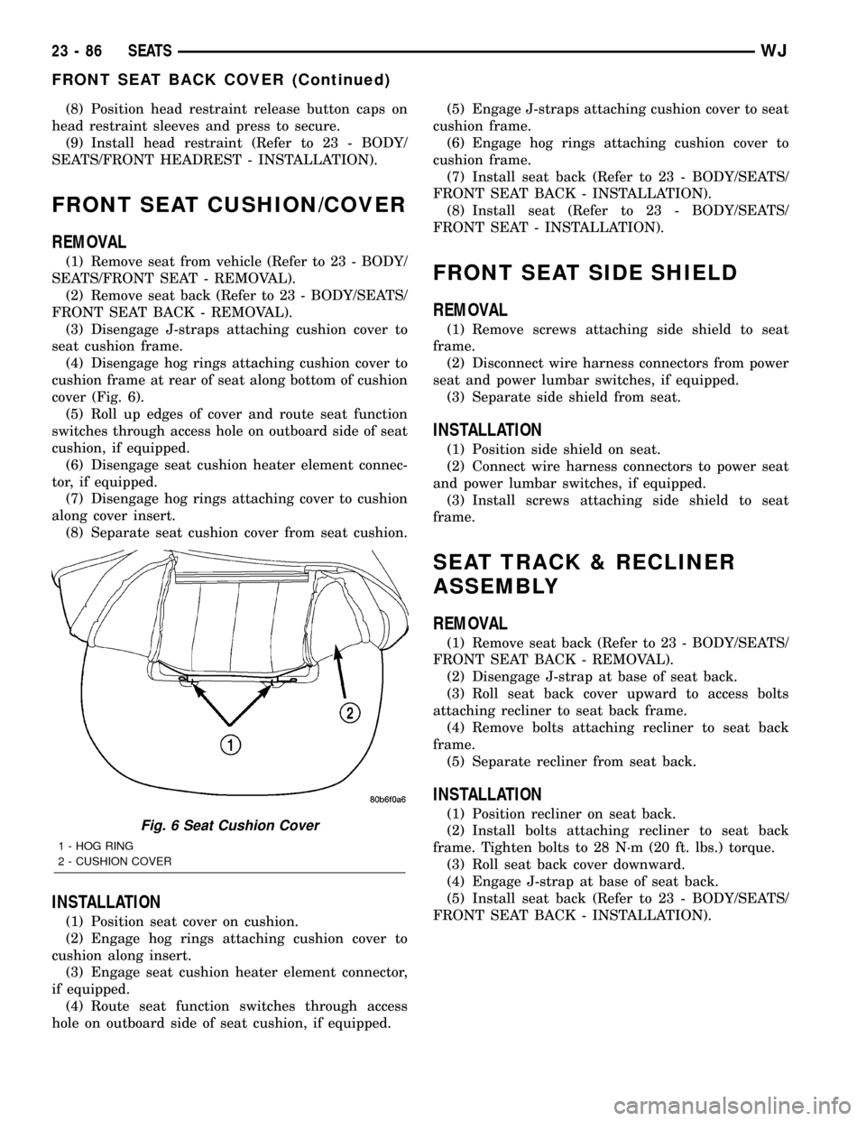
cushion frame at rear of seat along bottom of cushion
cover (Fig. 6).
(5) Roll up edges of cover and route seat function
switches through access hole on outboard side of seat
cushion, if equipped.
(6) Disengage seat cushion heater element connec-
tor, if equipped.
(7) Disengage hog rings attaching cover to cushion
along cover insert.
(8) Separate seat cushion cover from seat cushion.
INSTALLATION
(1) Position seat cover on cushion.
(2) Engage hog rings attaching cushion cover to
cushion along insert.
(3) Engage seat cushion heater element connector,
if equipped.
(4) Route seat function switches through access
hole on outboard side of seat cushion, if equipped.(5) Engage J-straps attaching cushion cover to seat
cushion frame.
(6) Engage hog rings attaching cushion cover to
cushion frame.
(7) Install seat back (Refer to 23 - BODY/SEATS/
FRONT SEAT BACK - INSTALLATION).
(8) Install seat (Refer to 23 - BODY/SEATS/
FRONT SEAT - INSTALLATION).
FRONT SEAT SIDE SHIELD
REMOVAL
(1) Remove screws attaching side shield to seat
frame.
(2) Disconnect wire harness connectors from power
seat and power lumbar switches, if equipped.
(3) Separate side shield from seat.
INSTALLATION
(1) Position side shield on seat.
(2) Connect wire harness connectors to power seat
and power lumbar switches, if equipped.
(3) Install screws attaching side shield to seat
frame.
SEAT TRACK & RECLINER
ASSEMBLY
REMOVAL
(1) Remove seat back (Refer to 23 - BODY/SEATS/
FRONT SEAT BACK - REMOVAL).
(2) Disengage J-strap at base of seat back.
(3) Roll seat back cover upward to access bolts
attaching recliner to seat back frame.
(4) Remove bolts attaching recliner to seat back
frame.
(5) Separate recliner from seat back.
INSTALLATION
(1) Position recliner on seat back.
(2) Install bolts attaching recliner to seat back
frame. Tighten bolts to 28 N´m (20 ft. lbs.) torque.
(3) Roll seat back cover downward.
(4) Engage J-strap at base of seat back.
(5) Install seat back (Refer to 23 - BODY/SEATS/
FRONT SEAT BACK - INSTALLATION).Fig. 6 Seat Cushion Cover
1 - HOG RING
2 - CUSHION COVER
23 - 86 SEATSWJ
FRONT SEAT BACK COVER (Continued)
Page 1962 of 2199
REAR HEADREST SLEEVE
REMOVAL
(1) Remove seat back (Refer to 23 - BODY/SEATS/
REAR SEAT BACK - REMOVAL).
(2) Remove head rest (Refer to 23 - BODY/SEATS/
REAR HEADREST - REMOVAL).
(3) Remove head rest caps.
(4) Remove seat back cover (Refer to 23 - BODY/
SEATS/REAR SEAT BACK COVER - REMOVAL).
(5) Rotate head rest sleeve 1/4 turn counter-clock-
wise to release retaining tab.
(6) Pull sleeve from seat back frame.
INSTALLATION
(1) Position sleeve in seat back frame.
(2) Rotate head rest sleeve 1/4 turn clockwise to
engage retaining tab.
(3) Install seat back cover (Refer to 23 - BODY/
SEATS/REAR SEAT BACK COVER - INSTALLA-
TION).
(4) Install head rest caps.
NOTE: The head rest cap with the taller button is
always on the inboard side of the seat back.
(5) Install the head rest (Refer to 23 - BODY/
SEATS/REAR HEADREST - INSTALLATION).
NOTE: The folding head rest release knob is always
on the outboard side.
(6) Install the seat back (Refer to 23 - BODY/
SEATS/REAR SEAT BACK - INSTALLATION).
REAR SEAT BACK
REMOVAL
(1) Move rear seat cushions to forward cargo posi-
tion.
(2) Remove bolts attaching seatback side support
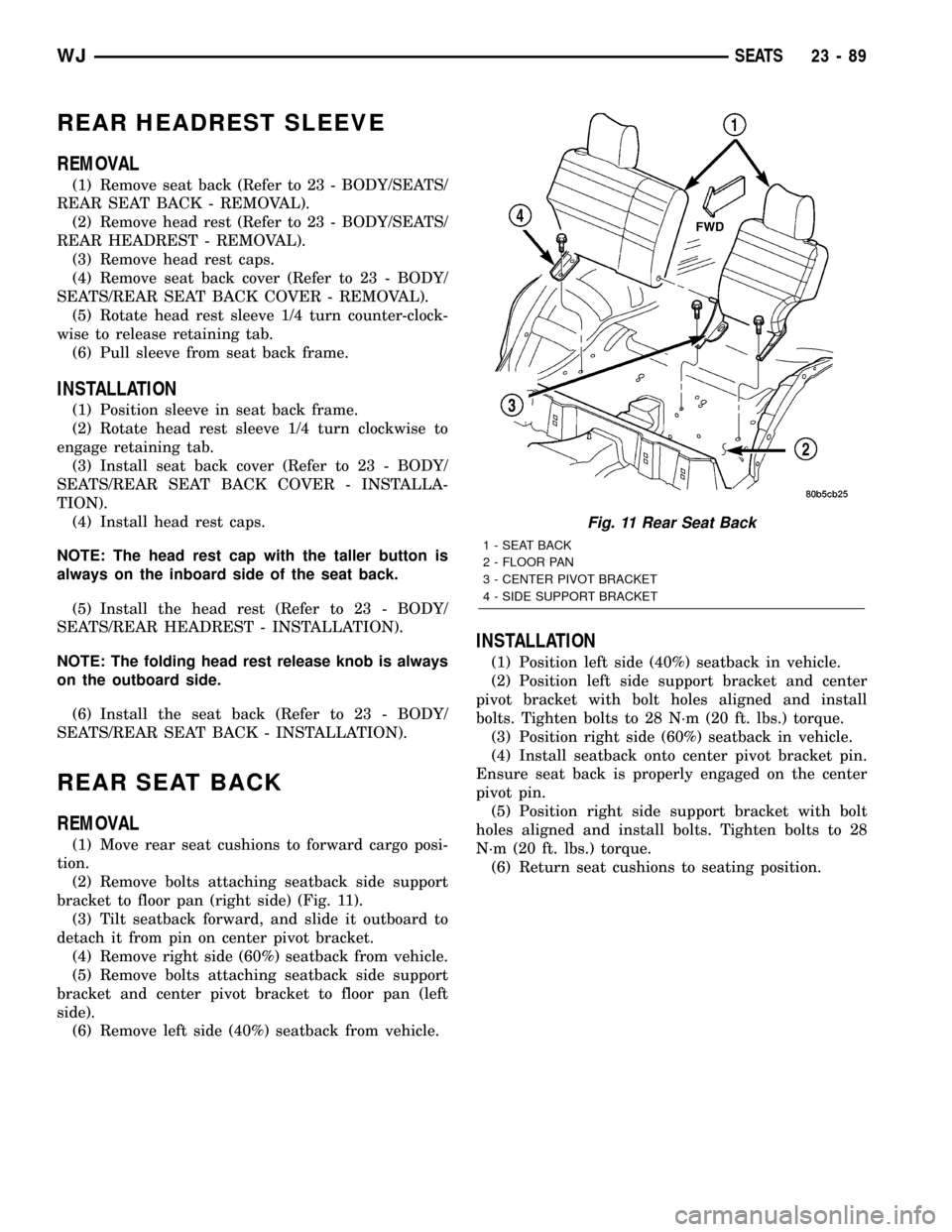
bracket to floor pan (right side) (Fig. 11).
(3) Tilt seatback forward, and slide it outboard to
detach it from pin on center pivot bracket.
(4) Remove right side (60%) seatback from vehicle.
(5) Remove bolts attaching seatback side support
bracket and center pivot bracket to floor pan (left
side).
(6) Remove left side (40%) seatback from vehicle.
INSTALLATION
(1) Position left side (40%) seatback in vehicle.
(2) Position left side support bracket and center
pivot bracket with bolt holes aligned and install
bolts. Tighten bolts to 28 N´m (20 ft. lbs.) torque.
(3) Position right side (60%) seatback in vehicle.
(4) Install seatback onto center pivot bracket pin.
Ensure seat back is properly engaged on the center
pivot pin.
(5) Position right side support bracket with bolt
holes aligned and install bolts. Tighten bolts to 28
N´m (20 ft. lbs.) torque.
(6) Return seat cushions to seating position.
Fig. 11 Rear Seat Back
1 - SEAT BACK
2 - FLOOR PAN
3 - CENTER PIVOT BRACKET
4 - SIDE SUPPORT BRACKET
WJSEATS 23 - 89
Page 1963 of 2199
REAR SEAT BACK COVER
REMOVAL
(1) Remove seat back (Refer to 23 - BODY/SEATS/
REAR SEAT BACK - REMOVAL).
(2) Remove head restraint (Refer to 23 - BODY/
SEATS/REAR HEADREST - REMOVAL).
(3) Remove head restraint caps.
(4) Disengage J-straps on outboard side of seat
back.
(5) Disengage J-straps at base of seat back.
(6) Remove screws attaching latch release handle
to seat back frame.
(7) Roll seat back cover upward.
(8) Disengage hook and loop fasteners attaching
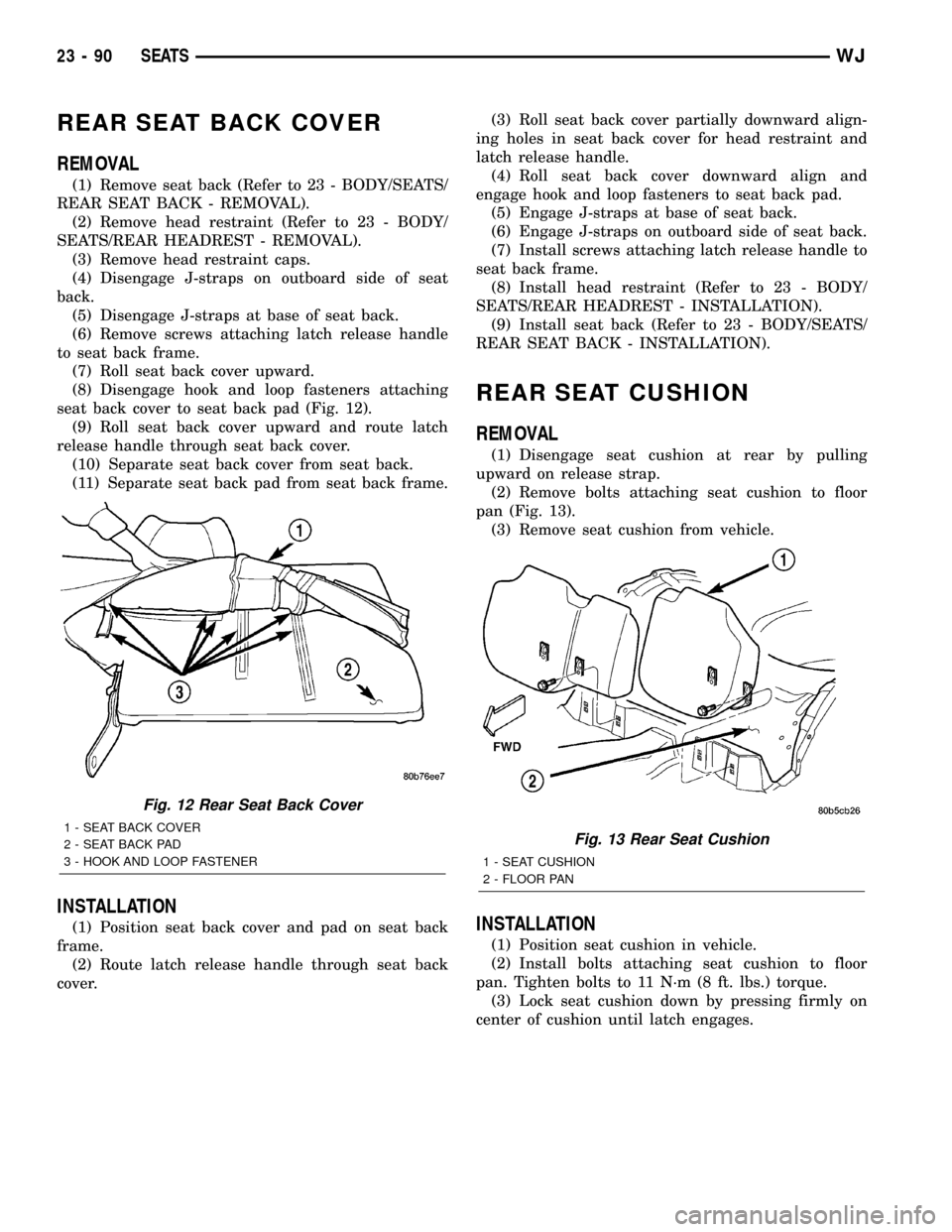
seat back cover to seat back pad (Fig. 12).
(9) Roll seat back cover upward and route latch
release handle through seat back cover.
(10) Separate seat back cover from seat back.
(11) Separate seat back pad from seat back frame.
INSTALLATION
(1) Position seat back cover and pad on seat back
frame.
(2) Route latch release handle through seat back
cover.(3) Roll seat back cover partially downward align-
ing holes in seat back cover for head restraint and
latch release handle.
(4) Roll seat back cover downward align and
engage hook and loop fasteners to seat back pad.
(5) Engage J-straps at base of seat back.
(6) Engage J-straps on outboard side of seat back.
(7) Install screws attaching latch release handle to
seat back frame.
(8) Install head restraint (Refer to 23 - BODY/
SEATS/REAR HEADREST - INSTALLATION).
(9) Install seat back (Refer to 23 - BODY/SEATS/
REAR SEAT BACK - INSTALLATION).
REAR SEAT CUSHION
REMOVAL
(1) Disengage seat cushion at rear by pulling
upward on release strap.
(2) Remove bolts attaching seat cushion to floor
pan (Fig. 13).
(3) Remove seat cushion from vehicle.
INSTALLATION
(1) Position seat cushion in vehicle.
(2) Install bolts attaching seat cushion to floor
pan. Tighten bolts to 11 N´m (8 ft. lbs.) torque.
(3) Lock seat cushion down by pressing firmly on
center of cushion until latch engages.
Fig. 12 Rear Seat Back Cover
1 - SEAT BACK COVER
2 - SEAT BACK PAD
3 - HOOK AND LOOP FASTENERFig. 13 Rear Seat Cushion
1 - SEAT CUSHION
2 - FLOOR PAN
23 - 90 SEATSWJ
Page 2141 of 2199
(7) Raise the vehicle on a hoist.
(8) Remove the front splash shield (if equipped).
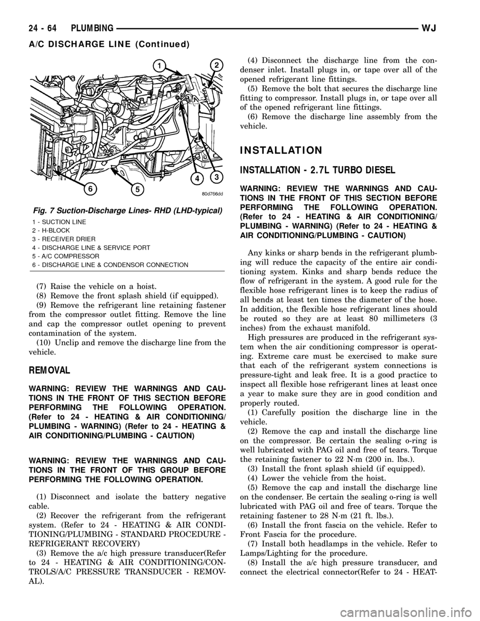
(9) Remove the refrigerant line retaining fastener
from the compressor outlet fitting. Remove the line
and cap the compressor outlet opening to prevent
contamination of the system.
(10) Unclip and remove the discharge line from the
vehicle.
REMOVAL
WARNING: REVIEW THE WARNINGS AND CAU-
TIONS IN THE FRONT OF THIS SECTION BEFORE
PERFORMING THE FOLLOWING OPERATION.
(Refer to 24 - HEATING & AIR CONDITIONING/
PLUMBING - WARNING) (Refer to 24 - HEATING &
AIR CONDITIONING/PLUMBING - CAUTION)
WARNING: REVIEW THE WARNINGS AND CAU-
TIONS IN THE FRONT OF THIS GROUP BEFORE
PERFORMING THE FOLLOWING OPERATION.
(1) Disconnect and isolate the battery negative
cable.
(2) Recover the refrigerant from the refrigerant
system. (Refer to 24 - HEATING & AIR CONDI-
TIONING/PLUMBING - STANDARD PROCEDURE -
REFRIGERANT RECOVERY)
(3) Remove the a/c high pressure transducer(Refer
to 24 - HEATING & AIR CONDITIONING/CON-
TROLS/A/C PRESSURE TRANSDUCER - REMOV-
AL).(4) Disconnect the discharge line from the con-
denser inlet. Install plugs in, or tape over all of the
opened refrigerant line fittings.
(5) Remove the bolt that secures the discharge line
fitting to compressor. Install plugs in, or tape over all
of the opened refrigerant line fittings.
(6) Remove the discharge line assembly from the
vehicle.
INSTALLATION
INSTALLATION - 2.7L TURBO DIESEL
WARNING: REVIEW THE WARNINGS AND CAU-
TIONS IN THE FRONT OF THIS SECTION BEFORE
PERFORMING THE FOLLOWING OPERATION.
(Refer to 24 - HEATING & AIR CONDITIONING/
PLUMBING - WARNING) (Refer to 24 - HEATING &
AIR CONDITIONING/PLUMBING - CAUTION)
Any kinks or sharp bends in the refrigerant plumb-
ing will reduce the capacity of the entire air condi-
tioning system. Kinks and sharp bends reduce the
flow of refrigerant in the system. A good rule for the
flexible hose refrigerant lines is to keep the radius of
all bends at least ten times the diameter of the hose.
In addition, the flexible hose refrigerant lines should
be routed so they are at least 80 millimeters (3
inches) from the exhaust manifold.
High pressures are produced in the refrigerant sys-
tem when the air conditioning compressor is operat-
ing. Extreme care must be exercised to make sure
that each of the refrigerant system connections is
pressure-tight and leak free. It is a good practice to
inspect all flexible hose refrigerant lines at least once
a year to make sure they are in good condition and
properly routed.
(1) Carefully position the discharge line in the
vehicle.
(2) Remove the cap and install the discharge line
on the compressor. Be certain the sealing o-ring is
well lubricated with PAG oil and free of tears. Torque
the retaining fastener to 22 N´m (200 in. lbs.).
(3) Install the front splash shield (if equipped).
(4) Lower the vehicle from the hoist.
(5) Remove the cap and install the discharge line
on the condenser. Be certain the sealing o-ring is well
lubricated with PAG oil and free of tears. Torque the
retaining fastener to 28 N´m (21 ft. lbs.).
(6) Install the front fascia on the vehicle. Refer to
Front Fascia for the procedure.
(7) Install both headlamps in the vehicle. Refer to
Lamps/Lighting for the procedure.
(8) Install the a/c high pressure transducer, and
connect the electrical connector(Refer to 24 - HEAT-
Fig. 7 Suction-Discharge Lines- RHD (LHD-typical)
1 - SUCTION LINE
2 - H-BLOCK
3 - RECEIVER DRIER
4 - DISCHARGE LINE & SERVICE PORT
5 - A/C COMPRESSOR
6 - DISCHARGE LINE & CONDENSOR CONNECTION
24 - 64 PLUMBINGWJ
A/C DISCHARGE LINE (Continued)
Page 2146 of 2199

INSTALLATION - 2.7L TURBO DIESEL
WARNING: REVIEW THE WARNINGS AND CAU-
TIONS IN THE FRONT OF THIS SECTION BEFORE
PERFORMING THE FOLLOWING OPERATION.
(Refer to 24 - HEATING & AIR CONDITIONING/
PLUMBING - WARNING) (Refer to 24 - HEATING &
AIR CONDITIONING/PLUMBING - CAUTION)
Any kinks or sharp bends in the refrigerant plumb-
ing will reduce the capacity of the entire air condi-
tioning system. Kinks and sharp bends reduce the
flow of refrigerant in the system. A good rule for the
flexible hose refrigerant lines is to keep the radius of
all bends at least ten times the diameter of the hose.
In addition, the flexible hose refrigerant lines should
be routed so they are at least 80 millimeters (3
inches) from the exhaust manifold.
High pressures are produced in the refrigerant sys-
tem when the air conditioning compressor is operat-
ing. Extreme care must be exercised to make sure
that each of the refrigerant system connections is
pressure-tight and leak free. It is a good practice to
inspect all flexible hose refrigerant lines at least once
a year to make sure they are in good condition and
properly routed.
(1) Carefully position the suction line in the vehi-
cle.
(2) Remove the cap or tape and install the suction
line on the compressor. Be certain the sealing o-ring
is well lubricated with PAG oil and free of tears.
Torque the retaining fastener to 22 N´m (200 in. lbs.).
(3) Position and install the refrigerant line support
bracket bolt on the cylinder head cap. Torque the bolt
to 20 N´m (177 in. lbs.).
(4) Remove the cap or tape and install the suction
line on the H-Valve Block. Be certain the sealing
O-ring is well lubricated with PAG oil and free of
tears. Torque the retaining fastener to 28 N´m (21 ft.
lbs.).
(5) Install the tie-straps retaining the wire har-
ness on the suction line.
(6) Evacuate the refrigerant system. (Refer to 24 -
HEATING & AIR CONDITIONING/PLUMBING -
STANDARD PROCEDURE - REFRIGERANT SYS-
TEM EVACUATE)
(7) Charge the refrigerant system. (Refer to 24 -
HEATING & AIR CONDITIONING/PLUMBING -
STANDARD PROCEDURE - REFRIGERANT SYS-
TEM CHARGE)
(8) Connect the negative battery cable.
A/C EVAPORATOR
DESCRIPTION
The evaporator coil is located in the HVAC hous-
ing, under the instrument panel. The evaporator coil
is positioned in the HVAC housing so that all air that
enters the housing must pass over the fins of the
evaporator before it is distributed through the sys-
tem ducts and outlets. However, air passing over the
evaporator coil fins will only be conditioned when the
compressor is engaged and circulating refrigerant
through the evaporator coil tubes.
OPERATION
Refrigerant enters the evaporator from the orifice
tube as a low-temperature, low-pressure liquid. As
air flows over the fins of the evaporator, the humidity
in the air condenses on the fins, and the heat from
the air is absorbed by the refrigerant. Heat absorp-
tion causes the refrigerant to boil and vaporize. The
refrigerant becomes a low-pressure gas before it
leaves the evaporator.
The evaporator coil cannot be repaired and, if
faulty or damaged, it must be replaced.
REMOVAL
WARNING: ON VEHICLES EQUIPPED WITH AIR-
BAGS, DISABLE THE AIRBAG SYSTEM BEFORE
ATTEMPTING ANY STEERING WHEEL, STEERING
COLUMN, OR INSTRUMENT PANEL COMPONENT
DIAGNOSIS OR SERVICE. DISCONNECT AND ISO-
LATE THE BATTERY NEGATIVE (GROUND) CABLE,
THEN WAIT TWO MINUTES FOR THE AIRBAG SYS-
TEM CAPACITOR TO DISCHARGE BEFORE PER-
FORMING FURTHER DIAGNOSIS OR SERVICE. THIS
IS THE ONLY SURE WAY TO DISABLE THE AIRBAG
SYSTEM. FAILURE TO TAKE THE PROPER PRE-
CAUTIONS COULD RESULT IN AN ACCIDENTAL
AIRBAG DEPLOYMENT AND POSSIBLE PERSONAL
INJURY.
WARNING: REVIEW THE WARNINGS AND CAU-
TIONS IN THE FRONT OF THIS SECTION BEFORE
PERFORMING THE FOLLOWING OPERATION.
(Refer to 24 - HEATING & AIR CONDITIONING/
PLUMBING - WARNING) (Refer to 24 - HEATING &
AIR CONDITIONING/PLUMBING - CAUTION)
(1) Remove and disassemble the HVAC housing.
(Refer to 24 - HEATING & AIR CONDITIONING/
DISTRIBUTION/HVAC HOUSING - REMOVAL)
(Refer to 24 - HEATING & AIR CONDITIONING/
DISTRIBUTION/HVAC HOUSING - DISASSEMBLY)
(2) Lift the evaporator coil unit out of the lower
half of the HVAC housing (Fig. 11).
WJPLUMBING 24 - 69
SUCTION LINE (Continued)