Radio JEEP GRAND CHEROKEE 2002 WJ / 2.G Repair Manual
[x] Cancel search | Manufacturer: JEEP, Model Year: 2002, Model line: GRAND CHEROKEE, Model: JEEP GRAND CHEROKEE 2002 WJ / 2.GPages: 2199, PDF Size: 76.01 MB
Page 1164 of 2199
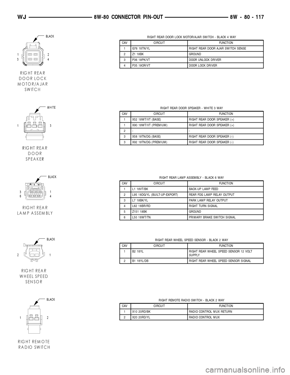
RIGHT REAR DOOR LOCK MOTOR/AJAR SWITCH - BLACK 4 WAY
CAV CIRCUIT FUNCTION
1 G76 18TN/YL RIGHT REAR DOOR AJAR SWITCH SENSE
2 Z1 18BK GROUND
3 P36 18PK/VT DOOR UNLOCK DRIVER
4 P35 18OR/VT DOOR LOCK DRIVER
RIGHT REAR DOOR SPEAKER - WHITE 3 WAY
CAV CIRCUIT FUNCTION
1 X52 18WT/VT (BASE) RIGHT REAR DOOR SPEAKER (+)
1 X90 18WT/VT (PREMIUM) RIGHT REAR DOOR SPEAKER (+)
2- -
3 X58 18TN/DG (BASE) RIGHT REAR DOOR SPEAKER (-)
3 X92 18TN/DG (PREMIUM) RIGHT REAR DOOR SPEAKER (-)
RIGHT REAR LAMP ASSEMBLY - BLACK 6 WAY
CAV CIRCUIT FUNCTION
1 L1 18VT/BK BACK-UP LAMP FEED
2 L95 18DG/YL (BUILT-UP-EXPORT) REAR FOG LAMP RELAY OUTPUT
3 L7 18BK/YL PARK LAMP RELAY OUTPUT
4 L62 18BR/RD RIGHT TURN SIGNAL
5 Z151 18BK GROUND
6 L50 18WT/TN PRIMARY BRAKE SWITCH SIGNAL
RIGHT REAR WHEEL SPEED SENSOR - BLACK 2 WAY
CAV CIRCUIT FUNCTION
1 B2 18YL RIGHT REAR WHEEL SPEED SENSOR 12 VOLT
SUPPLY
2 B1 18YL/DB RIGHT REAR WHEEL SPEED SENSOR SIGNAL
RIGHT REMOTE RADIO SWITCH - BLACK 2 WAY
CAV CIRCUIT FUNCTION
1 X10 20RD/BK RADIO CONTROL MUX RETURN
2 X20 20RD/YL RADIO CONTROL MUX
WJ8W-80 CONNECTOR PIN-OUT 8W - 80 - 117
Page 1179 of 2199
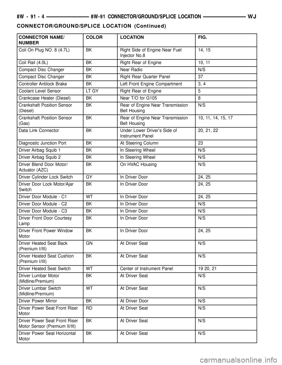
CONNECTOR NAME/
NUMBERCOLOR LOCATION FIG.
Coil On Plug NO. 8 (4.7L) BK Right Side of Engine Near Fuel
Injector No.814, 15
Coil Rail (4.0L) BK Right Rear of Engine 10, 11
Compact Disc Changer BK Near Radio N/S
Compact Disc Changer BK Right Rear Quarter Panel 37
Controller Antilock Brake BK Left Front Engine Compartment 3, 4
Coolant Level Sensor LT GY Right Rear of Engine 5
Crankcase Heater (Diesel) BK Near T/O for G105 8
Crankshaft Position Sensor
(Diesel)BK Rear of Engine Near Transmission
Bell HousingN/S
Crankshaft Position Sensor
(Gas)BK Rear of Engine Near Transmission
Bell Housing10, 11, 14, 15, 17
Data Link Connector BK Under Lower Driver's Side of
Instrument Panel20, 21, 22
Diagnostic Junction Port BK At Steering Column 23
Driver Airbag Squib 1 BK In Steering Wheel N/S
Driver Airbag Squib 2 BK In Steering Wheel N/S
Driver Blend Door Motor/
Actuator (AZC)BK On HVAC Housing N/S
Driver Cylinder Lock Switch GY In Driver Door 24, 25
Driver Door Lock Motor/Ajar
SwitchBK In Driver Door 24, 25
Driver Door Module - C1 WT In Driver Door 24, 25
Driver Door Module - C2 BK In Driver Door N/S
Driver Door Module - C3 BK In Driver Door N/S
Driver Front Door Courtesy
LampBK In Driver Door N/S
Driver Front Power Window
MotorBK In Driver Door 24, 25
Driver Heated Seat Back
(Premium I/III)GN At Driver Seat N/S
Driver Heated Seat Cushion
(Premium I/III)BK At Driver Seat N/S
Driver Heated Seat Switch WT Center of Instrument Panel 19 20, 21
Driver Lumbar Motor
(Midline/Premium)BK At Driver Seat N/S
Driver Lumbar Switch
(Midline/Premium)WT At Driver Seat N/S
Driver Power Mirror BK At Driver Door N/S
Driver Power Seat Front Riser
MotorRD At Driver Seat N/S
Driver Power Seat Front Riser
Motor Sensor (Premium II/III)BK At Driver Seat N/S
Driver Power Seat Horizontal
MotorBK At Driver Seat N/S
8W - 91 - 4 8W-91 CONNECTOR/GROUND/SPLICE LOCATIONWJ
CONNECTOR/GROUND/SPLICE LOCATION (Continued)
Page 1182 of 2199
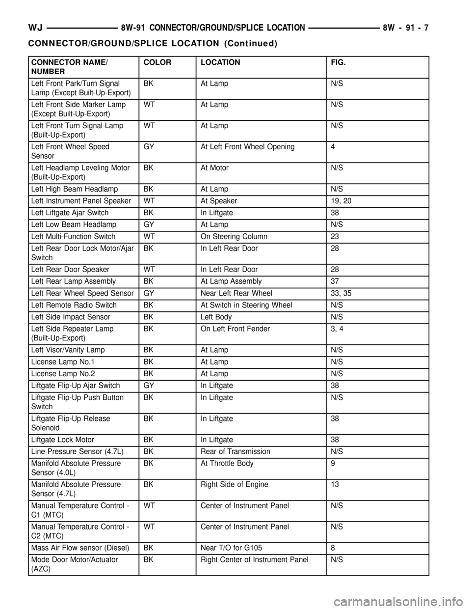
CONNECTOR NAME/
NUMBERCOLOR LOCATION FIG.
Left Front Park/Turn Signal
Lamp (Except Built-Up-Export)BK At Lamp N/S
Left Front Side Marker Lamp
(Except Built-Up-Export)WT At Lamp N/S
Left Front Turn Signal Lamp
(Built-Up-Export)WT At Lamp N/S
Left Front Wheel Speed
SensorGY At Left Front Wheel Opening 4
Left Headlamp Leveling Motor
(Built-Up-Export)BK At Motor N/S
Left High Beam Headlamp BK At Lamp N/S
Left Instrument Panel Speaker WT At Speaker 19, 20
Left Liftgate Ajar Switch BK In Liftgate 38
Left Low Beam Headlamp GY At Lamp N/S
Left Multi-Function Switch WT On Steering Column 23
Left Rear Door Lock Motor/Ajar
SwitchBK In Left Rear Door 28
Left Rear Door Speaker WT In Left Rear Door 28
Left Rear Lamp Assembly BK At Lamp Assembly 37
Left Rear Wheel Speed Sensor GY Near Left Rear Wheel 33, 35
Left Remote Radio Switch BK At Switch in Steering Wheel N/S
Left Side Impact Sensor BK Left Body N/S
Left Side Repeater Lamp
(Built-Up-Export)BK On Left Front Fender 3, 4
Left Visor/Vanity Lamp BK At Lamp N/S
License Lamp No.1 BK At Lamp N/S
License Lamp No.2 BK At Lamp N/S
Liftgate Flip-Up Ajar Switch GY In Liftgate 38
Liftgate Flip-Up Push Button
SwitchBK In Liftgate N/S
Liftgate Flip-Up Release
SolenoidBK In Liftgate 38
Liftgate Lock Motor BK In Liftgate 38
Line Pressure Sensor (4.7L) BK Rear of Transmission N/S
Manifold Absolute Pressure
Sensor (4.0L)BK At Throttle Body 9
Manifold Absolute Pressure
Sensor (4.7L)BK Right Side of Engine 13
Manual Temperature Control -
C1 (MTC)WT Center of Instrument Panel N/S
Manual Temperature Control -
C2 (MTC)WT Center of Instrument Panel N/S
Mass Air Flow sensor (Diesel) BK Near T/O for G105 8
Mode Door Motor/Actuator
(AZC)BK Right Center of Instrument Panel N/S
WJ8W-91 CONNECTOR/GROUND/SPLICE LOCATION 8W - 91 - 7
CONNECTOR/GROUND/SPLICE LOCATION (Continued)
Page 1184 of 2199
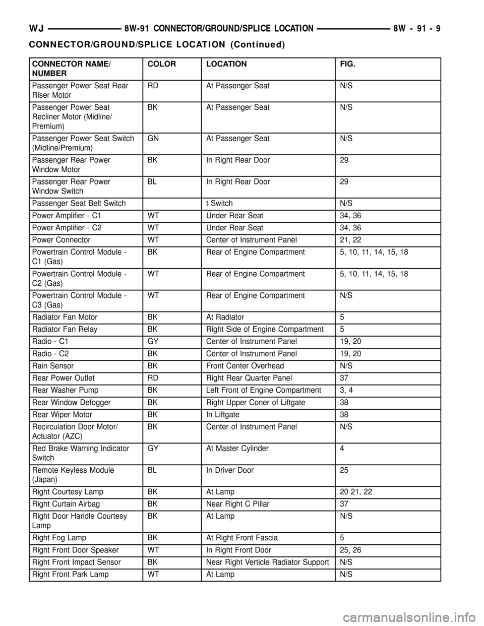
CONNECTOR NAME/
NUMBERCOLOR LOCATION FIG.
Passenger Power Seat Rear
Riser MotorRD At Passenger Seat N/S
Passenger Power Seat
Recliner Motor (Midline/
Premium)BK At Passenger Seat N/S
Passenger Power Seat Switch
(Midline/Premium)GN At Passenger Seat N/S
Passenger Rear Power
Window MotorBK In Right Rear Door 29
Passenger Rear Power
Window SwitchBL In Right Rear Door 29
Passenger Seat Belt Switch t Switch N/S
Power Amplifier - C1 WT Under Rear Seat 34, 36
Power Amplifier - C2 WT Under Rear Seat 34, 36
Power Connector WT Center of Instrument Panel 21, 22
Powertrain Control Module -
C1 (Gas)BK Rear of Engine Compartment 5, 10, 11, 14, 15, 18
Powertrain Control Module -
C2 (Gas)WT Rear of Engine Compartment 5, 10, 11, 14, 15, 18
Powertrain Control Module -
C3 (Gas)WT Rear of Engine Compartment N/S
Radiator Fan Motor BK At Radiator 5
Radiator Fan Relay BK Right Side of Engine Compartment 5
Radio - C1 GY Center of Instrument Panel 19, 20
Radio - C2 BK Center of Instrument Panel 19, 20
Rain Sensor BK Front Center Overhead N/S
Rear Power Outlet RD Right Rear Quarter Panel 37
Rear Washer Pump BK Left Front of Engine Compartment 3, 4
Rear Window Defogger BK Right Upper Coner of Liftgate 38
Rear Wiper Motor BK In Liftgate 38
Recirculation Door Motor/
Actuator (AZC)BK Center of Instrument Panel N/S
Red Brake Warning Indicator
SwitchGY At Master Cylinder 4
Remote Keyless Module
(Japan)BL In Driver Door 25
Right Courtesy Lamp BK At Lamp 20 21, 22
Right Curtain Airbag BK Near Right C Pillar 37
Right Door Handle Courtesy
LampBK At Lamp N/S
Right Fog Lamp BK At Right Front Fascia 5
Right Front Door Speaker WT In Right Front Door 25, 26
Right Front Impact Sensor BK Near Right Verticle Radiator Support N/S
Right Front Park Lamp WT At Lamp N/S
WJ8W-91 CONNECTOR/GROUND/SPLICE LOCATION 8W - 91 - 9
CONNECTOR/GROUND/SPLICE LOCATION (Continued)
Page 1185 of 2199
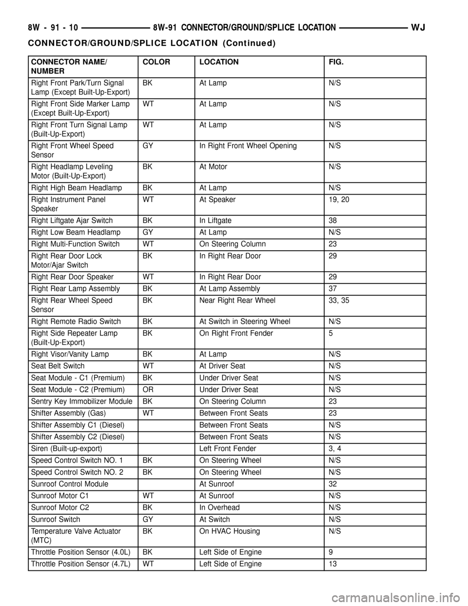
CONNECTOR NAME/
NUMBERCOLOR LOCATION FIG.
Right Front Park/Turn Signal
Lamp (Except Built-Up-Export)BK At Lamp N/S
Right Front Side Marker Lamp
(Except Built-Up-Export)WT At Lamp N/S
Right Front Turn Signal Lamp
(Built-Up-Export)WT At Lamp N/S
Right Front Wheel Speed
SensorGY In Right Front Wheel Opening N/S
Right Headlamp Leveling
Motor (Built-Up-Export)BK At Motor N/S
Right High Beam Headlamp BK At Lamp N/S
Right Instrument Panel
SpeakerWT At Speaker 19, 20
Right Liftgate Ajar Switch BK In Liftgate 38
Right Low Beam Headlamp GY At Lamp N/S
Right Multi-Function Switch WT On Steering Column 23
Right Rear Door Lock
Motor/Ajar SwitchBK In Right Rear Door 29
Right Rear Door Speaker WT In Right Rear Door 29
Right Rear Lamp Assembly BK At Lamp Assembly 37
Right Rear Wheel Speed
SensorBK Near Right Rear Wheel 33, 35
Right Remote Radio Switch BK At Switch in Steering Wheel N/S
Right Side Repeater Lamp
(Built-Up-Export)BK On Right Front Fender 5
Right Visor/Vanity Lamp BK At Lamp N/S
Seat Belt Switch WT At Driver Seat N/S
Seat Module - C1 (Premium) BK Under Driver Seat N/S
Seat Module - C2 (Premium) OR Under Driver Seat N/S
Sentry Key Immobilizer Module BK On Steering Column 23
Shifter Assembly (Gas) WT Between Front Seats 23
Shifter Assembly C1 (Diesel) Between Front Seats N/S
Shifter Assembly C2 (Diesel) Between Front Seats N/S
Siren (Built-up-export) Left Front Fender 3, 4
Speed Control Switch NO. 1 BK On Steering Wheel N/S
Speed Control Switch NO. 2 BK On Steering Wheel N/S
Sunroof Control Module At Sunroof 32
Sunroof Motor C1 WT At Sunroof N/S
Sunroof Motor C2 BK In Overhead N/S
Sunroof Switch GY At Switch N/S
Temperature Valve Actuator
(MTC)BK On HVAC Housing N/S
Throttle Position Sensor (4.0L) BK Left Side of Engine 9
Throttle Position Sensor (4.7L) WT Left Side of Engine 13
8W - 91 - 10 8W-91 CONNECTOR/GROUND/SPLICE LOCATIONWJ
CONNECTOR/GROUND/SPLICE LOCATION (Continued)
Page 1189 of 2199
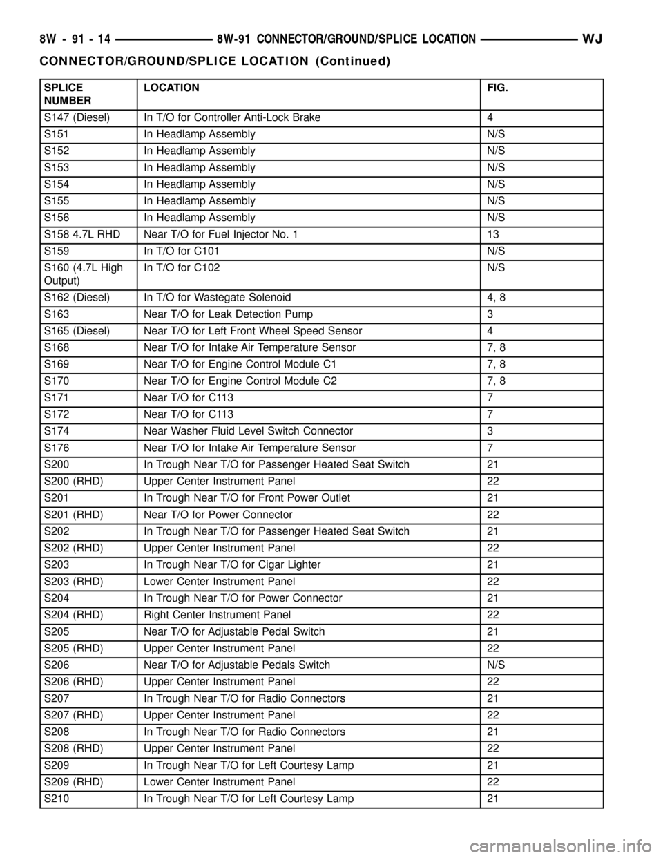
SPLICE
NUMBERLOCATION FIG.
S147 (Diesel) In T/O for Controller Anti-Lock Brake 4
S151 In Headlamp Assembly N/S
S152 In Headlamp Assembly N/S
S153 In Headlamp Assembly N/S
S154 In Headlamp Assembly N/S
S155 In Headlamp Assembly N/S
S156 In Headlamp Assembly N/S
S158 4.7L RHD Near T/O for Fuel Injector No. 1 13
S159 In T/O for C101 N/S
S160 (4.7L High
Output)In T/O for C102 N/S
S162 (Diesel) In T/O for Wastegate Solenoid 4, 8
S163 Near T/O for Leak Detection Pump 3
S165 (Diesel) Near T/O for Left Front Wheel Speed Sensor 4
S168 Near T/O for Intake Air Temperature Sensor 7, 8
S169 Near T/O for Engine Control Module C1 7, 8
S170 Near T/O for Engine Control Module C2 7, 8
S171 Near T/O for C113 7
S172 Near T/O for C113 7
S174 Near Washer Fluid Level Switch Connector 3
S176 Near T/O for Intake Air Temperature Sensor 7
S200 In Trough Near T/O for Passenger Heated Seat Switch 21
S200 (RHD) Upper Center Instrument Panel 22
S201 In Trough Near T/O for Front Power Outlet 21
S201 (RHD) Near T/O for Power Connector 22
S202 In Trough Near T/O for Passenger Heated Seat Switch 21
S202 (RHD) Upper Center Instrument Panel 22
S203 In Trough Near T/O for Cigar Lighter 21
S203 (RHD) Lower Center Instrument Panel 22
S204 In Trough Near T/O for Power Connector 21
S204 (RHD) Right Center Instrument Panel 22
S205 Near T/O for Adjustable Pedal Switch 21
S205 (RHD) Upper Center Instrument Panel 22
S206 Near T/O for Adjustable Pedals Switch N/S
S206 (RHD) Upper Center Instrument Panel 22
S207 In Trough Near T/O for Radio Connectors 21
S207 (RHD) Upper Center Instrument Panel 22
S208 In Trough Near T/O for Radio Connectors 21
S208 (RHD) Upper Center Instrument Panel 22
S209 In Trough Near T/O for Left Courtesy Lamp 21
S209 (RHD) Lower Center Instrument Panel 22
S210 In Trough Near T/O for Left Courtesy Lamp 21
8W - 91 - 14 8W-91 CONNECTOR/GROUND/SPLICE LOCATIONWJ
CONNECTOR/GROUND/SPLICE LOCATION (Continued)
Page 1190 of 2199
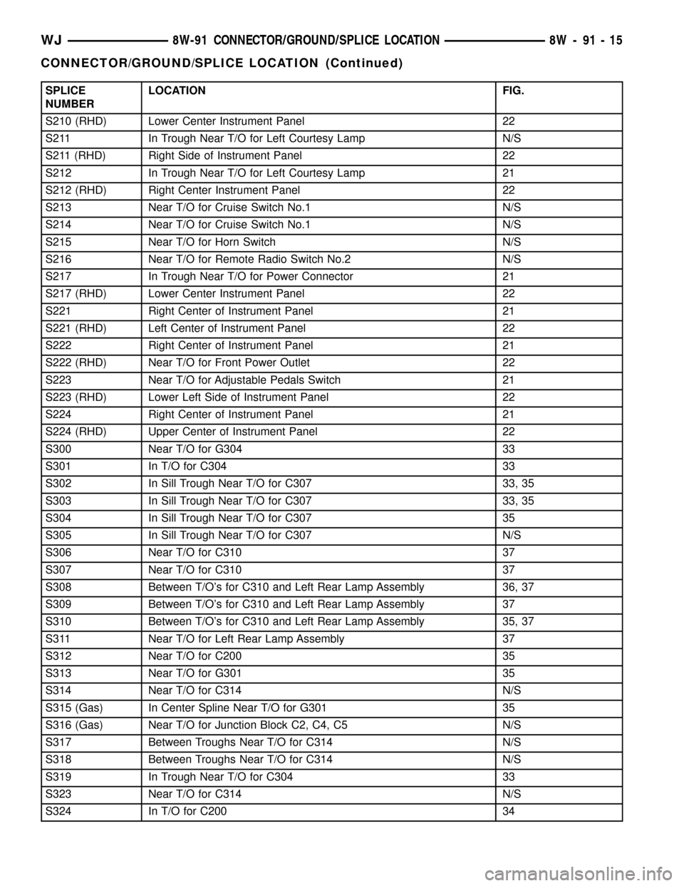
SPLICE
NUMBERLOCATION FIG.
S210 (RHD) Lower Center Instrument Panel 22
S211 In Trough Near T/O for Left Courtesy Lamp N/S
S211 (RHD) Right Side of Instrument Panel 22
S212 In Trough Near T/O for Left Courtesy Lamp 21
S212 (RHD) Right Center Instrument Panel 22
S213 Near T/O for Cruise Switch No.1 N/S
S214 Near T/O for Cruise Switch No.1 N/S
S215 Near T/O for Horn Switch N/S
S216 Near T/O for Remote Radio Switch No.2 N/S
S217 In Trough Near T/O for Power Connector 21
S217 (RHD) Lower Center Instrument Panel 22
S221 Right Center of Instrument Panel 21
S221 (RHD) Left Center of Instrument Panel 22
S222 Right Center of Instrument Panel 21
S222 (RHD) Near T/O for Front Power Outlet 22
S223 Near T/O for Adjustable Pedals Switch 21
S223 (RHD) Lower Left Side of Instrument Panel 22
S224 Right Center of Instrument Panel 21
S224 (RHD) Upper Center of Instrument Panel 22
S300 Near T/O for G304 33
S301 In T/O for C304 33
S302 In Sill Trough Near T/O for C307 33, 35
S303 In Sill Trough Near T/O for C307 33, 35
S304 In Sill Trough Near T/O for C307 35
S305 In Sill Trough Near T/O for C307 N/S
S306 Near T/O for C310 37
S307 Near T/O for C310 37
S308 Between T/O's for C310 and Left Rear Lamp Assembly 36, 37
S309 Between T/O's for C310 and Left Rear Lamp Assembly 37
S310 Between T/O's for C310 and Left Rear Lamp Assembly 35, 37
S311 Near T/O for Left Rear Lamp Assembly 37
S312 Near T/O for C200 35
S313 Near T/O for G301 35
S314 Near T/O for C314 N/S
S315 (Gas) In Center Spline Near T/O for G301 35
S316 (Gas) Near T/O for Junction Block C2, C4, C5 N/S
S317 Between Troughs Near T/O for C314 N/S
S318 Between Troughs Near T/O for C314 N/S
S319 In Trough Near T/O for C304 33
S323 Near T/O for C314 N/S
S324 In T/O for C200 34
WJ8W-91 CONNECTOR/GROUND/SPLICE LOCATION 8W - 91 - 15
CONNECTOR/GROUND/SPLICE LOCATION (Continued)
Page 1380 of 2199

(6) Remove accessory drive belt (Refer to 7 -
COOLING/ACCESSORY DRIVE/DRIVE BELTS -
REMOVAL).
(7) Disconnect generator electrical connections.
(8) Unbolt the generator and move it away from
the intake manifold for clearance.
(9) Disconnect air conditioning compressor electri-
cal connections.
(10) Unbolt the air conditioning compressor and
move it away from the intake manifold for clearance.
(11) Disconnect left and right radio suppressor
straps.
(12) Disconnect and remove ignition coil towers
(Refer to 8 - ELECTRICAL/IGNITION CONTROL/
IGNITION COIL - REMOVAL).
(13) Remove top oil dipstick tube retaining bolt
and ground strap.
(14) Bleed pressure from fuel system (Refer to 14 -
FUEL SYSTEM/FUEL DELIVERY - STANDARD
PROCEDURE).
(15) Remove fuel rail (Refer to 14 - FUEL SYS-
TEM/FUEL DELIVERY/FUEL RAIL - REMOVAL).
(16) Remove throttle body assembly and mounting
bracket.
(17) Drain cooling system below coolant tempera-
ture level (Refer to 7 - COOLING - STANDARD
PROCEDURE).
(18) Remove coolant temperature sensor (Refer to
7 - COOLING/ENGINE/ENGINE COOLANT TEMP
SENSOR - REMOVAL).
(19) Remove cowl to hood seal. (Refer to 23 -
BODY/WEATHERSTRIP/SEALS/COWL WEATHER-
STRIP - REMOVAL).
(20) Remove right side engine lifting stud.
(21) Remove intake manifold retaining fasteners,
in reverse order of tightening sequence (Fig. 105).
NOTE: Intake must be lifted upward and level in the
front and rear to clear the cowl. Interference with
the cowl will occur during removal.
(22) Remove intake manifold.
CLEANING
NOTE: There is NO approved repair procedure for
the intake manifold. If severe damage is found dur-
ing inspection, the intake manifold must be
replaced.
Before installing the intake manifold thoroughly
clean the mating surfaces. Use a suitable cleaning
solvent, then air dry.
INSPECTION
(1) Inspect the intake sealing surface for cracks,
nicks and distortion.(2) Inspect the intake manifold vacuum hose fit-
tings for looseness or blockage.
(3) Inspect the manifold to throttle body mating
surface for cracks, nicks and distortion.
INSTALLATION
(1) Install intake manifold gaskets.
(2) Install intake manifold.
(3) Install intake manifold retaining bolts and
tighten in sequence shown in (Fig. 106) to 12 N´m
(105 in. lbs.).
(4) Install left and right radio suppressor straps.
(5) Install throttle body assembly.
(6) Install throttle cable bracket.
Fig. 105 Intake Manifold Tightening Sequence
Fig. 106 Intake Manifold Tightening Sequence
WJENGINE - 4.7L 9 - 137
INTAKE MANIFOLD (Continued)
Page 1871 of 2199
TIRE PRESSURE MONITORING
DESCRIPTION
The EVIC will monitor the tire pressure signals
from the five tire sensors and determine if any tire
has gone below the low pressure threshold or raised
above the high pressure threshold. Refer to the table
below.
LOW TIRE PRESSURE THRESHOLDS
SYSTEM STATUS
INDICATORTIRE PRESSURE
ON 179 kPa (26 PSI)
OFF 214 kPa (31 PSI)
HIGH TIRE PRESSURE THRESHOLDS
SYSTEM STATUS
INDICATORTIRE PRESSURE
ON 310 kPa (45 PSI)
OFF 276 kPa (40 PSI)
The Remote Tire Pressure Monitors (RTPM) are
not internally serviceable. For a Sensor Failure or
Low Battery fault, the RTPM must be replaced.
OPERATION
If equipped with the Tire Pressure Monitoring Sys-
tem, each of the vehicle's five wheels will have a
valve stem with a pressure sensor and radio trans-
mitter built in. Signals from the tire pressure sensors
are received and interpreted by the Electronic Vehi-
cle Information Center (EVIC). A sensor in a
mounted wheel will broadcast its detected pressure
once per minute when the vehicle is moving faster
than 40 km/h (25 mph). The spare tire sensor will
broadcast once every hour. Each sensor's broadcast is
uniquely coded so that the EVIC can determine loca-
tion. The individual tire pressures can be displayed
graphically on the EVIC
DIAGNOSIS AND TESTING - TIRE PRESSURE
MONITORING SYSTEM
All Tire Pressure Monitoring System Faults are
specific to one location. If a9BATTERY LOW9or
9SENSOR FAILURE9fault is detected, the location
will be displayed. The appropriate sensor/transmitter
can then be replaced. If a single sensor/transmitter
cannot be detected by the EVIC, replace that sensor
transmitter. If none of the sensors/transmitters can
be detected, refer to symptoms in the EVIC section.
For additional system description and diagnosis,
refer to Tire Pressure Monitoring in the Body Diag-
nostic manual.
SENSOR
REMOVAL - TIRE PRESSURE SENSOR/
TRANSMITTER
(1) Remove the tire/wheel from the vehicle.
CAUTION: When removing the stick on balancing
weights from the wheel, do not use an abrasive
cleaner or a cleaner which will damage the protec-
tive finish on the wheel.
(2) Remove the balancing weights from the wheel.
NOTE: The cap used on this valve stem contains an
O-ring seal to prevent contamination and moisture
from entering the valve stem. Retain this valve stem
cap for re-use. Do not substitute a regular valve
stem cap in its place.
(3) Remove the cap from the valve stem.
NOTE: The valve stem used on this vehicle is made
of aluminum and the core is nickel plated brass.
The original valve stem core must be reinstalled
and not substituted for a valve stem core made of a
different material. This is required to prevent corro-
sion in the valve stem caused by the different met-
als.
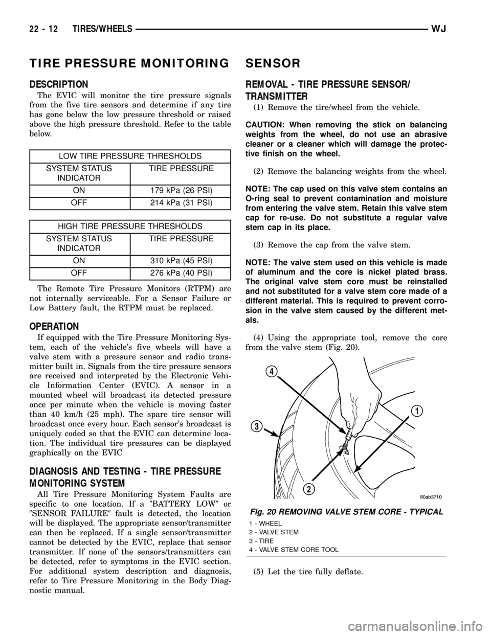
(4) Using the appropriate tool, remove the core
from the valve stem (Fig. 20).
(5) Let the tire fully deflate.
Fig. 20 REMOVING VALVE STEM CORE - TYPICAL
1 - WHEEL
2 - VALVE STEM
3 - TIRE
4 - VALVE STEM CORE TOOL
22 - 12 TIRES/WHEELSWJ
Page 1902 of 2199
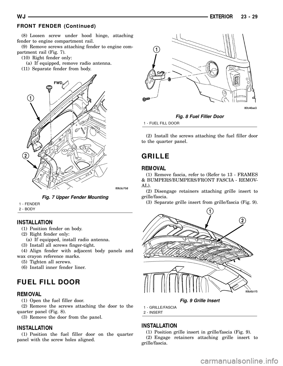
(8) Loosen screw under hood hinge, attaching
fender to engine compartment rail.
(9) Remove screws attaching fender to engine com-
partment rail (Fig. 7).
(10) Right fender only:
(a) If equipped, remove radio antenna.
(11) Separate fender from body.
INSTALLATION
(1) Position fender on body.
(2) Right fender only:
(a) If equipped, install radio antenna.
(3) Install all screws finger-tight.
(4) Align fender with adjacent body panels and
wax crayon reference marks.
(5) Tighten all screws.
(6) Install inner fender liner.
FUEL FILL DOOR
REMOVAL
(1) Open the fuel filler door.
(2) Remove the screws attaching the door to the
quarter panel (Fig. 8).
(3) Remove the door from the panel.
INSTALLATION
(1) Position the fuel filler door on the quarter
panel with the screw holes aligned.(2) Install the screws attaching the fuel filler door
to the quarter panel.
GRILLE
REMOVAL
(1) Remove fascia, refer to (Refer to 13 - FRAMES
& BUMPERS/BUMPERS/FRONT FASCIA - REMOV-
AL).
(2) Disengage retainers attaching grille insert to
grille/fascia.
(3) Separate grille insert from grille/fascia (Fig. 9).
INSTALLATION
(1) Position grille insert in grille/fascia (Fig. 9).
(2) Engage retainers attaching grille insert to
grille/fascia.
Fig. 7 Upper Fender Mounting
1 - FENDER
2 - BODY
Fig. 8 Fuel Filler Door
1 - FUEL FILL DOOR
Fig. 9 Grille Insert
1 - GRILLE/FASCIA
2 - INSERT
WJEXTERIOR 23 - 29
FRONT FENDER (Continued)