Transfer JEEP GRAND CHEROKEE 2002 WJ / 2.G Repair Manual
[x] Cancel search | Manufacturer: JEEP, Model Year: 2002, Model line: GRAND CHEROKEE, Model: JEEP GRAND CHEROKEE 2002 WJ / 2.GPages: 2199, PDF Size: 76.01 MB
Page 1393 of 2199

body. Install Special Tool 8514 lock pin into hole on
front of tensioner. Slowly open vise to transfer piston
spring force to lock pin (Fig. 128).
(2) Position primary chain tensioner over oil pump
and insert bolts into lower two holes on tensioner
bracket. Tighten bolts to 28 N´m (250 in. lbs.).
CAUTION: Overtightening the tensioner arm torxT
bolt can cause severe damage to the cylinder head.
Tighten torxTbolt to specified torque only.
(3) Install right side chain tensioner arm. Apply
MopartLock N, Seal to torxtbolt, tighten bolt to 17
N´m (150 in. lbs.).
NOTE: The silver bolts retain the guides to the cyl-
inder heads and the black bolts retain the guides to
the engine block.(4) Install the left side chain guide. Tighten the
bolts to 28 N´m (250 in. lbs.).
CAUTION: Overtightening the tensioner arm torxT
bolt can cause severe damage to the cylinder head.
Tighten torxTbolt to specified torque only.
(5) Install left side chain tensioner arm. Apply
MopartLock N, Seal to torxtbolt, tighten bolt to 17
N´m (150 in. lbs.).
(6) Install the right side chain guide. Tighten the
bolts to 28 N´m (250 in. lbs.).
(7) Install both secondary chains onto the idler
sprocket. Align two plated links on the secondary
chains to be visible through the two lower openings
on the idler sprocket (4 o'clock and 8 o'clock). Once
the secondary timing chains are installed, position
special tool 8515 to hold chains in place for installa-
tion (Fig. 129).
Fig. 127 Timing Chain System
1 - RIGHT CAMSHAFT SPROCKET AND SECONDARY CHAIN
2 - SECONDARY TIMING CHAIN TENSIONER (LEFT AND RIGHT
SIDE NOT COMMON)
3 - SECONDARY TENSIONER ARM
4 - LEFT CAMSHAFT SPROCKET AND SECONDARY CHAIN
5 - CHAIN GUIDE
6 - TWO PLATED LINKS ON RIGHT CAMSHAFT CHAIN7 - PRIMARY CHAIN
8 - IDLER SPROCKET
9 - CRANKSHAFT SPROCKET
10 - PRIMARY CHAIN TENSIONER
11 - TWO PLATED LINKS ON LEFT CAMSHAFT CHAIN
12 - SECONDARY TENSIONER ARM
9 - 150 ENGINE - 4.7LWJ
TIMING BELT/CHAIN AND SPROCKETS (Continued)
Page 1412 of 2199
FRAME & BUMPERS
TABLE OF CONTENTS
page page
FRONT ABSORBER
REMOVAL.............................1
INSTALLATION..........................1
FRONT FASCIA
REMOVAL.............................1
INSTALLATION..........................1
REAR ABSORBER
REMOVAL.............................2
INSTALLATION..........................2
REAR FASCIA
REMOVAL.............................2
INSTALLATION..........................4
FRAME
SPECIFICATIONS
SPECIFICATIONS - TORQUE.............4
FRAME DIMENSIONS...................4
FRONT SKID PLATE
REMOVAL.............................7INSTALLATION..........................7
FRONT TOW HOOK
REMOVAL.............................7
INSTALLATION..........................7
FUEL TANK SKID PLATE
DESCRIPTION..........................7
REAR TOW HOOK
REMOVAL.............................7
INSTALLATION..........................7
TRAILER HITCH
REMOVAL.............................8
INSTALLATION..........................8
TRANSFER CASE SKID PLATE
REMOVAL.............................8
INSTALLATION..........................8
FRONT ABSORBER
REMOVAL
(1) Remove front fascia, refer to (Refer to 13 -
FRAMES & BUMPERS/BUMPERS/FRONT FASCIA
- REMOVAL).
(2) Remove the retainer attaching the absorber to
the fascia.
(3) Separate the absorber from the fascia.
INSTALLATION
(1) Position the absorber on the fascia.
(2) Install the retainer attaching the absorber to
the fascia.
(3) Install front fascia. Refer to (Refer to 13 -
FRAMES & BUMPERS/BUMPERS/FRONT FASCIA
- INSTALLATION).
FRONT FASCIA
REMOVAL
(1) Raise and support vehicle.
(2) Turn front wheels to access rivets and remove
plastic rivets attaching fascia to wheel liner.
(3) Remove bolts attaching fascia to fender (Fig. 1).(4) Remove plastic push pin fasteners attaching
front fascia to lower radiator crossmember splash
shield (Fig. 2).
(5) Disengage fog lamp connectors, if equipped.
(6) Remove screws attaching fascia/grille to upper
radiator crossmember (Fig. 3).
(7) Slide fascia forward to separate from vehicle.
INSTALLATION
(1) Slide fascia onto vehicle engaging fascia with
tabs on bottom of front fenders.
(2) Install screws attaching fascia/grille to upper
radiator crossmember (Fig. 3).
(3) Install bolts attaching fascia to fender (Fig. 1).
(4) Engage fog lamp connectors, if equipped.
(5) Install plastic rivets attaching fascia to wheel
liner.
(6) Install plastic push pin fasteners attaching
front fascia to lower radiator crossmember splash
shield (Fig. 2).
(7) Remove supports and lower vehicle.
WJFRAME & BUMPERS 13 - 1
Page 1415 of 2199
INSTALLATION
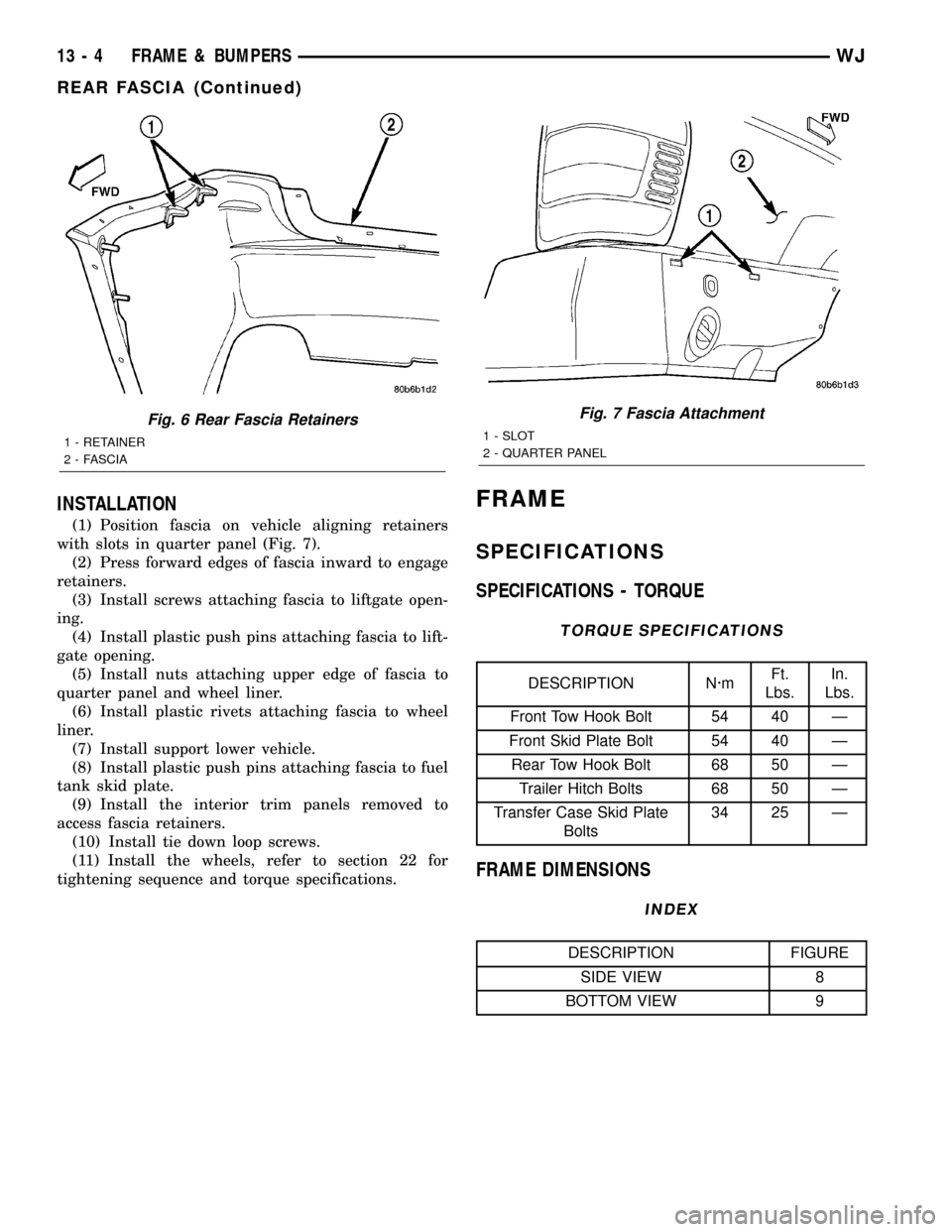
(1) Position fascia on vehicle aligning retainers
with slots in quarter panel (Fig. 7).
(2) Press forward edges of fascia inward to engage
retainers.
(3) Install screws attaching fascia to liftgate open-
ing.
(4) Install plastic push pins attaching fascia to lift-
gate opening.
(5) Install nuts attaching upper edge of fascia to
quarter panel and wheel liner.
(6) Install plastic rivets attaching fascia to wheel
liner.
(7) Install support lower vehicle.
(8) Install plastic push pins attaching fascia to fuel
tank skid plate.
(9) Install the interior trim panels removed to
access fascia retainers.
(10) Install tie down loop screws.
(11) Install the wheels, refer to section 22 for
tightening sequence and torque specifications.
FRAME
SPECIFICATIONS
SPECIFICATIONS - TORQUE
TORQUE SPECIFICATIONS
DESCRIPTION N´mFt.
Lbs.In.
Lbs.
Front Tow Hook Bolt 54 40 Ð
Front Skid Plate Bolt 54 40 Ð
Rear Tow Hook Bolt 68 50 Ð
Trailer Hitch Bolts 68 50 Ð
Transfer Case Skid Plate
Bolts34 25 Ð
FRAME DIMENSIONS
INDEX
DESCRIPTION FIGURE
SIDE VIEW 8
BOTTOM VIEW 9
Fig. 6 Rear Fascia Retainers
1 - RETAINER
2 - FASCIA
Fig. 7 Fascia Attachment
1 - SLOT
2 - QUARTER PANEL
13 - 4 FRAME & BUMPERSWJ
REAR FASCIA (Continued)
Page 1419 of 2199
TRAILER HITCH
REMOVAL
(1) Remove rear fascia, refer to (Refer to 13 -
FRAMES & BUMPERS/BUMPERS/REAR FASCIA -
REMOVAL).
(2) Remove screws attaching trailer harness plug
to trailer hitch.
(3) Disconnect harness connector from harness
plug.
(4) Position support stands under trailer hitch.
(5) Remove bolts attaching trailer hitch to frame
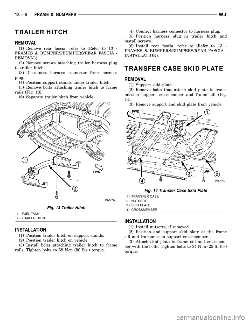
rails (Fig. 13).
(6) Separate trailer hitch from vehicle.
INSTALLATION
(1) Position trailer hitch on support stands.
(2) Position trailer hitch on vehicle.
(3) Install bolts attaching trailer hitch to frame
rails. Tighten bolts to 68 N´m (50 lbs.) torque.(4) Connect harness connector to harness plug.
(5) Position harness plug in trailer hitch and
install screws.
(6) Install rear fascia, refer to (Refer to 13 -
FRAMES & BUMPERS/BUMPERS/REAR FASCIA -
INSTALLATION).
TRANSFER CASE SKID PLATE
REMOVAL
(1) Support skid plate.
(2) Remove bolts that attach skid plate to trans-
mission support crossmember and frame sill (Fig.
14).
(3) Remove support and skid plate from vehicle.
INSTALLATION
(1) Install nutserts, if removed.
(2) Position and support skid plate at the frame
sill and transmission support crossmember.
(3) Attach skid plate to frame sill and crossmem-
ber with the bolts. Tighten bolts to 34 N´m (25 ft. lbs)
torque.
Fig. 13 Trailer Hitch
1 - FUEL TANK
2 - TRAILER HITCH
Fig. 14 Transfer Case Skid Plate
1 - TRANSFER CASE
2 - NUTSERT
3 - SKID PLATE
4 - CROSSMEMBER
13 - 8 FRAME & BUMPERSWJ
Page 1506 of 2199
INSTALLATION
(1) Install the steering damper to the axle bracket
and tie rod.
(2) Install the steering damper bolt in the axle
bracket and tighten bolt to 88 N´m (65 ft. lbs.).
(3) Install the nut at the tie rod and tighten to 41
N´m (30 ft. lbs.).
DRAG LINK
DESCRIPTION
The drag link and ends are comprised of two forged
ends connected by a steel adjusting tube. The drag
link connects the steering gear pitman arm to the
steering knuckle. The larger offset end is attached to
the pitman arm.
OPERATION
The sleeve is used for steering wheel centering.
REMOVAL
(1) Raise and support the vehicle.
(2) Remove right wheel and tire assembly.
(3) Remove the cotter pins and nuts at the right
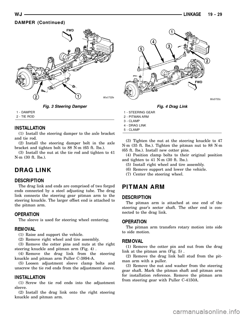
steering knuckle and pitman arm (Fig. 4) .
(4) Remove the drag link from the steering
knuckle and pitman arm Puller C-3894-A.
(5) Loosen adjustment sleeve clamp bolts and
unscrew the tie rod ends from the adjustment sleeve.
INSTALLATION
(1) Screw the tie rod ends into the adjustment
sleeve.
(2) Install the drag link onto the right steering
knuckle and pitman arm.(3) Tighten the nut at the steering knuckle to 47
N´m (35 ft. lbs.). Tighten the pitman nut to 88 N´m
(65 ft. lbs.). Install new cotter pins.
(4) Position clamp bolts to their original position
and tighten to 41 N´m (30 ft. lbs.).
(5) Install right wheel and tire assembly.
(6) Remove support and lower the vehicle.
(7) Center the steering wheel.
PITMAN ARM
DESCRIPTION
The pitman arm is attached at one end of the
steering gear's sector shaft. The other end is con-
nected to the drag link.
OPERATION
The pitman arm transfers rotary motion into side
to side motion.
REMOVAL
(1) Remove the cotter pin and nut from the drag
link at the pitman arm (Fig. 5) .
(2) Remove the drag link ball stud from the pit-
man arm with a puller.
(3) Remove the nut and washer from the steering
gear shaft. Mark the pitman shaft and pitman arm
for installation reference. Remove the pitman arm
from steering gear with Puller C-4150A.
Fig. 3 Steering Damper
1 - DAMPER
2 - TIE ROD
Fig. 4 Drag Link
1 - STEERING GEAR
2 - PITMAN ARM
3 - CLAMP
4 - DRAG LINK
5 - CLAMP
WJLINKAGE 19 - 29
DAMPER (Continued)
Page 1507 of 2199
INSTALLATION
(1) Align and install the pitman arm on steering
gear shaft.
(2) Install the washer and nut on the shaft and
tighten the nut to 251 N´m (185 ft. lbs.).
(3) Install drag link ball stud to pitman arm.
Install nut and tighten to 88 N´m (65 ft. lbs.). Install
a new cotter pin.
TIE ROD END
DESCRIPTION
The ends are forged, with a lubed for life ball
socket.
OPERATION
The tie rod ends connect the drag link to the wheel
assembly. The tie rod provides toe alignment and
transfers steering input from the drag link to the
wheels.
REMOVAL
(1) Raise and support the vehicle.
(2) Remove wheel and tire assemblies.
(3) Remove the damper nut from the tie rod clamp
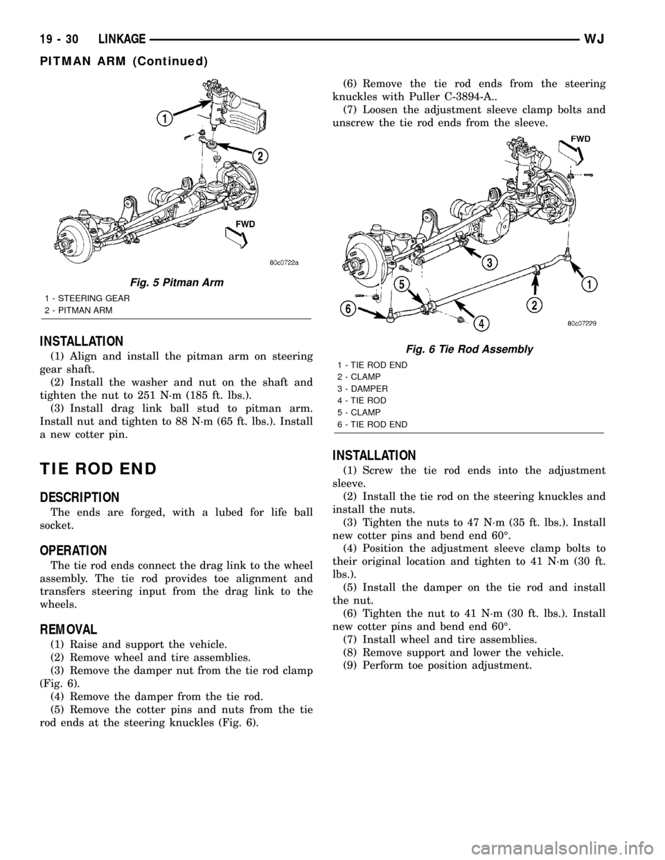
(Fig. 6).
(4) Remove the damper from the tie rod.
(5) Remove the cotter pins and nuts from the tie
rod ends at the steering knuckles (Fig. 6).(6) Remove the tie rod ends from the steering
knuckles with Puller C-3894-A..
(7) Loosen the adjustment sleeve clamp bolts and
unscrew the tie rod ends from the sleeve.
INSTALLATION
(1) Screw the tie rod ends into the adjustment
sleeve.
(2) Install the tie rod on the steering knuckles and
install the nuts.
(3) Tighten the nuts to 47 N´m (35 ft. lbs.). Install
new cotter pins and bend end 60É.
(4) Position the adjustment sleeve clamp bolts to
their original location and tighten to 41 N´m (30 ft.
lbs.).
(5) Install the damper on the tie rod and install
the nut.
(6) Tighten the nut to 41 N´m (30 ft. lbs.). Install
new cotter pins and bend end 60É.
(7) Install wheel and tire assemblies.
(8) Remove support and lower the vehicle.
(9) Perform toe position adjustment.
Fig. 5 Pitman Arm
1 - STEERING GEAR
2 - PITMAN ARM
Fig. 6 Tie Rod Assembly
1 - TIE ROD END
2 - CLAMP
3 - DAMPER
4 - TIE ROD
5 - CLAMP
6 - TIE ROD END
19 - 30 LINKAGEWJ
PITMAN ARM (Continued)
Page 1514 of 2199
INSTALLATION
(1) Position and install the power steering cooler
to the vehicle.
(2) Install the three mounting bracket bolts (Fig.
6).
(3) Reconnect the upper hose at cooler (Fig. 6).
(4) Reconnect the lower hose at cooler (Fig. 6).
(5) Connect negative battery cable to battery.
(6) Refill the power steering fluid and bleed the
system,(Refer to 19 - STEERING/PUMP - STAN-
DARD PROCEDURE).
(7) Start engine and check for leaks.
(8) Install the grille opening reinforcement panel
(9) Install the front fascia grille,(Refer to 13 -
FRAMES & BUMPERS/BUMPERS/FRONT FASCIA
- INSTALLATION).
HOSES - 4.0L
DESCRIPTION
DESCRIPTION - PRESSURE LINE
The hose consists of two metal ends and rubber
center section that contains a tuning cable. The
pump end uses a quick connect fitting. Lubircation
must be used on the quick connect nut and o-ring
when installing.
DESCRIPTION - RETURN LINE
Power steering return line is a hose which is
clamped at the pump and the gear.
OPERATION
OPERATION - PRESSURE LINE
Power steering pressure line, is used to transfer
high pressure power steering fluid, from the power
steering pump to the power steering gear on the
4.0L. The 4.7L power steering pressure line, is used
to transfer high pressure power steering fluid, from
the power steering pump to the engine cooling fan
and the steering gear.
OPERATION - RETURN LINE
Power steering return line, is used to transfer low
pressure power steering fluid, from the power steer-
ing gear to the power steering pump.
REMOVAL
(1) Drain the power steering fluid from the reser-
voir.
(2) Remove the air box,(Refer to 9 - ENGINE/AIR
INTAKE SYSTEM/AIR CLEANER HOUSING -
REMOVAL).
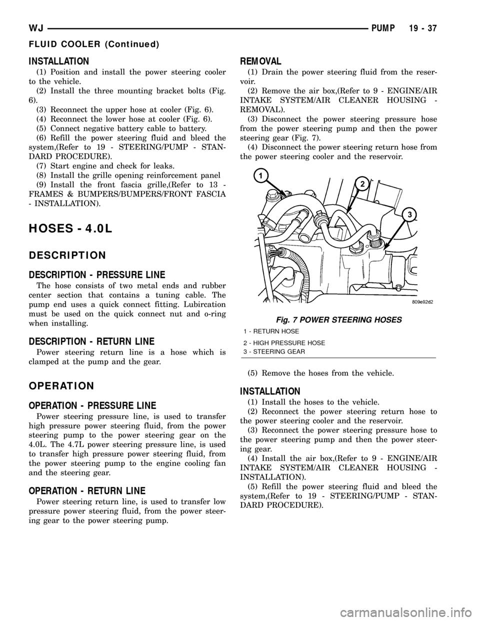
(3) Disconnect the power steering pressure hose
from the power steering pump and then the power
steering gear (Fig. 7).
(4) Disconnect the power steering return hose from
the power steering cooler and the reservoir.
(5) Remove the hoses from the vehicle.
INSTALLATION
(1) Install the hoses to the vehicle.
(2) Reconnect the power steering return hose to
the power steering cooler and the reservoir.
(3) Reconnect the power steering pressure hose to
the power steering pump and then the power steer-
ing gear.
(4) Install the air box,(Refer to 9 - ENGINE/AIR
INTAKE SYSTEM/AIR CLEANER HOUSING -
INSTALLATION).
(5) Refill the power steering fluid and bleed the
system,(Refer to 19 - STEERING/PUMP - STAN-
DARD PROCEDURE).
Fig. 7 POWER STEERING HOSES
1 - RETURN HOSE
2 - HIGH PRESSURE HOSE
3 - STEERING GEAR
WJPUMP 19 - 37
FLUID COOLER (Continued)
Page 1515 of 2199
HOSES - 4.7L
DESCRIPTION
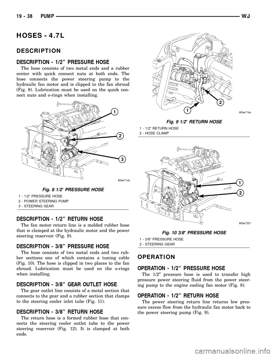
DESCRIPTION - 1/2º PRESSURE HOSE
The hose consists of two metal ends and a rubber
center with quick connect nuts at both ends. The
hose connects the power steering pump to the
hydraulic fan motor and is clipped to the fan shroud
(Fig. 8). Lubrication must be used on the quick con-
nect nuts and o-rings when installing.
DESCRIPTION - 1/2º RETURN HOSE
The fan motor return line is a molded rubber hose
that is clamped at the hydraulic motor and the power
steering reservoir (Fig. 9).
DESCRIPTION - 3/8º PRESSURE HOSE
The hose consists of two metal ends and two rub-
ber sections one of which contains a tuning cable
(Fig. 10). The hose is clipped in two places to the fan
shroud. Lubrication must be used on the o-rings
when installing.
DESCRIPTION - 3/8º GEAR OUTLET HOSE
The gear outlet line consists of a metal section that
connects to the gear and a rubber section that clamps
to the steering cooler inlet tube (Fig. 11).
DESCRIPTION - 3/8º RETURN HOSE
The return hose is a formed rubber hose that con-
nects the steering cooler outlet tube to the power
steering reservoir (Fig. 12). It is clamped at both
ends.
OPERATION
OPERATION - 1/2º PRESSURE HOSE
The 1/2º pressure hose is used to transfer high
pressure power steering fluid from the power steer-
ing pump to the engine cooling fan motor (Fig. 8).
OPERATION - 1/2º RETURN HOSE
The power steering return line returns low pres-
sure excess flow from the hydraulic fan motor back to
the power steering pump (Fig. 9).
Fig. 8 1/2(PRESSURE HOSE
1 - 1/29PRESSURE HOSE
2 - POWER STEERING PUMP
3 - STEERING GEAR
Fig. 9 1/2(RETURN HOSE
1 - 1/29RETURN HOSE
2 - HOSE CLAMP
Fig. 10 3/8(PRESSURE HOSE
1 - 3/89PRESSURE HOSE
2 - STEERING GEAR
19 - 38 PUMPWJ
Page 1520 of 2199
TRANSMISSION AND TRANSFER CASE
TABLE OF CONTENTS
page page
AUTOMATIC TRANSMISSION - 42RE..........1
AUTOMATIC TRANSMISSION - 545RFE......177TRANSFER CASE - NV242................280
TRANSFER CASE - NV247................315
AUTOMATIC TRANSMISSION - 42RE
TABLE OF CONTENTS
page page
AUTOMATIC TRANSMISSION - 42RE
DESCRIPTION..........................3
OPERATION............................5
DIAGNOSIS AND TESTING
DIAGNOSIS AND TESTING - AUTOMATIC
TRANSMISSION......................11
DIAGNOSIS AND TESTING - PRELIMINARY . 11
DIAGNOSIS AND TESTING - ROAD
TESTING............................11
DIAGNOSIS AND TESTING - HYDRAULIC
PRESSURE TEST.....................12
DIAGNOSIS AND TESTING - AIR CHECKING
TRANSMISSION CLUTCH AND BAND
OPERATION.........................15
DIAGNOSIS AND TESTING - CONVERTER
HOUSING FLUID LEAK.................15
DIAGNOSIS AND TESTING - DIAGNOSIS
CHARTS............................16
STANDARD PROCEDURE - ALUMINUM
THREAD REPAIR......................26
REMOVAL.............................27
DISASSEMBLY.........................29
CLEANING............................34
INSPECTION..........................34
ASSEMBLY............................34
INSTALLATION.........................41
SCHEMATICS AND DIAGRAMS
HYDRAULIC SCHEMATICS..............43
SPECIFICATIONS
TRANSMISSION......................55
SPECIAL TOOLS
RE TRANSMISSIONS..................57
ACCUMULATOR
DESCRIPTION.........................60
OPERATION...........................60
INSPECTION..........................60BANDS
DESCRIPTION.........................61
OPERATION...........................61
ADJUSTMENTS
ADJUSTMENT - BANDS................62
BRAKE TRANSMISSION SHIFT INTERLOCK
MECHANISM
DESCRIPTION.........................63
OPERATION...........................63
DIAGNOSIS AND TESTING - BRAKE
TRANSMISSION SHIFT INTERLOCK.......63
ADJUSTMENTS - BRAKE TRANSMISSION
SHIFT INTERLOCK....................64
ELECTRONIC GOVERNOR
DESCRIPTION.........................65
OPERATION...........................65
REMOVAL.............................67
INSTALLATION.........................67
EXTENSION HOUSING BUSHING
REMOVAL.............................68
INSTALLATION.........................68
EXTENSION HOUSING SEAL
REMOVAL.............................69
INSTALLATION.........................69
FLUID AND FILTER
DIAGNOSIS AND TESTING
DIAGNOSIS AND TESTING - EFFECTS OF
INCORRECT FLUID LEVEL..............69
DIAGNOSIS AND TESTING - CAUSES OF
BURNT FLUID........................69
DIAGNOSIS AND TESTING - FLUID
CONTAMINATION.....................70
STANDARD PROCEDURE
STANDARD PROCEDURE - FLUID LEVEL
CHECK.............................70
WJTRANSMISSION AND TRANSFER CASE 21 - 1
Page 1522 of 2199

STANDARD PROCEDURE - TORQUE
CONVERTER DRAINBACK VALVE........134
TRANSMISSION TEMPERATURE SENSOR
DESCRIPTION........................134
OPERATION..........................134
VALVE BODY
DESCRIPTION........................135
OPERATION..........................139REMOVAL............................154
DISASSEMBLY........................155
CLEANING...........................165
INSPECTION.........................166
ASSEMBLY...........................167
INSTALLATION........................175
ADJUSTMENTS - VALVE BODY...........175
AUTOMATIC TRANSMISSION -
42RE
DESCRIPTION
The 42RE is a four speed fully automatic transmis-
sion (Fig. 1) with an electronic governor. The 42RE is
equipped with a lock-up clutch in the torque con-
verter. First through third gear ranges are provided
by the clutches, bands, overrunning clutch, and plan-
etary gear sets in the transmission. Fourth gear
range is provided by the overdrive unit that contains
an overdrive clutch, direct clutch, planetary gear set,
and overrunning clutch.The transmission contains a front, rear, and direct
clutch which function as the input driving compo-
nents. It also contains the kickdown (front) and the
low/reverse (rear) bands which, along with the over-
running clutch and overdrive clutch, serve as the
holding components. The driving and holding compo-
nents combine to select the necessary planetary gear
components, in the front, rear, or overdrive planetary
gear set, transfer the engine power from the input
shaft through to the output shaft.
The valve body is mounted to the lower side of the
transmission and contains the valves to control pres-
sure regulation, fluid flow control, and clutch/band
application. The oil pump is mounted at the front of
the transmission and is driven by the torque con-
verter hub. The pump supplies the oil pressure nec-
essary for clutch/band actuation and transmission
lubrication.
WJAUTOMATIC TRANSMISSION - 42RE 21 - 3