Crank case JEEP GRAND CHEROKEE 2002 WJ / 2.G Workshop Manual
[x] Cancel search | Manufacturer: JEEP, Model Year: 2002, Model line: GRAND CHEROKEE, Model: JEEP GRAND CHEROKEE 2002 WJ / 2.GPages: 2199, PDF Size: 76.01 MB
Page 260 of 2199

The same thermostat is used for winter and sum-
mer seasons. An engine should not be operated with-
out a thermostat, except for servicing or testing.
Operating without a thermostat causes other prob-
lems. These are: longer engine warmup time, unreli-
able warmup performance, increased exhaust
emissions and crankcase condensation. This conden-
sation can result in sludge formation.
DESCRIPTIONÐ4.0L ENGINE
CAUTION: Do not operate an engine without a ther-
mostat, except for servicing or testing.
A pellet-type thermostat controls the operating
temperature of the engine by controlling the amount
of coolant flow to the radiator. On all engines the
thermostat is closed below 195ÉF (90ÉC). Above this
temperature, coolant is allowed to flow to the radia-
tor. This provides quick engine warm up and overall
temperature control. (Fig. 23).
The same thermostat is used for winter and sum-
mer seasons. An engine should not be operated with-out a thermostat, except for servicing or testing.
Operating without a thermostat causes other prob-
lems. These are: longer engine warmup time, unreli-
able warmup performance, increased exhaust
emissions and crankcase condensation. This conden-
sation can result in sludge formation.
OPERATION
The wax pellet is located in a sealed container at
the spring end of the thermostat. When heated, the
pellet expands, overcoming closing spring tension
and water pump pressure to force the valve to open.
DIAGNOSIS AND TESTINGÐTHERMOSTAT
ON-BOARD DIAGNOSTICS
All models are equipped with On-Board Diagnos-
tics for certain cooling system components.If the pow-
ertrain control module (PCM) detects low engine
coolant temperature, it will record a Diagnostic Trou-
ble Code (DTC). For other DTC numbers, (Refer to 25
- EMISSIONS CONTROL - DESCRIPTION).
The DTC can also be accessed through the DRB
scan tool.
Fig. 22 Thermostat
1 - FROM HEATER
2 - FROM RADIATOR
3 - TO WATER PUMP
4 - ENGINE BYPASS
5 - THERMOSTAT
Fig. 23 Thermostat and Housing
1 - LONG BOLT
2 - GASKET
3 - THERMOSTAT
4 - THERMOSTAT HOUSING
5 - SHORT BOLT
WJENGINE 7 - 37
ENGINE COOLANT THERMOSTAT (Continued)
Page 334 of 2199
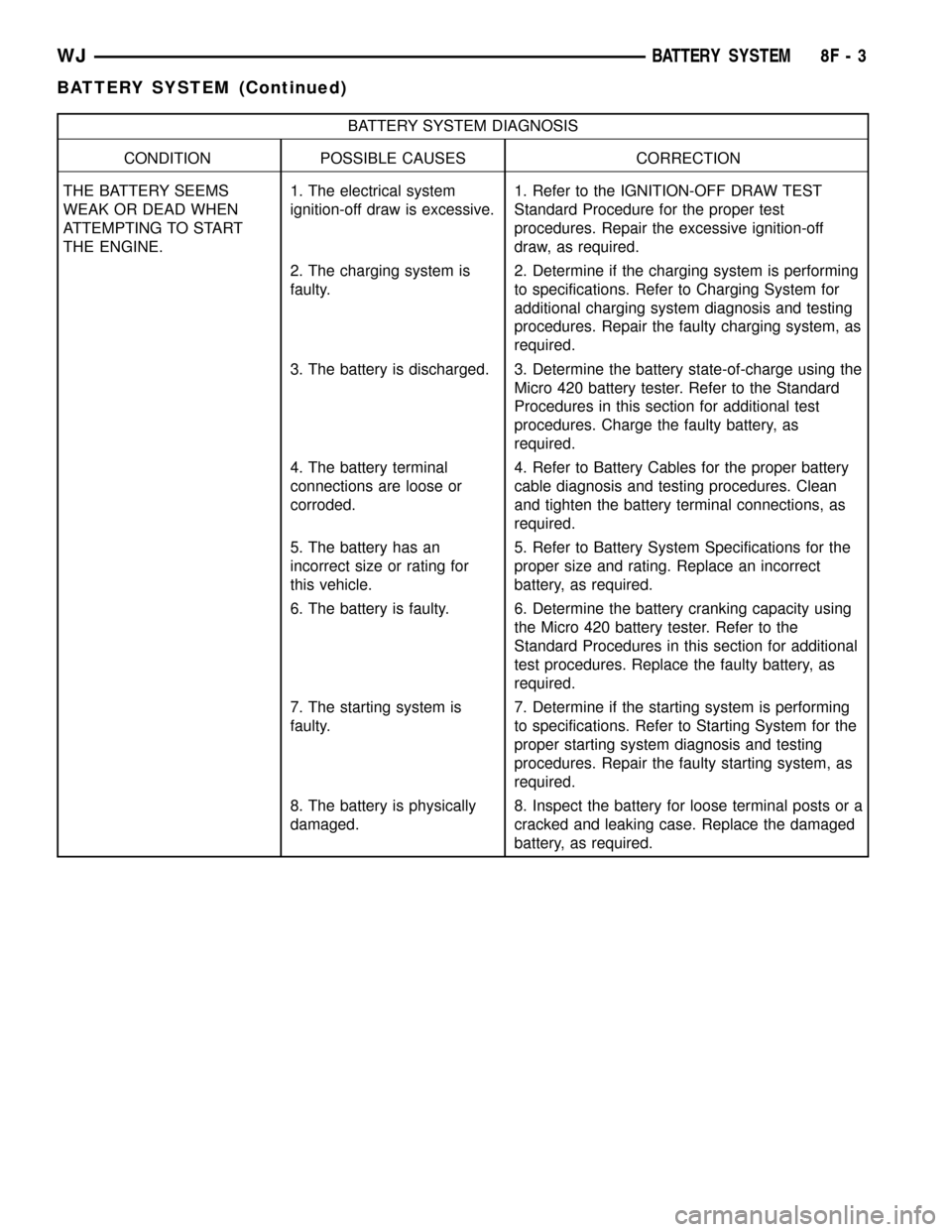
BATTERY SYSTEM DIAGNOSIS
CONDITION POSSIBLE CAUSES CORRECTION
THE BATTERY SEEMS
WEAK OR DEAD WHEN
ATTEMPTING TO START
THE ENGINE.1. The electrical system
ignition-off draw is excessive.1. Refer to the IGNITION-OFF DRAW TEST
Standard Procedure for the proper test
procedures. Repair the excessive ignition-off
draw, as required.
2. The charging system is
faulty.2. Determine if the charging system is performing
to specifications. Refer to Charging System for
additional charging system diagnosis and testing
procedures. Repair the faulty charging system, as
required.
3. The battery is discharged. 3. Determine the battery state-of-charge using the
Micro 420 battery tester. Refer to the Standard
Procedures in this section for additional test
procedures. Charge the faulty battery, as
required.
4. The battery terminal
connections are loose or
corroded.4. Refer to Battery Cables for the proper battery
cable diagnosis and testing procedures. Clean
and tighten the battery terminal connections, as
required.
5. The battery has an
incorrect size or rating for
this vehicle.5. Refer to Battery System Specifications for the
proper size and rating. Replace an incorrect
battery, as required.
6. The battery is faulty. 6. Determine the battery cranking capacity using
the Micro 420 battery tester. Refer to the
Standard Procedures in this section for additional
test procedures. Replace the faulty battery, as
required.
7. The starting system is
faulty.7. Determine if the starting system is performing
to specifications. Refer to Starting System for the
proper starting system diagnosis and testing
procedures. Repair the faulty starting system, as
required.
8. The battery is physically
damaged.8. Inspect the battery for loose terminal posts or a
cracked and leaking case. Replace the damaged
battery, as required.
WJBATTERY SYSTEM 8F - 3
BATTERY SYSTEM (Continued)
Page 337 of 2199
INSPECTION
The following information details the recommended
inspection procedures for the battery and related
components. In addition to the maintenance sched-
ules found in this service manual and the owner's
manual, it is recommended that these procedures be
performed any time the battery or related compo-
nents must be removed for vehicle service.
(1) Inspect the battery cable terminal clamps for
damage. Replace any battery cable that has a dam-
aged or deformed terminal clamp.
(2) Inspect the battery tray and battery holddown
hardware for damage. Replace any damaged parts.
(3) Slide the thermal guard off of the battery case.
Inspect the battery case for cracks or other damage
that could result in electrolyte leaks. Also, check the
battery terminal posts for looseness. Batteries with
damaged cases or loose terminal posts must be
replaced.
(4) Inspect the battery built-in test indicator sight
glass for an indication of the battery condition. If the
battery is discharged, charge as required. Refer to
Standard Procedures for the proper battery built-in
indicator test procedures. Also refer to Standard Pro-
cedures for the proper battery charging procedures.
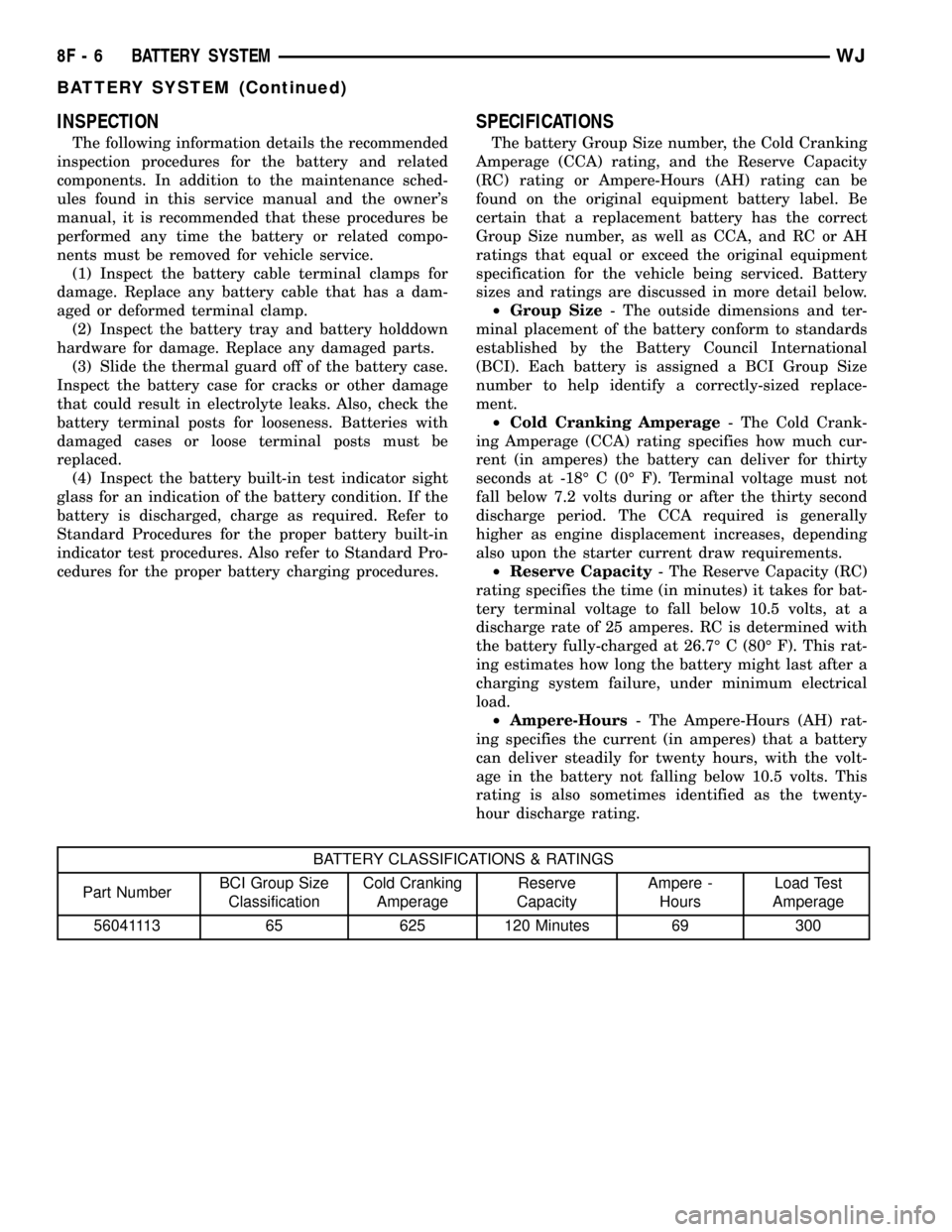
SPECIFICATIONS
The battery Group Size number, the Cold Cranking
Amperage (CCA) rating, and the Reserve Capacity
(RC) rating or Ampere-Hours (AH) rating can be
found on the original equipment battery label. Be
certain that a replacement battery has the correct
Group Size number, as well as CCA, and RC or AH
ratings that equal or exceed the original equipment
specification for the vehicle being serviced. Battery
sizes and ratings are discussed in more detail below.
²Group Size- The outside dimensions and ter-
minal placement of the battery conform to standards
established by the Battery Council International
(BCI). Each battery is assigned a BCI Group Size
number to help identify a correctly-sized replace-
ment.
²Cold Cranking Amperage- The Cold Crank-
ing Amperage (CCA) rating specifies how much cur-
rent (in amperes) the battery can deliver for thirty
seconds at -18É C (0É F). Terminal voltage must not
fall below 7.2 volts during or after the thirty second
discharge period. The CCA required is generally
higher as engine displacement increases, depending
also upon the starter current draw requirements.
²Reserve Capacity- The Reserve Capacity (RC)
rating specifies the time (in minutes) it takes for bat-
tery terminal voltage to fall below 10.5 volts, at a
discharge rate of 25 amperes. RC is determined with
the battery fully-charged at 26.7É C (80É F). This rat-
ing estimates how long the battery might last after a
charging system failure, under minimum electrical
load.
²Ampere-Hours- The Ampere-Hours (AH) rat-
ing specifies the current (in amperes) that a battery
can deliver steadily for twenty hours, with the volt-
age in the battery not falling below 10.5 volts. This
rating is also sometimes identified as the twenty-
hour discharge rating.
BATTERY CLASSIFICATIONS & RATINGS
Part NumberBCI Group Size
ClassificationCold Cranking
AmperageReserve
CapacityAmpere -
HoursLoad Test
Amperage
56041113 65 625 120 Minutes 69 300
8F - 6 BATTERY SYSTEMWJ
BATTERY SYSTEM (Continued)
Page 340 of 2199

to determine its cranking capacity. A battery that is
fully-charged, but does not pass the load test, is
faulty and must be replaced.
NOTE: Completely discharged batteries may take
several hours to accept a charge. Refer to Standard
Procedures for the proper battery charging proce-
dures.
STANDARD PROCEDURE
STANDARD PROCEDURE - BATTERY
CHARGING
Battery charging is the means by which the bat-
tery can be restored to its full voltage potential. A
battery is fully-charged when:
²Micro 420 electrical system tester indicates bat-
tery is OK.
²All of the battery cells are gassing freely during
battery charging.
²Three hydrometer tests, taken at one-hour inter-
vals, indicate no increase in the temperature-cor-
rected specific gravity of the battery electrolyte.
²Open-circuit voltage of the battery is 12.4 volts
or above.
WARNING: NEVER EXCEED TWENTY AMPERES
WHEN CHARGING A COLD (-1É C [30É F] OR
LOWER) BATTERY. THE BATTERY MAY ARC INTER-
NALLY AND EXPLODE. PERSONAL INJURY AND/OR
VEHICLE DAMAGE MAY RESULT.
WARNING: IF THE BATTERY SHOWS SIGNS OF
FREEZING, LEAKING, LOOSE POSTS, DO NOT
TEST, ASSIST-BOOST, OR CHARGE. THE BATTERY
MAY ARC INTERNALLY AND EXPLODE. PERSONAL
INJURY AND/OR VEHICLE DAMAGE MAY RESULT.
WARNING: EXPLOSIVE HYDROGEN GAS FORMS IN
AND AROUND THE BATTERY. DO NOT SMOKE,
USE FLAME, OR CREATE SPARKS NEAR THE BAT-
TERY. PERSONAL INJURY AND/OR VEHICLE DAM-
AGE MAY RESULT.
WARNING: THE BATTERY CONTAINS SULFURIC
ACID, WHICH IS POISONOUS AND CAUSTIC. AVOID
CONTACT WITH THE SKIN, EYES, OR CLOTHING.
IN THE EVENT OF CONTACT, FLUSH WITH WATER
AND CALL A PHYSICIAN IMMEDIATELY. KEEP OUT
OF THE REACH OF CHILDREN.WARNING: IF THE BATTERY IS EQUIPPED WITH
REMOVABLE CELL CAPS, BE CERTAIN THAT EACH
OF THE CELL CAPS IS IN PLACE AND TIGHT
BEFORE THE BATTERY IS RETURNED TO SER-
VICE. PERSONAL INJURY AND/OR VEHICLE DAM-
AGE MAY RESULT FROM LOOSE OR MISSING
CELL CAPS.
CAUTION: Always disconnect and isolate the bat-
tery negative cable before charging a battery. Do
not exceed sixteen volts while charging a battery.
Damage to the vehicle electrical system compo-
nents may result.
CAUTION: Battery electrolyte will bubble inside the
battery case during normal battery charging. Elec-
trolyte boiling or being discharged from the battery
vents indicates a battery overcharging condition.
Immediately reduce the charging rate or turn off the
charger to evaluate the battery condition. Damage
to the battery may result from overcharging.
CAUTION: The battery should not be hot to the
touch. If the battery feels hot to the touch, turn off
the charger and let the battery cool before continu-
ing the charging operation. Damage to the battery
may result.
After the battery has been charged to 12.4 volts or
greater, perform a load test to determine the battery
cranking capacity. Refer to Standard Procedures for
the proper battery load test procedures. If the battery
will endure a load test, return the battery to service.
If the battery will not endure a load test, it is faulty
and must be replaced.
Clean and inspect the battery hold downs, tray,
terminals, posts, and top before completing battery
service. Refer to Battery System Cleaning for the
proper battery system cleaning procedures, and Bat-
tery System Inspection for the proper battery system
inspection procedures.
CHARGING A COMPLETELY DISCHARGED
BATTERY
The following procedure should be used to recharge
a completely discharged battery. Unless this proce-
dure is properly followed, a good battery may be
needlessly replaced.
(1) Measure the voltage at the battery posts with a
voltmeter, accurate to 1/10 (0.10) volt (Fig. 5). If the
reading is below ten volts, the battery charging cur-
rent will be low. It could take some time before the
battery accepts a current greater than a few milliam-
peres. Such low current may not be detectable on the
ammeters built into many battery chargers.
WJBATTERY SYSTEM 8F - 9
BATTERY (Continued)
Page 342 of 2199
(2) If testing the battery IN-THE-VEHICLE, make
certain all of the vehicle accessory loads are OFF,
including the ignition.The preferred test position
is at the battery terminal. If the battery is not
accessible, you may test using both the positive and
negative jumper posts. Select TESTING AT JUMPER
POST when connecting to that location.
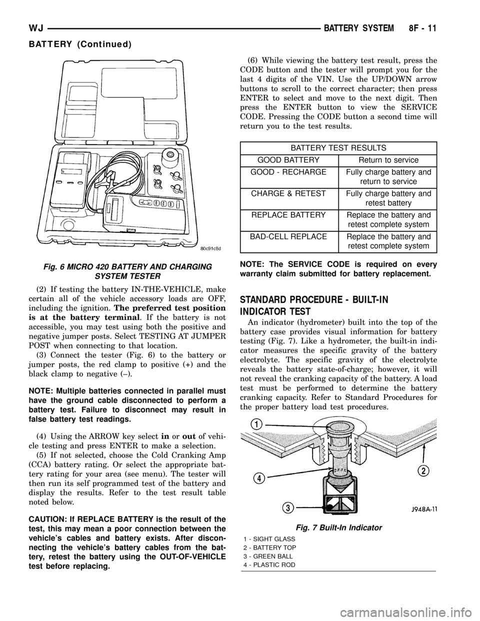
(3) Connect the tester (Fig. 6) to the battery or
jumper posts, the red clamp to positive (+) and the
black clamp to negative (±).
NOTE: Multiple batteries connected in parallel must
have the ground cable disconnected to perform a
battery test. Failure to disconnect may result in
false battery test readings.
(4) Using the ARROW key selectinoroutof vehi-
cle testing and press ENTER to make a selection.
(5) If not selected, choose the Cold Cranking Amp
(CCA) battery rating. Or select the appropriate bat-
tery rating for your area (see menu). The tester will
then run its self programmed test of the battery and
display the results. Refer to the test result table
noted below.
CAUTION: If REPLACE BATTERY is the result of the
test, this may mean a poor connection between the
vehicle's cables and battery exists. After discon-
necting the vehicle's battery cables from the bat-
tery, retest the battery using the OUT-OF-VEHICLE
test before replacing.(6) While viewing the battery test result, press the
CODE button and the tester will prompt you for the
last 4 digits of the VIN. Use the UP/DOWN arrow
buttons to scroll to the correct character; then press
ENTER to select and move to the next digit. Then
press the ENTER button to view the SERVICE
CODE. Pressing the CODE button a second time will
return you to the test results.
BATTERY TEST RESULTS
GOOD BATTERY Return to service
GOOD - RECHARGE Fully charge battery and
return to service
CHARGE & RETEST Fully charge battery and
retest battery
REPLACE BATTERY Replace the battery and
retest complete system
BAD-CELL REPLACE Replace the battery and
retest complete system
NOTE: The SERVICE CODE is required on every
warranty claim submitted for battery replacement.
STANDARD PROCEDURE - BUILT-IN
INDICATOR TEST
An indicator (hydrometer) built into the top of the
battery case provides visual information for battery
testing (Fig. 7). Like a hydrometer, the built-in indi-
cator measures the specific gravity of the battery
electrolyte. The specific gravity of the electrolyte
reveals the battery state-of-charge; however, it will
not reveal the cranking capacity of the battery. A load
test must be performed to determine the battery
cranking capacity. Refer to Standard Procedures for
the proper battery load test procedures.
Fig. 6 MICRO 420 BATTERY AND CHARGING
SYSTEM TESTER
Fig. 7 Built-In Indicator
1 - SIGHT GLASS
2 - BATTERY TOP
3 - GREEN BALL
4 - PLASTIC ROD
WJBATTERY SYSTEM 8F - 11
BATTERY (Continued)
Page 343 of 2199
Before testing, visually inspect the battery for any
damage (a cracked case or cover, loose posts, etc.)
that would cause the battery to be faulty. In order to
obtain correct indications from the built-in indicator,
it is important that the battery be level and have a
clean sight glass. Additional light may be required to
view the indicator.Do not use open flame as a
source of additional light.
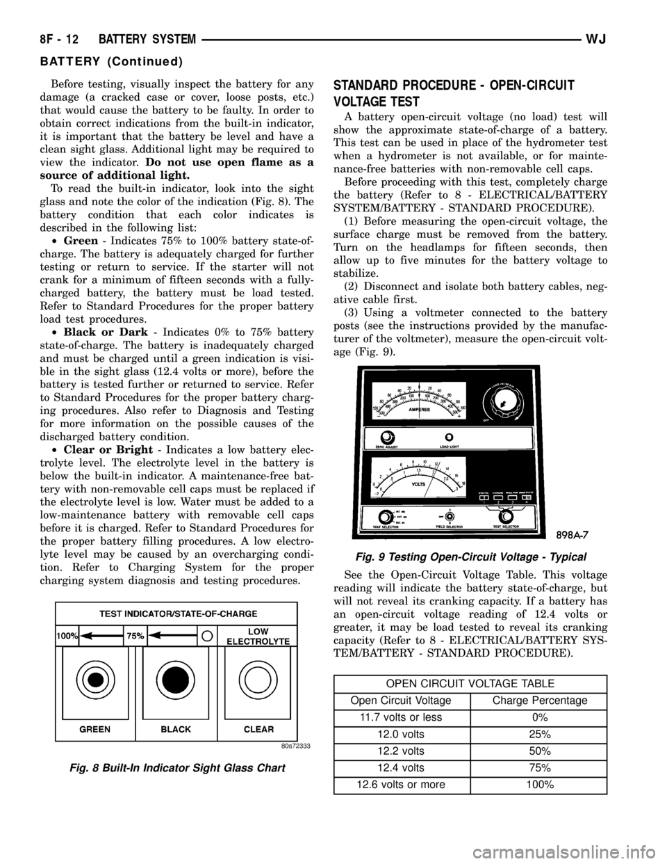
To read the built-in indicator, look into the sight
glass and note the color of the indication (Fig. 8). The
battery condition that each color indicates is
described in the following list:
²Green- Indicates 75% to 100% battery state-of-
charge. The battery is adequately charged for further
testing or return to service. If the starter will not
crank for a minimum of fifteen seconds with a fully-
charged battery, the battery must be load tested.
Refer to Standard Procedures for the proper battery
load test procedures.
²Black or Dark- Indicates 0% to 75% battery
state-of-charge. The battery is inadequately charged
and must be charged until a green indication is visi-
ble in the sight glass (12.4 volts or more), before the
battery is tested further or returned to service. Refer
to Standard Procedures for the proper battery charg-
ing procedures. Also refer to Diagnosis and Testing
for more information on the possible causes of the
discharged battery condition.
²Clear or Bright- Indicates a low battery elec-
trolyte level. The electrolyte level in the battery is
below the built-in indicator. A maintenance-free bat-
tery with non-removable cell caps must be replaced if
the electrolyte level is low. Water must be added to a
low-maintenance battery with removable cell caps
before it is charged. Refer to Standard Procedures for
the proper battery filling procedures. A low electro-
lyte level may be caused by an overcharging condi-
tion. Refer to Charging System for the proper
charging system diagnosis and testing procedures.STANDARD PROCEDURE - OPEN-CIRCUIT
VOLTAGE TEST
A battery open-circuit voltage (no load) test will
show the approximate state-of-charge of a battery.
This test can be used in place of the hydrometer test
when a hydrometer is not available, or for mainte-
nance-free batteries with non-removable cell caps.
Before proceeding with this test, completely charge
the battery (Refer to 8 - ELECTRICAL/BATTERY
SYSTEM/BATTERY - STANDARD PROCEDURE).
(1) Before measuring the open-circuit voltage, the
surface charge must be removed from the battery.
Turn on the headlamps for fifteen seconds, then
allow up to five minutes for the battery voltage to
stabilize.
(2) Disconnect and isolate both battery cables, neg-
ative cable first.
(3) Using a voltmeter connected to the battery
posts (see the instructions provided by the manufac-
turer of the voltmeter), measure the open-circuit volt-
age (Fig. 9).
See the Open-Circuit Voltage Table. This voltage
reading will indicate the battery state-of-charge, but
will not reveal its cranking capacity. If a battery has
an open-circuit voltage reading of 12.4 volts or
greater, it may be load tested to reveal its cranking
capacity (Refer to 8 - ELECTRICAL/BATTERY SYS-
TEM/BATTERY - STANDARD PROCEDURE).
OPEN CIRCUIT VOLTAGE TABLE
Open Circuit Voltage Charge Percentage
11.7 volts or less 0%
12.0 volts 25%
12.2 volts 50%
12.4 volts 75%
12.6 volts or more 100%
Fig. 8 Built-In Indicator Sight Glass Chart
Fig. 9 Testing Open-Circuit Voltage - Typical
8F - 12 BATTERY SYSTEMWJ
BATTERY (Continued)
Page 367 of 2199

OPERATION
These starter motors are equipped with a plane-
tary gear reduction (intermediate transmission) sys-
tem. The planetary gear reduction system consists of
a gear that is integral to the output end of the elec-
tric motor armature shaft that is in continual
engagement with a larger gear that is splined to the
input end of the starter pinion gear shaft. This fea-
ture makes it possible to reduce the dimensions of
the starter. At the same time, it allows higher arma-
ture rotational speed and delivers increased torque
through the starter pinion gear to the starter ring
gear.
The starter motors for both engines are activated
by an integral heavy duty starter solenoid switch
mounted to the overrunning clutch housing. This
electromechanical switch connects and disconnects
the feed of battery voltage to the starter motor and
actuates a shift fork that engages and disengages the
starter pinion gear with the starter ring gear.
Both starter motors use an overrunning clutch and
starter pinion gear unit to engage and drive a starter
ring gear that is integral to the torque converter
drive plate mounted on the rear crankshaft flange.
DIAGNOSIS AND TESTING - STARTER MOTOR
Correct starter motor operation can be confirmed
by performing the following free running bench test.
This test can only be performed with the starter
motor removed from the vehicle. Refer toStarting
Systemin the Specifications section of this group for
the starter motor specifications.
(1) Remove the starter motor from the vehicle.
Refer toStarter Motorin the Removal and Instal-
lation section of this group for the procedures.
(2) Mount the starter motor securely in a soft-
jawed bench vise. The vise jaws should be clamped
on the mounting flange of the starter motor. Never
clamp on the starter motor by the field frame.
(3) Connect a suitable volt-ampere tester and a
12-volt battery to the starter motor in series, and set
the ammeter to the 100 ampere scale. See the
instructions provided by the manufacturer of the
volt-ampere tester being used.
(4) Install a jumper wire from the solenoid termi-
nal to the solenoid battery terminal. The starter
motor should operate. If the starter motor fails to
operate, replace the faulty starter motor assembly.
(5) Adjust the carbon pile load of the tester to
obtain the free running test voltage. Refer toStart-
ing Systemin the Specifications section of this
group for the starter motor free running test voltage
specifications.
(6) Note the reading on the ammeter and compare
this reading to the free running test maximum
amperage draw. Refer toStarting Systemin theSpecifications section of this group for the starter
motor free running test maximum amperage draw
specifications.
(7) If the ammeter reading exceeds the maximum
amperage draw specification, replace the faulty
starter motor assembly.
STARTER SOLENOID
This test can only be performed with the starter
motor removed from the vehicle.
(1) Remove the starter motor from the vehicle.
Refer toStarter Motorin the Removal and Instal-
lation section of this group for the procedures.
(2) Disconnect the wire from the solenoid field coil
terminal.
(3) Check for continuity between the solenoid ter-
minal and the solenoid field coil terminal with a con-
tinuity tester (Fig. 7). There should be continuity. If
OK, go to Step 4. If not OK, replace the faulty starter
motor assembly.
(4) Check for continuity between the solenoid ter-
minal and the solenoid case (Fig. 8). There should be
continuity. If not OK, replace the faulty starter motor
assembly.
Fig. 7 Continuity Test Between Solenoid Terminal
and Field Coil Terminal - Typical
1 - SOLENOID
2 - SOLENOID TERMINAL
3 - OHMMETER
4 - FIELD COIL TERMINAL
Fig. 8 Continuity Test Between Solenoid Terminal
1 - SOLENOID
2 - SOLENOID TERMINAL
3 - OHMMETER
8F - 36 STARTINGWJ
STARTER MOTOR (Continued)
Page 672 of 2199

8W-02 COMPONENT INDEX
Component Page
A/C Compressor Clutch................. 8W-42
A/C Pressure Transducer................ 8W-42
Accelerator Pedal Position Sensor......... 8W-30
Accessory Delay Relay.................. 8W-64
Adjustable Pedals..................... 8W-30
Airbags............................. 8W-43
Ambient Temperature Sensor............ 8W-45
Antennas............................ 8W-47
Ash Receiver Lamp.................... 8W-44
Auto Shut Down Relay................. 8W-30
Automatic Day/Night Mirror............. 8W-49
Automatic Headlamp Light Sensor/VTSS
LED.............................. 8W-39
Automatic Zone Control Module.......... 8W-42
Back-Up Lamp Relay................... 8W-51
Battery Temperature Sensor............. 8W-30
Battery............................. 8W-20
Blend Door Motor/Actuator.............. 8W-42
Blower Motor......................... 8W-42
Body Control Module................... 8W-45
Boost Pressure Sensor.................. 8W-30
Brake Lamp Switch.................... 8W-33
Camshaft Position Sensor............... 8W-30
Capacitors........................... 8W-30
Cargo Lamp.......................... 8W-44
Center High Mounted Stop Lamp......... 8W-51
Cigar Lighter......................... 8W-41
Circuit Breakers...................... 8W-12
Clockspring.................. 8W-33, 41, 43, 47
Coil On Plugs......................... 8W-30
Coil Rail............................. 8W-30
Combination Flasher................... 8W-52
Compact Disc Changer.................. 8W-47
Controller Antilock Brake............... 8W-35
Coolant Level Sensor................... 8W-45
Courtesy Lamps....................... 8W-44
Crankcase Heater..................... 8W-30
Crankshaft Position Sensor.............. 8W-30
Cylinder Lock Switches................. 8W-61
Data Link Connector................... 8W-18
Diagnostic Junction Port................ 8W-18
EGR Solenoid......................... 8W-30
Electric Brake........................ 8W-54
Electronic Speed Control Servo........... 8W-33
Engine Control Module................. 8W-30
Engine Coolant Temperature Sensor...... 8W-30
Engine Oil Pressure Sensor.............. 8W-30
Engine Starter Motor................... 8W-21
EVAP/Purge Solenoid................... 8W-30
Fog Lamps........................ 8W-50, 51
Fuel Injectors......................... 8W-30
Fuel Pressure Sensor................... 8W-30Component Page
Fuel Pressure Solenoid................. 8W-30
Fuel Pump........................... 8W-30
Fuel Tank Module..................... 8W-30
Fuses............................ 8W-10, 12
Fusible Link....................... 8W-10, 20
Grounds............................. 8W-15
Generator......................... 8W-20, 30
Glove Box Lamp...................... 8W-44
Glow Plugs........................... 8W-30
Headlamp Leveling Motor............... 8W-50
Heated Seats......................... 8W-63
High Beam Headlamps................. 8W-50
Hood Ajar Switch...................... 8W-39
Horns............................... 8W-41
Hydraulic Cooling Module............ 8W-30, 42
Idle Air Control Motor.................. 8W-30
Ignition Switch....................... 8W-10
Impact Sensors....................... 8W-43
Input Speed Sensor.................... 8W-31
Instrument Cluster.................... 8W-40
Intake Air Temperature Sensor........... 8W-30
Intake Port Swirl Actuator.............. 8W-30
Intrusion Transceiver Module............ 8W-49
Junction Block........................ 8W-12
Knock Sensor......................... 8W-30
Lamp Assemblies................... 8W-51, 52
Leak Detection Pump.................. 8W-30
License Lamps........................ 8W-51
Liftgate............................. 8W-61
Line Pressure Sensor................... 8W-31
Low Beam Headlamps.................. 8W-50
Low Beam Relay...................... 8W-50
Low Beam/Daytime Running Lamp Relay . . . 8W-50
Lumbar Motor........................ 8W-63
Lumbar Switch....................... 8W-63
Manifold Absolute Pressure Sensor........ 8W-30
Manual Temperature Control............. 8W-42
Mass Air Flow Sensor.................. 8W-30
Memory Set Switch................. 8W-62, 63
Mode Door Motor/Actuator............... 8W-42
Multi-Function Switch............... 8W-50, 53
Output Speed Sensor................... 8W-31
Overhead Map/Courtesy Lamp........... 8W-44
Oxygen Sensors....................... 8W-30
Park Brake Switch..................... 8W-40
Park Lamp........................... 8W-50
Park/Neutral Position Switch............ 8W-31
Park/Turn Signal Lamps................ 8W-50
Power Amplifier....................... 8W-47
Power Connector...................... 8W-41
Power Distribution Center............... 8W-10
Power Mirrors........................ 8W-62
WJ8W-02 COMPONENT INDEX 8W - 02 - 1
Page 674 of 2199

8W-10 POWER DISTRIBUTION
Component Page
A/C Compressor Clutch................. 8W-10-32
A/C Compressor Clutch Relay . . . 8W-10-13, 14, 25, 26, 32
Accessory Delay Relay.................. 8W-10-24
Auto Shut Down Relay....... 8W-10-11, 14, 19, 20, 25
Battery.......................... 8W-10-11, 12
Blower Motor................... 8W-10-11, 12, 15
Blower Motor Controller............ 8W-10-11, 12, 15
Body Control Module................ 8W-10-27, 29
Camshaft Position Sensor................ 8W-10-26
Capacitor........................ 8W-10-19, 20
Capacitor No. 1....................... 8W-10-22
Capacitor No. 2....................... 8W-10-22
Cigar Lighter Relay.................... 8W-10-15
Circuit Breaker No. 1 (JB)............... 8W-10-29
Circuit Breaker No. 2 (JB)............... 8W-10-24
Coil On Plug No. 1.................... 8W-10-22
Coil On Plug No. 2.................... 8W-10-22
Coil On Plug No. 3.................... 8W-10-22
Coil On Plug No. 4.................... 8W-10-22
Coil On Plug No. 5.................... 8W-10-22
Coil On Plug No. 6.................... 8W-10-22
Coil On Plug No. 7.................... 8W-10-22
Coil On Plug No. 8.................... 8W-10-22
Coil Rail......................... 8W-10-19, 20
Controller Antilock
Brake............ 8W-10-11, 12, 13, 14, 17, 18, 32
Crankcase Heater..................... 8W-10-26
Driver Door Module.................... 8W-10-30
EGR Solenoid........................ 8W-10-26
Engine Control Module............ 8W-10-14, 26, 31
Engine Starter Motor................... 8W-10-27
Engine Starter Motor Relay.............. 8W-10-27
Fog Lamp Relay...................... 8W-10-24
Fuel Injector No. 1..................... 8W-10-21
Fuel Injector No. 2..................... 8W-10-21
Fuel Injector No. 3..................... 8W-10-21
Fuel Injector No. 4..................... 8W-10-21
Fuel Injector No. 5..................... 8W-10-21
Fuel Injector No. 6..................... 8W-10-21
Fuel Injector No. 7..................... 8W-10-21
Fuel Injector No. 8..................... 8W-10-21
Fuel Pressure Solenoid.................. 8W-10-26
Fuel Pump Module.................... 8W-10-32
Fuel Pump Relay................... 8W-10-13, 32
Fuse 1........................ 8W-10-11, 12, 15
Fuse 2........................ 8W-10-11, 12, 15
Fuse 3........................ 8W-10-11, 12, 16
Fuse 4..................... 8W-10-11, 12, 17, 18
Fuse 5........................ 8W-10-11, 17, 30
Fuse 6................ 8W-10-11, 12, 16, 18, 19, 20
Fuse 7..................... 8W-10-11, 12, 24, 30
Fuse 8..................... 8W-10-11, 12, 27, 30
Fuse 9............................. 8W-10-30
Fuse 10............................ 8W-10-30
Fuse 11....................... 8W-10-12, 15, 18
Fuse 12.................. 8W-10-11, 12, 14, 29, 30
Fuse 13....................... 8W-10-12, 14, 25
Fuse 14.................. 8W-10-11, 13, 14, 16, 27
Fuse 15.................. 8W-10-11, 13, 14, 16, 30
Fuse 16.................. 8W-10-16, 19, 20, 23, 25
Component Page
Fuse 17............................ 8W-10-16
Fuse 18.................... 8W-10-13, 14, 30, 31
Fuse 20............................ 8W-10-28
Fuse 21.................... 8W-10-13, 14, 29, 32
Fuse 22....................... 8W-10-14, 29, 31
Fuse 23....................... 8W-10-14, 24, 25
Fuse 24....................... 8W-10-13, 24, 32
Fuse 25.................... 8W-10-13, 14, 24, 32
Fuse 26.................... 8W-10-15, 19, 20, 25
Fuse 27.................... 8W-10-13, 14, 24, 31
Fuse 28.......................... 8W-10-17, 29
Fuse 29............................ 8W-10-29
Fuse 30............................ 8W-10-29
Fuse 31............................ 8W-10-28
Fuse 32............................ 8W-10-29
Fuse 33............................ 8W-10-28
Fusible Link...................... 8W-10-11, 12
G200.............................. 8W-10-27
Generator...................... 8W-10-11, 12, 26
Glow Plug No. 1...................... 8W-10-18
Glow Plug No. 2...................... 8W-10-18
Glow Plug No. 3...................... 8W-10-18
Glow Plug No. 4...................... 8W-10-18
Glow Plug No. 5...................... 8W-10-18
Glow Plug Relay No. 1............. 8W-10-12, 18, 26
Glow Plug Relay No. 2............. 8W-10-12, 18, 26
High Beam Relay..................... 8W-10-16
Horn No. 1.......................... 8W-10-31
Horn No. 2.......................... 8W-10-31
Horn Relay..................... 8W-10-13, 14, 31
Hydraulic Cooling Module........ 8W-10-19, 20, 23, 26
Ignition Switch............. 8W-10-11, 14, 27, 28, 29
Intake Port Swirl Actuator............... 8W-10-26
Junction Block............. 8W-10-11, 12, 13, 14, 15,
16, 24, 28, 29, 30
Low Beam Relay...................... 8W-10-16
Low Beam/Daytime Running Lamp Relay.... 8W-10-16
Mass Air Flow Sensor.................. 8W-10-26
Oxygen Sensor 1/1 Upstream........... 8W-10-19, 20
Oxygen Sensor 1/2 Downstream......... 8W-10-19, 20
Oxygen Sensor 1/2 Downstream........... 8W-10-23
Oxygen Sensor 2/2 Downstream........... 8W-10-23
Oxygen Sensor Downstream Relay.... 8W-10-19, 20, 23
Park Lamp Relay..................... 8W-10-16
Passenger Door Module................. 8W-10-30
Power Distribution Center...... 8W-10-2, 3, 11, 12, 13,
14, 15, 16, 17, 18, 19, 20,
24, 25, 27, 30, 31, 32
Powertrain Control Module......... 8W-10-13, 19, 20
Rear Power Outlet............. 8W-10-13, 14, 24, 31
Rear Window Defogger.................. 8W-10-15
Rear Window Defogger Relay............. 8W-10-15
Trailer Tow Circuit Breaker.............. 8W-10-15
Transmission Control Module........... 8W-10-11, 17
Transmission Control Relay............ 8W-10-11, 17
Transmission Solenoid.................. 8W-10-17
Transmission Solenoid/TRS Assembly....... 8W-10-17
Viscous/Cabin Heater Relay......... 8W-10-14, 25, 26
Wastegate Solenoid.................... 8W-10-26
Water In Fuel Sensor................... 8W-10-26
WJ8W-10 POWER DISTRIBUTION 8W - 10 - 1
Page 742 of 2199

8W-15 GROUND DISTRIBUTION
Component Page
A/C Compressor Clutch.................. 8W-15-4
Adjustable Pedals Module............. 8W-15-17, 21
Airbag Control Module.................. 8W-15-16
Ash Receiver Lamp.................... 8W-15-14
Automatic Day/Night Mirror.............. 8W-15-19
Automatic Zone Control Module........... 8W-15-15
Battery............................ 8W-15-2, 3
Blower Motor Controller................. 8W-15-15
Body Control Module.............. 8W-15-12, 13, 15
Brake Lamp Switch................. 8W-15-17, 22
Center High Mounted Stop Lamp.......... 8W-15-20
Cigar Lighter........................ 8W-15-14
Cigar Lighter Relay.................... 8W-15-12
Controller Antilock Brake................ 8W-15-12
Coolant Level Sensor............... 8W-15-9, 10, 11
Crankcase Heater...................... 8W-15-4
Data Link Connector.................. 8W-15-2, 3
Driver Cylinder Lock Switch.............. 8W-15-16
Driver Door Lock Motor/Ajar Switch........ 8W-15-16
Driver Door Module.................... 8W-15-16
Driver Heated Seat Switch............... 8W-15-14
Driver Lumbar Switch............... 8W-15-18, 21
Driver Power Seat Switch............. 8W-15-18, 21
Driver Rear Power Window Switch....... 8W-15-18, 21
Electric Brake........................ 8W-15-17
Electronic Speed Control Servo.......... 8W-15-9, 10
Engine Control Module.................. 8W-15-3
Front Power Outlet.................... 8W-15-14
Front Washer Pump................... 8W-15-6, 7
Front Wiper Motor.................... 8W-15-6, 7
Fuel Pump Module.................... 8W-15-19
G100............................. 8W-15-2, 3
G101............................. 8W-15-2, 3
G102............................... 8W-15-2
G103............................. 8W-15-2, 3
G104............................... 8W-15-4
G105............................... 8W-15-4
G106............................. 8W-15-6, 7
G107.............................. 8W-15-12
G108.......................... 8W-15-9, 10, 11
G200......................... 8W-15-13, 14, 15
G201.............................. 8W-15-16
G300......................... 8W-15-16, 17, 18
G301......................... 8W-15-19, 21, 22
Headlamp Leveling Switch............... 8W-15-15
Hood Ajar Switch..................... 8W-15-6, 7
Horn No. 1...................... 8W-15-9, 10, 11
Horn No. 2...................... 8W-15-9, 10, 11
Hydraulic Cooling Module........... 8W-15-9, 10, 11
Ignition Switch....................... 8W-15-15
Instrument Cluster.................. 8W-15-13, 14
Intake Port Swirl Actuator................ 8W-15-3
Intrusion Transceiver Module.......... 8W-15-21, 22
Junction Block.................. 8W-15-12, 13, 15
Left Fog Lamp...................... 8W-15-6, 7
Left Front Park Lamp................... 8W-15-5
Left Front Park/Turn Signal Lamp.......... 8W-15-5
Left Front Turn Signal Lamp.............. 8W-15-5
Left Headlamp Leveling Motor............. 8W-15-5
Left High Beam Headlamp................ 8W-15-5
Component Page
Left Liftgate Ajar Switch................ 8W-15-20
Left Low Beam Headlamp................ 8W-15-5
Left Multi-Function Switch............... 8W-15-15
Left Rear Door Lock Motor/Ajar Switch.... 8W-15-21, 22
Left Rear Lamp Assembly............... 8W-15-19
Left Side Repeater Lamp............... 8W-15-6, 7
License Lamp No. 1.................... 8W-15-20
License Lamp No. 2.................... 8W-15-20
Liftgate Flip-Up Ajar Switch.............. 8W-15-20
Liftgate Flip-Up Release Solenoid.......... 8W-15-20
Line Pressure Sensor.................... 8W-15-2
Low Beam/Daytime Running Lamp Relay.... 8W-15-12
Manual Temperature Control........... 8W-15-13, 15
Oxygen Sensor 1/2 Downstream............ 8W-15-4
Oxygen Sensor 2/2 Downstream............ 8W-15-4
Park Lamp Relay..................... 8W-15-12
Passenger Door Lock Motor/Ajar Switch...... 8W-15-16
Passenger Door Module................. 8W-15-16
Passenger Heated Seat Switch............ 8W-15-14
Passenger Lumbar Switch............. 8W-15-17, 22
Passenger Power Seat Switch.......... 8W-15-17, 22
Passenger Rear Power Window Switch.... 8W-15-16, 22
Power Amplifier.................... 8W-15-17, 18
Power Connector...................... 8W-15-15
Powertrain Control Module............... 8W-15-2
Radio........................... 8W-15-17, 18
Rain Sensor....................... 8W-15-21, 22
Rear Power Outlet.................. 8W-15-17, 18
Rear Washer Pump................... 8W-15-6, 7
Rear Window Defogger.................. 8W-15-20
Rear Wiper Motor..................... 8W-15-20
Remote Keyless Module................. 8W-15-16
Right Fog Lamp.................. 8W-15-9, 10, 11
Right Front Park Lamp.................. 8W-15-8
Right Front Park/Turn Signal Lamp......... 8W-15-8
Right Front Turn Signal Lamp............. 8W-15-8
Right Headlamp Leveling Motor............ 8W-15-8
Right High Beam Headlamp............... 8W-15-8
Right Low Beam Headlamp............... 8W-15-8
Right Rear Door Lock Motor/Ajar Switch . . 8W-15-16, 18
Right Rear Lamp Assembly............ 8W-15-17, 18
Right Side Repeater Lamp........... 8W-15-9, 10, 11
Seat Module...................... 8W-15-18, 21
Sentry Key Immobilizer Module........... 8W-15-13
Shifter Assembly................... 8W-15-14, 15
Siren............................. 8W-15-6, 7
Sunroof Control Module................. 8W-15-19
Sunroof Motor........................ 8W-15-19
Sunroof Switch....................... 8W-15-19
Temperature Valve Actuator.............. 8W-15-13
Trailer Tow Brake Lamp Relay............ 8W-15-19
Trailer Tow Connector.................. 8W-15-19
Trailer Tow Left Turn Relay.............. 8W-15-19
Trailer Tow Right Turn Relay............. 8W-15-19
Transmission Control Module.............. 8W-15-2
Transmission Control Relay............ 8W-15-9, 10
Underhood Lamp..................... 8W-15-6, 7
Vehicle Information Center............ 8W-15-21, 22
Viscous/Cabin Heater................... 8W-15-4
Washer Fluid Level Switch.............. 8W-15-6, 7
WJ8W-15 GROUND DISTRIBUTION 8W - 15 - 1