adjust steering JEEP GRAND CHEROKEE 2002 WJ / 2.G Workshop Manual
[x] Cancel search | Manufacturer: JEEP, Model Year: 2002, Model line: GRAND CHEROKEE, Model: JEEP GRAND CHEROKEE 2002 WJ / 2.GPages: 2199, PDF Size: 76.01 MB
Page 22 of 2199

SUSPENSION
TABLE OF CONTENTS
page page
SUSPENSION
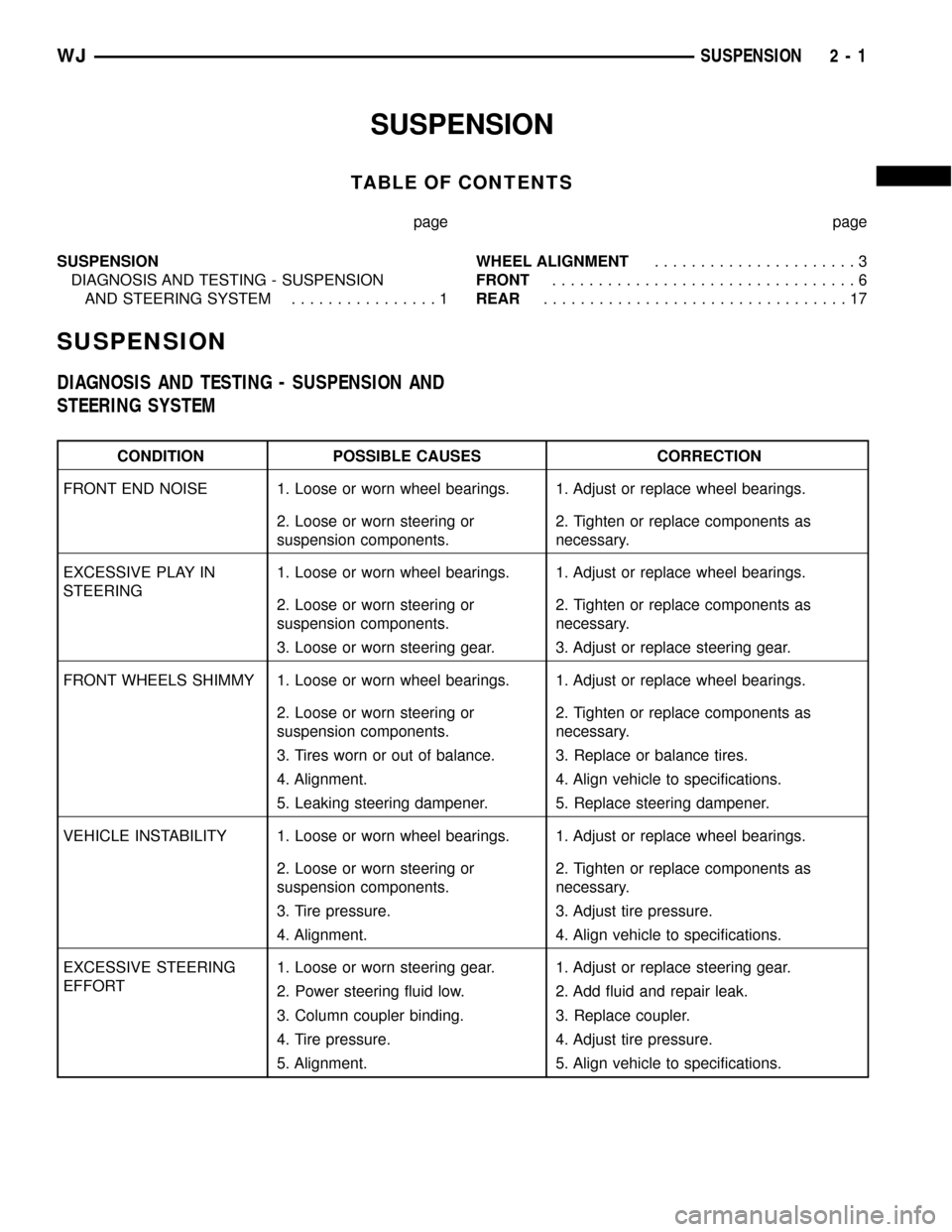
DIAGNOSIS AND TESTING - SUSPENSION
AND STEERING SYSTEM................1WHEEL ALIGNMENT......................3
FRONT.................................6
REAR.................................17
SUSPENSION
DIAGNOSIS AND TESTING - SUSPENSION AND
STEERING SYSTEM
CONDITION POSSIBLE CAUSES CORRECTION
FRONT END NOISE 1. Loose or worn wheel bearings. 1. Adjust or replace wheel bearings.
2. Loose or worn steering or
suspension components.2. Tighten or replace components as
necessary.
EXCESSIVE PLAY IN
STEERING1. Loose or worn wheel bearings. 1. Adjust or replace wheel bearings.
2. Loose or worn steering or
suspension components.2. Tighten or replace components as
necessary.
3. Loose or worn steering gear. 3. Adjust or replace steering gear.
FRONT WHEELS SHIMMY 1. Loose or worn wheel bearings. 1. Adjust or replace wheel bearings.
2. Loose or worn steering or
suspension components.2. Tighten or replace components as
necessary.
3. Tires worn or out of balance. 3. Replace or balance tires.
4. Alignment. 4. Align vehicle to specifications.
5. Leaking steering dampener. 5. Replace steering dampener.
VEHICLE INSTABILITY 1. Loose or worn wheel bearings. 1. Adjust or replace wheel bearings.
2. Loose or worn steering or
suspension components.2. Tighten or replace components as
necessary.
3. Tire pressure. 3. Adjust tire pressure.
4. Alignment. 4. Align vehicle to specifications.
EXCESSIVE STEERING
EFFORT1. Loose or worn steering gear. 1. Adjust or replace steering gear.
2. Power steering fluid low. 2. Add fluid and repair leak.
3. Column coupler binding. 3. Replace coupler.
4. Tire pressure. 4. Adjust tire pressure.
5. Alignment. 5. Align vehicle to specifications.
WJSUSPENSION 2 - 1
Page 23 of 2199

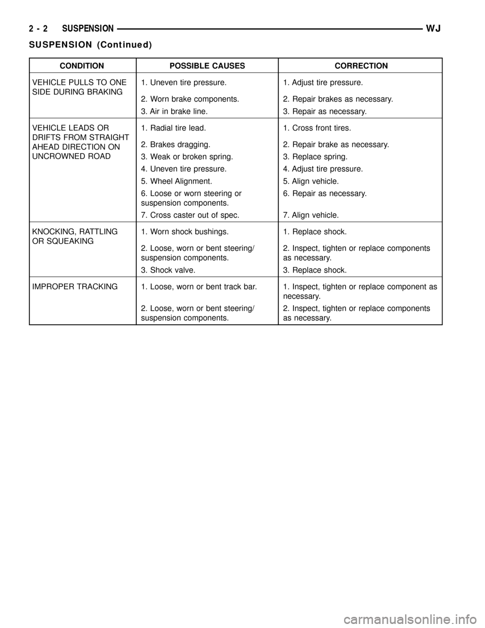
CONDITION POSSIBLE CAUSES CORRECTION
VEHICLE PULLS TO ONE
SIDE DURING BRAKING1. Uneven tire pressure. 1. Adjust tire pressure.
2. Worn brake components. 2. Repair brakes as necessary.
3. Air in brake line. 3. Repair as necessary.
VEHICLE LEADS OR
DRIFTS FROM STRAIGHT
AHEAD DIRECTION ON
UNCROWNED ROAD1. Radial tire lead. 1. Cross front tires.
2. Brakes dragging. 2. Repair brake as necessary.
3. Weak or broken spring. 3. Replace spring.
4. Uneven tire pressure. 4. Adjust tire pressure.
5. Wheel Alignment. 5. Align vehicle.
6. Loose or worn steering or
suspension components.6. Repair as necessary.
7. Cross caster out of spec. 7. Align vehicle.
KNOCKING, RATTLING
OR SQUEAKING1. Worn shock bushings. 1. Replace shock.
2. Loose, worn or bent steering/
suspension components.2. Inspect, tighten or replace components
as necessary.
3. Shock valve. 3. Replace shock.
IMPROPER TRACKING 1. Loose, worn or bent track bar. 1. Inspect, tighten or replace component as
necessary.
2. Loose, worn or bent steering/
suspension components.2. Inspect, tighten or replace components
as necessary.
2 - 2 SUSPENSIONWJ
SUSPENSION (Continued)
Page 24 of 2199

WHEEL ALIGNMENT
TABLE OF CONTENTS
page page
WHEEL ALIGNMENT
DESCRIPTION..........................3
OPERATION............................3
STANDARD PROCEDURE
STANDARD PROCEDURE - CAMBER.......3STANDARD PROCEDURE - CASTER.......4
STANDARD PROCEDURE - TOE POSITION . . 4
SPECIFICATIONS
ALIGNMENT..........................5
WHEEL ALIGNMENT
DESCRIPTION
Wheel alignment involves the correct positioning of
the wheels in relation to the vehicle. The positioning
is accomplished through suspension and steering
linkage adjustments. An alignment is considered
essential for efficient steering, good directional stabil-
ity and to minimize tire wear. The most important
measurements of an alignment are caster, camber
and toe position (Fig. 1).
CAUTION: Never attempt to modify suspension or
steering components by heating or bending.
CAUTION: Components attached with a nut and cot-
ter pin must be torqued to specification. Then if the
slot in the nut does not line up with the cotter pin
hole, tighten nut until it is aligned. Never loosen the
nut to align the cotter pin hole.
NOTE: Periodic lubrication of the front suspension/
steering system components may be required. Rub-
ber bushings must never be lubricated, Refer to
Lubrication And Maintenance for the recommended
maintenance schedule.
OPERATION
²CASTERis the forward or rearward tilt of the
steering knuckle from vertical. Tilting the top of the
knuckle rearward provides positive caster. Tilting the
top of the knuckle forward provides negative caster.
Caster is a directional stability angle. This angle
enables the front wheels to return to a straight
ahead position after turns (Fig. 1).
²CAMBERis the inward or outward tilt of the
wheel relative to the center of the vehicle. Tilting the
top of the wheel inward provides negative camber.
Tilting the top of the wheel outward provides positive
camber. Incorrect camber will cause wear on theinside or outside edge of the tire. The angle is not
adjustable, damaged component(s) must be replaced
to correct the camber angle (Fig. 1).
²WHEEL TOE POSITIONis the difference
between the leading inside edges and trailing inside
edges of the front tires. Incorrect wheel toe position
is the most common cause of unstable steering and
uneven tire wear. The wheel toe position is thefinal
front wheel alignment adjustment (Fig. 1).
²STEERING AXIS INCLINATION ANGLEis
measured in degrees and is the angle that the steer-
ing knuckles are tilted. The inclination angle has a
fixed relationship with the camber angle. It will not
change except when a spindle or ball stud is dam-
aged or bent. The angle is not adjustable, damaged
component(s) must be replaced to correct the steering
axis inclination angle.
²THRUST ANGLEis the angle of the rear axle
relative to the centerline of the vehicle. Incorrect
thrust angle can cause off-center steering and exces-
sive tire wear. This angle is not adjustable, damaged
component(s) must be replaced to correct the thrust
angle (Fig. 1).
STANDARD PROCEDURE
STANDARD PROCEDURE - CAMBER
Before each alignment reading the vehicle should
be jounced (rear first, then front). Grasp each
bumper at the center and jounce the vehicle up and
down three times. Always release the bumper in the
down position.
To obtain an accurate alignment, a 4 wheel align-
ment machine must be used and the equipment cali-
bration verified.
The wheel camber angle is preset. This angle is not
adjustable and cannot be altered.
WJWHEEL ALIGNMENT 2 - 3
Page 25 of 2199

STANDARD PROCEDURE - CASTER
Before each alignment reading the vehicle should
be jounced (rear first, then front). Grasp each
bumper at the center and jounce the vehicle up and
down three times. Always release the bumper in the
down position.
To obtain an accurate alignment, a 4 wheel align-
ment machine must be used and the equipment cali-
bration verified.
The wheel caster angle is preset. This angle is not
adjustable and cannot be altered.
STANDARD PROCEDURE - TOE POSITION
Before each alignment reading the vehicle should
be jounced (rear first, then front). Grasp each
bumper at the center and jounce the vehicle up and
down three times. Always release the bumper in the
down position.To obtain an accurate alignment, a 4 wheel align-
ment machine must be used and the equipment cali-
bration verified.
NOTE: For an accurate wheel toe position adjust-
ment the engine must be engine running.
(1) Apply parking brakes.
(2) Start the engine and turn wheels both ways
before straightening the steering wheel. Center and
secure the steering wheel.
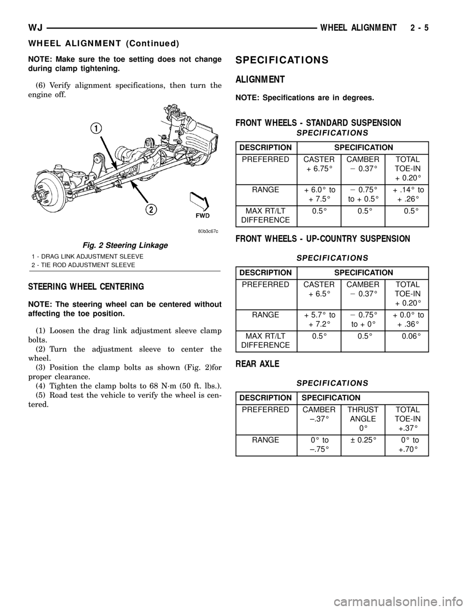
(3) Loosen the tie rod adjustment sleeve clamp
bolts (Fig. 2).
(4) Turn the sleeve to obtain the preferred positive
TOE-IN specification. Position the clamp bolts as
shown (Fig. 2) for proper clearance.
(5) Tighten the clamp bolts to 68 N´m (50 ft. lbs.).
Fig. 1 Wheel Alignment Measurements
1 - WHEEL CENTERLINE
2 - NEGATIVE CAMBER ANGLE
3 - PIVOT CENTERLINE
4 - SCRUB RADIUS
5 - TRUE VERTICAL6 - KING PIN
7 - VERTICAL
8 - POSITIVE CASTER
2 - 4 WHEEL ALIGNMENTWJ
WHEEL ALIGNMENT (Continued)
Page 26 of 2199

NOTE: Make sure the toe setting does not change
during clamp tightening.
(6) Verify alignment specifications, then turn the
engine off.
STEERING WHEEL CENTERING
NOTE: The steering wheel can be centered without
affecting the toe position.
(1) Loosen the drag link adjustment sleeve clamp
bolts.
(2) Turn the adjustment sleeve to center the
wheel.
(3) Position the clamp bolts as shown (Fig. 2)for
proper clearance.
(4) Tighten the clamp bolts to 68 N´m (50 ft. lbs.).
(5) Road test the vehicle to verify the wheel is cen-
tered.
SPECIFICATIONS
ALIGNMENT
NOTE: Specifications are in degrees.
FRONT WHEELS - STANDARD SUSPENSION
SPECIFICATIONS
DESCRIPTION SPECIFICATION
PREFERRED CASTER
+ 6.75ÉCAMBER
20.37ÉTOTAL
TOE-IN
+ 0.20É
RANGE + 6.0É to
+ 7.5É20.75É
to + 0.5É+ .14É to
+ .26É
MAX RT/LT
DIFFERENCE0.5É 0.5É 0.5É
FRONT WHEELS - UP-COUNTRY SUSPENSION
SPECIFICATIONS
DESCRIPTION SPECIFICATION
PREFERRED CASTER
+ 6.5ÉCAMBER
20.37ÉTOTAL
TOE-IN
+ 0.20É
RANGE + 5.7É to
+ 7.2É20.75É
to+0É+ 0.0É to
+ .36É
MAX RT/LT
DIFFERENCE0.5É 0.5É 0.06É
REAR AXLE
SPECIFICATIONS
DESCRIPTION SPECIFICATION
PREFERRED CAMBER
±.37ÉTHRUST
ANGLE
0ÉTOTAL
TOE-IN
+.37É
RANGE 0É to
±.75É 0.25É 0É to
+.70É
Fig. 2 Steering Linkage
1 - DRAG LINK ADJUSTMENT SLEEVE
2 - TIE ROD ADJUSTMENT SLEEVE
WJWHEEL ALIGNMENT 2 - 5
WHEEL ALIGNMENT (Continued)
Page 65 of 2199

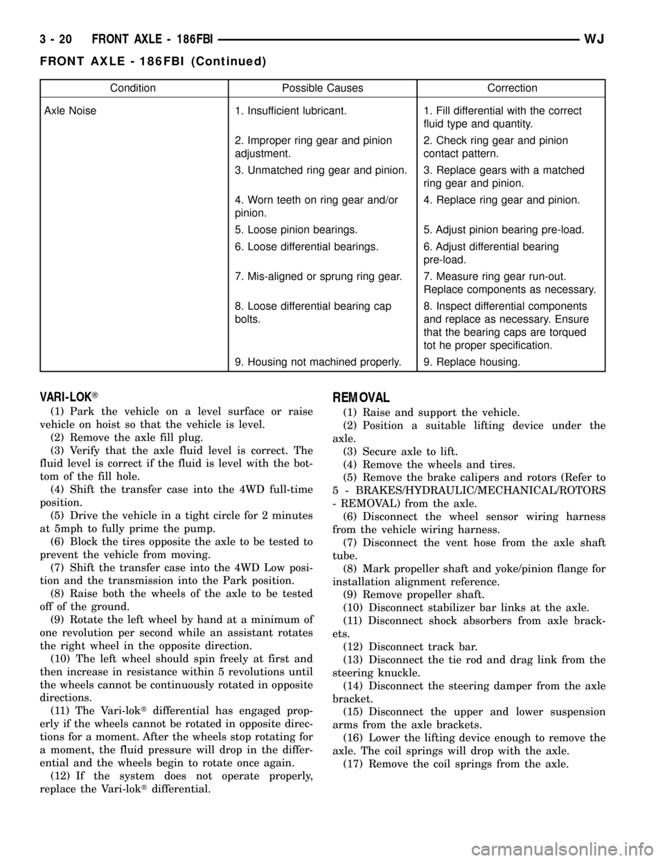
Condition Possible Causes Correction
Axle Noise 1. Insufficient lubricant. 1. Fill differential with the correct
fluid type and quantity.
2. Improper ring gear and pinion
adjustment.2. Check ring gear and pinion
contact pattern.
3. Unmatched ring gear and pinion. 3. Replace gears with a matched
ring gear and pinion.
4. Worn teeth on ring gear and/or
pinion.4. Replace ring gear and pinion.
5. Loose pinion bearings. 5. Adjust pinion bearing pre-load.
6. Loose differential bearings. 6. Adjust differential bearing
pre-load.
7. Mis-aligned or sprung ring gear. 7. Measure ring gear run-out.
Replace components as necessary.
8. Loose differential bearing cap
bolts.8. Inspect differential components
and replace as necessary. Ensure
that the bearing caps are torqued
tot he proper specification.
9. Housing not machined properly. 9. Replace housing.
VARI-LOKT
(1) Park the vehicle on a level surface or raise
vehicle on hoist so that the vehicle is level.
(2) Remove the axle fill plug.
(3) Verify that the axle fluid level is correct. The
fluid level is correct if the fluid is level with the bot-
tom of the fill hole.
(4) Shift the transfer case into the 4WD full-time
position.
(5) Drive the vehicle in a tight circle for 2 minutes
at 5mph to fully prime the pump.
(6) Block the tires opposite the axle to be tested to
prevent the vehicle from moving.
(7) Shift the transfer case into the 4WD Low posi-
tion and the transmission into the Park position.
(8) Raise both the wheels of the axle to be tested
off of the ground.
(9) Rotate the left wheel by hand at a minimum of
one revolution per second while an assistant rotates
the right wheel in the opposite direction.
(10) The left wheel should spin freely at first and
then increase in resistance within 5 revolutions until
the wheels cannot be continuously rotated in opposite
directions.
(11) The Vari-loktdifferential has engaged prop-
erly if the wheels cannot be rotated in opposite direc-
tions for a moment. After the wheels stop rotating for
a moment, the fluid pressure will drop in the differ-
ential and the wheels begin to rotate once again.
(12) If the system does not operate properly,
replace the Vari-loktdifferential.
REMOVAL
(1) Raise and support the vehicle.
(2) Position a suitable lifting device under the
axle.
(3) Secure axle to lift.
(4) Remove the wheels and tires.
(5) Remove the brake calipers and rotors (Refer to
5 - BRAKES/HYDRAULIC/MECHANICAL/ROTORS
- REMOVAL) from the axle.
(6) Disconnect the wheel sensor wiring harness
from the vehicle wiring harness.
(7) Disconnect the vent hose from the axle shaft
tube.
(8) Mark propeller shaft and yoke/pinion flange for
installation alignment reference.
(9) Remove propeller shaft.
(10) Disconnect stabilizer bar links at the axle.
(11) Disconnect shock absorbers from axle brack-
ets.
(12) Disconnect track bar.
(13) Disconnect the tie rod and drag link from the
steering knuckle.
(14) Disconnect the steering damper from the axle
bracket.
(15) Disconnect the upper and lower suspension
arms from the axle brackets.
(16) Lower the lifting device enough to remove the
axle. The coil springs will drop with the axle.
(17) Remove the coil springs from the axle.
3 - 20 FRONT AXLE - 186FBIWJ
FRONT AXLE - 186FBI (Continued)
Page 66 of 2199

INSTALLATION
CAUTION: The weight of the vehicle must be sup-
ported by the springs before suspension arms and
track bar fasteners can be tightened. If springs are
not at their normal ride position, ride height and
handling could be affected.
(1) Install the springs and retainer clips. Tighten
the retainer bolts to 21 N´m (16 ft. lbs.).
(2) Support the axle on a lifting device and posi-
tion axle under the vehicle.
(3) Raise the axle and align it with the spring
pads.
(4) Position the upper and lower suspension arms
in the axle brackets. Loosely install bolts and nuts to
hold suspension arms to the axle brackets.
(5) Install vent hose to the axle shaft tube.
(6) Install track bar in the axle bracket and install
the bolt loosely.
(7) Install shock absorbers and tighten the bolts to
23 N´m (17 ft. lbs.).
(8) Install stabilizer bar links to the axle brackets
and tighten the nuts to 95 N´m (70 ft. lbs.).
(9) Install drag link and tie rod to the steering
knuckles.
(10) Install steering damper to the axle bracket
and tighten the nut to 75 N´m (55 ft. lbs.).
(11) Install the brake rotors (Refer to 5 - BRAKES/
HYDRAULIC/MECHANICAL/ROTORS - INSTALLA-
TION) and calipers.
(12) Connect the wheel speed sensor wiring har-
ness to the vehicle wiring harness.
(13) Align the previously made marks on the pro-
peller shaft and the yoke/pinion flange.
(14) Install propeller shaft to pinion flange bolts ,
if equipped.
(15) Install propeller shaft to yoke straps and
bolts, if equipped.
(16) Check and fill axle lubricant.
(17) Install the wheel and tire assemblies.
(18) Remove the lifting device from the axle and
lower the vehicle.
(19) Tighten the upper suspension arm nuts to 75
N´m (55 ft. lbs.). Tighten the lower suspension arm
nuts to 115 N´m (85 ft. lbs.).
(20) Tighten the track bar bolt at the axle bracket
to 100 N´m (74 ft. lbs.).
(21) Check the front wheel alignment.
ADJUSTMENTS
Ring and pinion gears are supplied as matched
sets only. The identifying numbers for the ring and
pinion gear are etched onto each gear (Fig. 3). A plus
(+) number, minus (±) number or zero (0) is etched
into the face of the pinion gear. This number is theamount (in thousandths of an inch) the depth varies
from the standard depth setting of a pinion etched
with a (0). The standard setting from the center line
of the ring gear to the back face of the pinion is 92.1
mm (3.625 in.). The standard depth provides the best
gear tooth contact pattern. Refer to Backlash and
Contact Pattern Analysis paragraph in this section
for additional information.
Compensation for pinion depth variance is
achieved with a select shim/oil slinger. The shims are
placed between the rear pinion bearing and the pin-
ion gear head (Fig. 4).
Fig. 3 PINION GEAR ID NUMBERS
1 - PRODUCTION NUMBERS
2 - DRIVE PINION GEAR DEPTH VARIANCE
3 - GEAR MATCHING NUMBER
Fig. 4 ADJUSTMENT SHIM LOCATIONS
1 - PINION DEPTH SHIM/OIL SLINGER
2 - DIFFERENTIAL BEARING SHIM
3 - RING GEAR
4 - DIFFERENTIAL BEARING SHIM
5 - COLLAPSIBLE SPACER
WJFRONT AXLE - 186FBI 3 - 21
FRONT AXLE - 186FBI (Continued)
Page 183 of 2199

ADJUSTABLE PEDAL SWITCH
REMOVAL
(1) Remove the steering column opening cover
(Fig. 2)(Refer to 23 - BODY/INSTRUMENT PANEL/
STEERING COLUMN OPENING COVER - REMOV-
AL).
(2) Disconnect the electrical connector from the
adjustable pedal switch.
(3) Remove the switch from the steering column
opening cover by squeezing the retaining clips
together and pushing the switch outwards (Fig. 3).
INSTALLATION
(1) Install the switch to the steering column open-
ing cover by pushing the switch inwards seating the
retaining clips to the steering column opening cover
(Fig. 3).
(2) Reconnect the electrical connector to the
adjustable pedal switch.
(3) Install the steering column opening cover (Fig.
2)(Refer to 23 - BODY/INSTRUMENT PANEL/
STEERING COLUMN OPENING COVER - INSTAL-
LATION).
BRAKE LINES
DESCRIPTION
Flexible rubber hose is used at both front brakes,
rear brakes and at the rear axle junction block. Dou-
ble walled steel tubing is used. Double inverted style
and ISO style flares are used on the brake lines.
DIAGNOSIS AND TESTING - BRAKE HOSES
AND LINES
Flexible rubber hose is used at both front and rear
brakes and at the rear axle junction block. Inspect
the hoses whenever the brake system is serviced, at
every engine oil change, or whenever the vehicle is in
for service.
Inspect the hoses for surface cracking, scuffing, or
worn spots. Replace any brake hose immediately if
the fabric casing of the hose is exposed due to cracks
or abrasions.
Also check brake hose installation. Faulty installa-
tion can result in kinked, twisted hoses, or contact
with the wheels and tires or other chassis compo-
nents. All of these conditions can lead to scuffing,
cracking and eventual failure.
The steel brake lines should be inspected periodi-
cally for evidence of corrosion, twists, kinks, leaks, or
other damage. Heavily corroded lines will eventually
rust through causing leaks. In any case, corroded or
damaged brake lines should be replaced.
Factory replacement brake lines and hoses are rec-
ommended to ensure quality, correct length and supe-
rior fatigue life. Care should be taken to make sure
that brake line and hose mating surfaces are clean
and free from nicks and burrs. Also remember that
right and left brake hoses are not interchangeable.
Use new copper gaskets at all caliper connections.
Be sure brake line connections are properly made
(not cross threaded) and tightened to recommended
torque.
Fig. 2 STEERING COLUMN OPENING COVER
REMOVAL/INSTALL
1 - INSTRUMENT PANEL TOP PAD
2 - STEERING COLUMN OPENING COVER
3 - SCREW (3)
Fig. 3 ADJUSTABLE PEDAL SWITCH
1 - RETAINING CLIPS
2 - ELECTRICAL CONNECTION
5 - 8 BRAKES - BASEWJ
Page 200 of 2199

STANDARD PROCEDURE - MASTER CYLINDER
BLEEDING PROCEDURE
A new master cylinder should be bled before instal-
lation on the vehicle. Required bleeding tools include
bleed tubes and a wood dowel to stroke the pistons.
Bleed tubes can be fabricated from brake line.
(1) Mount master cylinder in vise with brass jaws.
(2) Attach bleed tubes to cylinder outlet ports.
Then position each tube end into the bottom of the
reservoir (Fig. 50).
(3) Fill reservoir with fresh brake fluid.
(4) Press cylinder pistons inward with wood dowel.
Then release pistons and allow them to return under
spring pressure. Continue bleeding operations until
air bubbles are no longer visible in fluid.
REMOVAL
(1) Remove the wire connector from the brake fluid
level sensor.
(2) Remove brake lines from master cylinder.
(3) Remove nuts that attach master cylinder to
booster studs (Fig. 51).
(4) Remove master cylinder from booster.
INSTALLATION
NOTE: Bleed new master cylinder on bench before
installation, refer to Service Procedures.
(1) Have an assistant depress the brake pedal
while guiding the master cylinder on the booster rod
and mounting studs.
CAUTION: Do not depress brake pedal too hard and
ensure the booster rod is in the master cylinder pis-
ton or booster/master cylinder damage will occur.(2) Install master cylinder mounting nuts and
tighten nuts to 25 N´m (18 lb. lbs.).
NOTE: Use original or factory replacement nuts only.
(3) Install brake lines and tighten to 16 N´m (144
in. lbs.).
(4) Install fluid level sensor connector.
(5) Fill and bleed brake system.
PEDAL
DESCRIPTION
DESCRIPTION - STANDARD PEDAL
A suspended-type brake pedal is used, the pedal
pivots on a shaft mounted in the pedal support
bracket. The bracket is attached to the dash panel.
The brake pedal assembly and pedal pad are the
only serviceable component.
DESCRIPTION - ADJUSTABLE PEDALS
The Adjustable Pedals System (APS) is designed to
enable the fore and aft repositioning of the brake and
accelerator pedals. This results in improved ergonom-
ics in relation to the steering wheel for taller and
shorter drivers. Being able to adjust the pedal posi-
Fig. 50 Master Cylinder Bleeding
1 - BLEEDING TUBES
2 - RESERVOIR
Fig. 51 Master Cylinder Mounting
1 - MOUNTING NUT
2 - SENSOR CONNECTOR
3 - MOUNTING NUT
4 - BRAKE LINES
WJBRAKES - BASE 5 - 25
MASTER CYLINDER (Continued)
Page 201 of 2199

tions also allows the driver to set steering wheel tilt
and seat position to the most comfortable position.
The position of the brake and accelerator pedals can
be adjusted without compromising safety or comfort
in actuating the pedals. Repositioning the pedals
does not change the effort required for actuation.
Change of pedal position is accomplished by means
of a motor driven screw. Operating the adjustable
pedal switch activates the pedal drive motor. The
pedal drive motor turns a screw that changes the
position of the brake and accelerator pedals. The
pedal can be moved rearward (closer to the driver) or
forward (away from driver). The brake pedal is
moved on its drive screw to a position where the
driver feels most comfortable (Fig. 52).
The accelerator pedal is moved at the same time
and the same distance as the brake pedal. The accel-
erator pedal adjustment screw is turned by a flexible
shaft slaved off the brake adjustment screw.
Neither the pedal drive motor nor drive mecha-
nism are subject to the mechanical stress of brake or
accelerator application.
²SYSTEM FEATURES:
²Range of Adjustment: The pedals may be
adjusted up to 3 in. (75 mm)
²Pedal Adjustment Speed: 0.5 in./sec (12.5
mm/sec)
²Pedal Adjustment Inhibitors: Pedal adjust-
ment is inhibited when the vehicle is in reverse or
when cruise control is activated.
²Memory: An optional memory feature is avail-
able. This allows storing of one or two preferred
pedal positions in the Adjustable Pedal Module
(APM). A preferred position can be stored and
recalled using the door-mounted switches. A stored
pedal position can be recalled (but not stored)
using the Remote Keyless Entry (RKE).
²
Adjustable Pedal Feedback Message: The Elec-
tronic Vehicle Information Center (EVIC) will display
a message when the APS is disabled. ie:9Adjustable
Pedal Disabled - Cruise Control Engaged9or9Adjust-
able Pedal Disabled - Vehicle in Reverse9.
²Damage Prevention: Foot pressure or debris
can stall pedal adjustment. In order to avoid dam-
age to system components during pedal adjust-
ment, the APM will monitor pedal position sensor
voltage. If the APM does not detect expected volt-
age change within 1.5 seconds, it will cut power to
the adjustable pedal motor.
OPERATION
The brake pedal is attached to the booster push
rod. When the pedal is depressed, the primary
booster push rod is depressed which moves the
booster secondary rod. The booster secondary rod
depresses the master cylinder piston.
REMOVAL
REMOVAL - NON-ADJUSTABLE PEDAL
(1) Remove retainer clip that holds booster to
pedal pin (Fig. 53).
Fig. 52 ADJUSTABLE PEDALS ASSEMBLY
1 - HARNESS
2 - ADJUSTABLE PEDAL BRACKET
3 - CABLE
4 - ACCELERATOR PEDAL
5 - BRAKE PEDAL
6 - ADJUSTABLE PEDAL MOTOR
7 - BRAKE LIGHT SWITCH
8 - ADJUSTABLE PEDALS MODULE
Fig. 53 Push Rod Retainer Clip
1 - RETAINER CLIP
2 - PUSH ROD
3 - PEDAL PIN
5 - 26 BRAKES - BASEWJ
PEDAL (Continued)