cylinder head JEEP GRAND CHEROKEE 2002 WJ / 2.G Workshop Manual
[x] Cancel search | Manufacturer: JEEP, Model Year: 2002, Model line: GRAND CHEROKEE, Model: JEEP GRAND CHEROKEE 2002 WJ / 2.GPages: 2199, PDF Size: 76.01 MB
Page 13 of 2199
INTERNATIONAL SYMBOLS
DESCRIPTION
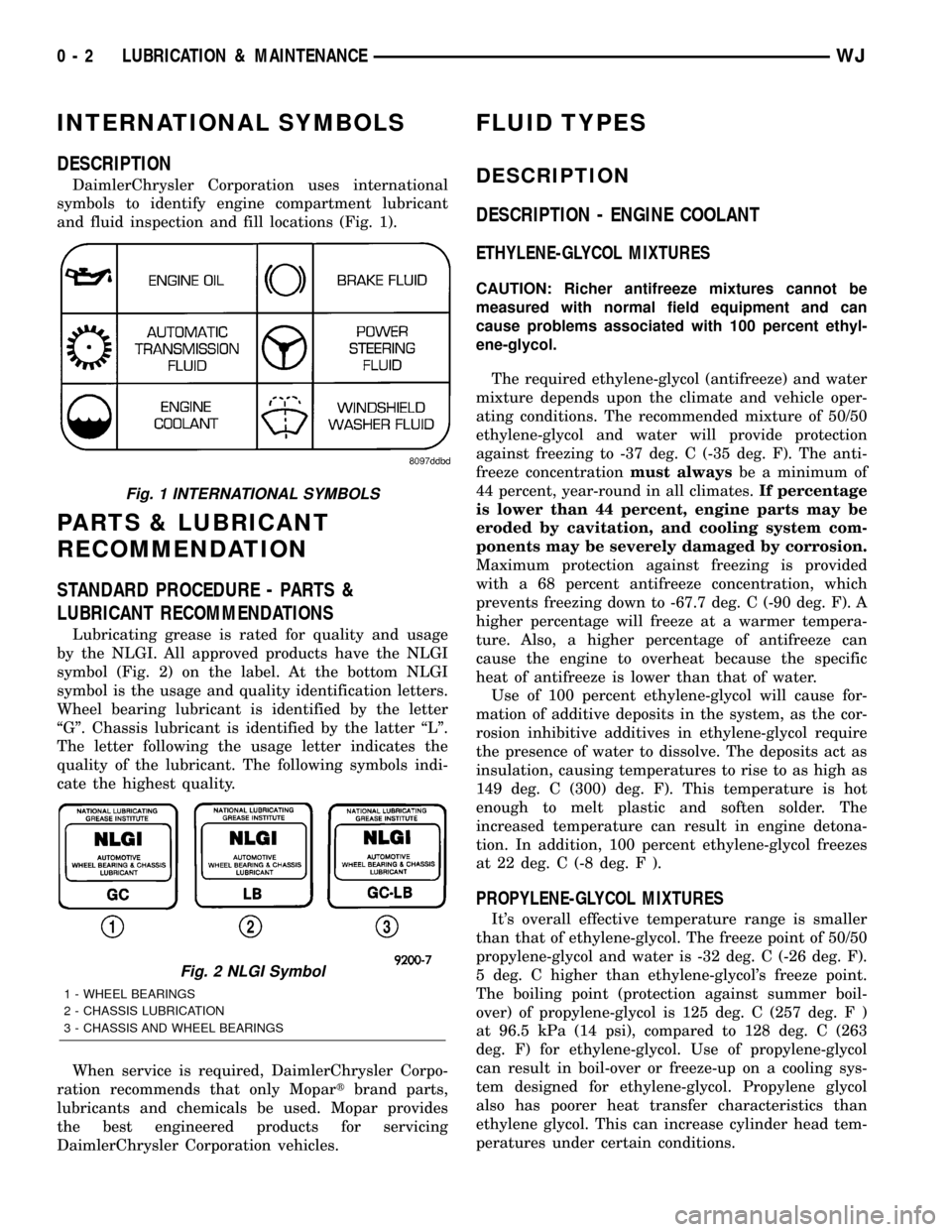
DaimlerChrysler Corporation uses international
symbols to identify engine compartment lubricant
and fluid inspection and fill locations (Fig. 1).
PARTS & LUBRICANT
RECOMMENDATION
STANDARD PROCEDURE - PARTS &
LUBRICANT RECOMMENDATIONS
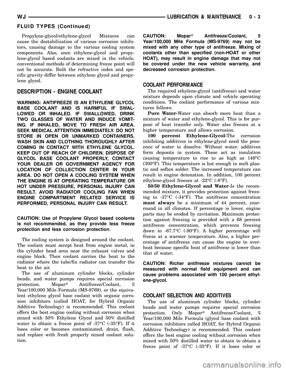
Lubricating grease is rated for quality and usage
by the NLGI. All approved products have the NLGI
symbol (Fig. 2) on the label. At the bottom NLGI
symbol is the usage and quality identification letters.
Wheel bearing lubricant is identified by the letter
ªGº. Chassis lubricant is identified by the latter ªLº.
The letter following the usage letter indicates the
quality of the lubricant. The following symbols indi-
cate the highest quality.
When service is required, DaimlerChrysler Corpo-
ration recommends that only Mopartbrand parts,
lubricants and chemicals be used. Mopar provides
the best engineered products for servicing
DaimlerChrysler Corporation vehicles.
FLUID TYPES
DESCRIPTION
DESCRIPTION - ENGINE COOLANT
ETHYLENE-GLYCOL MIXTURES
CAUTION: Richer antifreeze mixtures cannot be
measured with normal field equipment and can
cause problems associated with 100 percent ethyl-
ene-glycol.
The required ethylene-glycol (antifreeze) and water
mixture depends upon the climate and vehicle oper-
ating conditions. The recommended mixture of 50/50
ethylene-glycol and water will provide protection
against freezing to -37 deg. C (-35 deg. F). The anti-
freeze concentrationmust alwaysbe a minimum of
44 percent, year-round in all climates.If percentage
is lower than 44 percent, engine parts may be
eroded by cavitation, and cooling system com-
ponents may be severely damaged by corrosion.
Maximum protection against freezing is provided
with a 68 percent antifreeze concentration, which
prevents freezing down to -67.7 deg. C (-90 deg. F). A
higher percentage will freeze at a warmer tempera-
ture. Also, a higher percentage of antifreeze can
cause the engine to overheat because the specific
heat of antifreeze is lower than that of water.
Use of 100 percent ethylene-glycol will cause for-
mation of additive deposits in the system, as the cor-
rosion inhibitive additives in ethylene-glycol require
the presence of water to dissolve. The deposits act as
insulation, causing temperatures to rise to as high as
149 deg. C (300) deg. F). This temperature is hot
enough to melt plastic and soften solder. The
increased temperature can result in engine detona-
tion. In addition, 100 percent ethylene-glycol freezes
at 22 deg. C (-8 deg. F ).
PROPYLENE-GLYCOL MIXTURES
It's overall effective temperature range is smaller
than that of ethylene-glycol. The freeze point of 50/50
propylene-glycol and water is -32 deg. C (-26 deg. F).
5 deg. C higher than ethylene-glycol's freeze point.
The boiling point (protection against summer boil-
over) of propylene-glycol is 125 deg. C (257 deg. F )
at 96.5 kPa (14 psi), compared to 128 deg. C (263
deg. F) for ethylene-glycol. Use of propylene-glycol
can result in boil-over or freeze-up on a cooling sys-
tem designed for ethylene-glycol. Propylene glycol
also has poorer heat transfer characteristics than
ethylene glycol. This can increase cylinder head tem-
peratures under certain conditions.
Fig. 1 INTERNATIONAL SYMBOLS
Fig. 2 NLGI Symbol
1 - WHEEL BEARINGS
2 - CHASSIS LUBRICATION
3 - CHASSIS AND WHEEL BEARINGS
0 - 2 LUBRICATION & MAINTENANCEWJ
Page 14 of 2199
Propylene-glycol/ethylene-glycol Mixtures can
cause the destabilization of various corrosion inhibi-
tors, causing damage to the various cooling system
components. Also, once ethylene-glycol and propy-
lene-glycol based coolants are mixed in the vehicle,
conventional methods of determining freeze point will
not be accurate. Both the refractive index and spe-
cific gravity differ between ethylene glycol and propy-
lene glycol.
DESCRIPTION - ENGINE COOLANT
WARNING: ANTIFREEZE IS AN ETHYLENE GLYCOL
BASE COOLANT AND IS HARMFUL IF SWAL-
LOWED OR INHALED. IF SWALLOWED, DRINK
TWO GLASSES OF WATER AND INDUCE VOMIT-
ING. IF INHALED, MOVE TO FRESH AIR AREA.
SEEK MEDICAL ATTENTION IMMEDIATELY. DO NOT
STORE IN OPEN OR UNMARKED CONTAINERS.
WASH SKIN AND CLOTHING THOROUGHLY AFTER
COMING IN CONTACT WITH ETHYLENE GLYCOL.
KEEP OUT OF REACH OF CHILDREN. DISPOSE OF
GLYCOL BASE COOLANT PROPERLY, CONTACT
YOUR DEALER OR GOVERNMENT AGENCY FOR
LOCATION OF COLLECTION CENTER IN YOUR
AREA. DO NOT OPEN A COOLING SYSTEM WHEN
THE ENGINE IS AT OPERATING TEMPERATURE OR
HOT UNDER PRESSURE, PERSONAL INJURY CAN
RESULT. AVOID RADIATOR COOLING FAN WHEN
ENGINE COMPARTMENT RELATED SERVICE IS
PERFORMED, PERSONAL INJURY CAN RESULT.
CAUTION: Use of Propylene Glycol based coolants
is not recommended, as they provide less freeze
protection and less corrosion protection.
The cooling system is designed around the coolant.
The coolant must accept heat from engine metal, in
the cylinder head area near the exhaust valves and
engine block. Then coolant carries the heat to the
radiator where the tube/fin radiator can transfer the
heat to the air.
The use of aluminum cylinder blocks, cylinder
heads, and water pumps requires special corrosion
protection. MopartAntifreeze/Coolant, 5
Year/100,000 Mile Formula (MS-9769), or the equiva-
lent ethylene glycol base coolant with organic corro-
sion inhibitors (called HOAT, for Hybrid Organic
Additive Technology) is recommended. This coolant
offers the best engine cooling without corrosion when
mixed with 50% Ethylene Glycol and 50% distilled
water to obtain a freeze point of -37ÉC (-35ÉF). If it
loses color or becomes contaminated, drain, flush,
and replace with fresh properly mixed coolant solu-
tion.CAUTION: MoparTAntifreeze/Coolant, 5
Year/100,000 Mile Formula (MS-9769) may not be
mixed with any other type of antifreeze. Mixing of
coolants other than specified (non-HOAT or other
HOAT), may result in engine damage that may not
be covered under the new vehicle warranty, and
decreased corrosion protection.
COOLANT PERFORMANCE
The required ethylene-glycol (antifreeze) and water
mixture depends upon climate and vehicle operating
conditions. The coolant performance of various mix-
tures follows:
Pure Water-Water can absorb more heat than a
mixture of water and ethylene-glycol. This is for pur-
pose of heat transfer only. Water also freezes at a
higher temperature and allows corrosion.
100 percent Ethylene-Glycol-The corrosion
inhibiting additives in ethylene-glycol need the pres-
ence of water to dissolve. Without water, additives
form deposits in system. These act as insulation
causing temperature to rise to as high as 149ÉC
(300ÉF). This temperature is hot enough to melt plas-
tic and soften solder. The increased temperature can
result in engine detonation. In addition, 100 percent
ethylene-glycol freezes at -22ÉC (-8ÉF).
50/50 Ethylene-Glycol and Water-Is the recom-
mended mixture, it provides protection against freez-
ing to -37ÉC (-34ÉF). The antifreeze concentration
must alwaysbe a minimum of 44 percent, year-
round in all climates. If percentage is lower, engine
parts may be eroded by cavitation. Maximum protec-
tion against freezing is provided with a 68 percent
antifreeze concentration, which prevents freezing
down to -67.7ÉC (-90ÉF). A higher percentage will
freeze at a warmer temperature. Also, a higher per-
centage of antifreeze can cause the engine to over-
heat because specific heat of antifreeze is lower than
that of water.
CAUTION: Richer antifreeze mixtures cannot be
measured with normal field equipment and can
cause problems associated with 100 percent ethyl-
ene-glycol.
COOLANT SELECTION AND ADDITIVES
The use of aluminum cylinder blocks, cylinder
heads and water pumps requires special corrosion
protection. Only MopartAntifreeze/Coolant, 5
Year/100,000 Mile Formula (glycol base coolant with
corrosion inhibitors called HOAT, for Hybrid Organic
Additive Technology) is recommended. This coolant
offers the best engine cooling without corrosion when
mixed with 50% distilled water to obtain to obtain a
freeze point of -37ÉC (-35ÉF). If it loses color or
WJLUBRICATION & MAINTENANCE 0 - 3
FLUID TYPES (Continued)
Page 230 of 2199
CONDITION POSSIBLE CAUSES CORRECTION
17. Viscous fan drive not operating
properly.17. Check fan drive operation and replace as
necessary. (Refer to 7 - COOLING/ENGINE/
FAN DRIVE VISCOUS CLUTCH -
DIAGNOSIS AND TESTING).
18. Cylinder head gasket leaking. 18. Check for cylinder head gasket leaks.
(Refer to 7 - COOLING - DIAGNOSIS AND
TESTING). For repair, (Refer to 9 -
ENGINE/CYLINDER HEAD - REMOVAL).
19. Heater core leaking. 19. Check heater core for leaks. (Refer to 24
- HEATING & AIR CONDITIONING/
PLUMBING/HEATER CORE - REMOVAL).
Repair as necessary.
20. Hydraulic fan speed too low or
inopertive.20. Check for
DTC code.
Check fan operation speeds.
Refer to fan speed operation table.
Low power steering pump output. Refer to
power steering pump diagnosis - 4.7L engine.
TEMPERATURE GAUGE
READING IS
INCONSISTENT
(FLUCTUATES, CYCLES
OR IS ERRATIC)1. During cold weather operation,
with the heater blower in the high
position, the gauge reading may
drop slightly.1. A normal condition. No correction is
necessary.
2. Temperature gauge or engine
mounted gauge sensor defective or
shorted. Also, corroded or loose
wiring in this circuit.2. Check operation of gauge and repair if
necessary. Refer to Group 8J, Instrument
cluster.
3. Gauge reading rises when vehicle
is brought to a stop after heavy use
(engine still running)3. A normal condition. No correction is
necessary. Gauge should return to normal
range after vehicle is driven.
4. Gauge reading high after
re-starting a warmed up (hot)
engine.4. A normal condition. No correction is
necessary. The gauge should return to
normal range after a few minutes of engine
operation.
5. Coolant level low in radiator (air
will build up in the cooling system
causing the thermostat to open late).5. Check and correct coolant leaks. (Refer to
7 - COOLING - DIAGNOSIS AND TESTING).
6. Cylinder head gasket leaking
allowing exhaust gas to enter
cooling system causing a thermostat
to open late.6. (a) Check for cylinder head gasket leaks.
(Refer to 7 - COOLING - DIAGNOSIS AND
TESTING).
(b) Check for coolant in the engine oil.
Inspect for white steam emitting from the
exhaust system. Repair as necessary.
WJCOOLING 7 - 7
COOLING (Continued)
Page 234 of 2199
Carefully remove radiator pressure cap from filler
neck and check coolant level. Push down on cap to
disengage it from stop tabs. Wipe inside of filler neck
and examine lower inside sealing seat for nicks,
cracks, paint, dirt and solder residue. Inspect radia-
tor-to- reserve/overflow tank hose for internal
obstructions. Insert a wire through the hose to be
sure it is not obstructed.
Inspect cams on outside of filler neck. If cams are
damaged, seating of pressure cap valve and tester
seal will be affected.
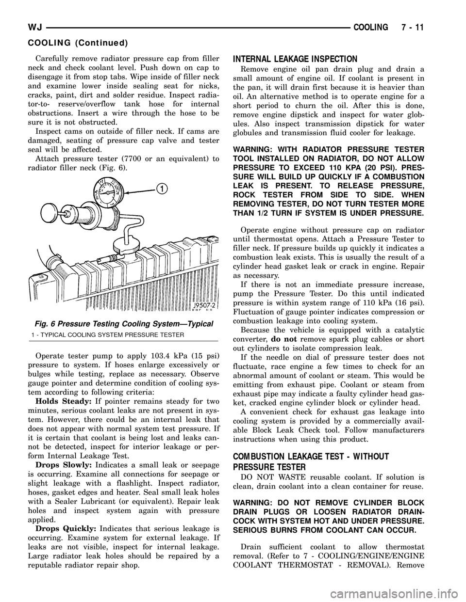
Attach pressure tester (7700 or an equivalent) to
radiator filler neck (Fig. 6).
Operate tester pump to apply 103.4 kPa (15 psi)
pressure to system. If hoses enlarge excessively or
bulges while testing, replace as necessary. Observe
gauge pointer and determine condition of cooling sys-
tem according to following criteria:
Holds Steady:If pointer remains steady for two
minutes, serious coolant leaks are not present in sys-
tem. However, there could be an internal leak that
does not appear with normal system test pressure. If
it is certain that coolant is being lost and leaks can-
not be detected, inspect for interior leakage or per-
form Internal Leakage Test.
Drops Slowly:Indicates a small leak or seepage
is occurring. Examine all connections for seepage or
slight leakage with a flashlight. Inspect radiator,
hoses, gasket edges and heater. Seal small leak holes
with a Sealer Lubricant (or equivalent). Repair leak
holes and inspect system again with pressure
applied.
Drops Quickly:Indicates that serious leakage is
occurring. Examine system for external leakage. If
leaks are not visible, inspect for internal leakage.
Large radiator leak holes should be repaired by a
reputable radiator repair shop.INTERNAL LEAKAGE INSPECTION
Remove engine oil pan drain plug and drain a
small amount of engine oil. If coolant is present in
the pan, it will drain first because it is heavier than
oil. An alternative method is to operate engine for a
short period to churn the oil. After this is done,
remove engine dipstick and inspect for water glob-
ules. Also inspect transmission dipstick for water
globules and transmission fluid cooler for leakage.
WARNING: WITH RADIATOR PRESSURE TESTER
TOOL INSTALLED ON RADIATOR, DO NOT ALLOW
PRESSURE TO EXCEED 110 KPA (20 PSI). PRES-
SURE WILL BUILD UP QUICKLY IF A COMBUSTION
LEAK IS PRESENT. TO RELEASE PRESSURE,
ROCK TESTER FROM SIDE TO SIDE. WHEN
REMOVING TESTER, DO NOT TURN TESTER MORE
THAN 1/2 TURN IF SYSTEM IS UNDER PRESSURE.
Operate engine without pressure cap on radiator
until thermostat opens. Attach a Pressure Tester to
filler neck. If pressure builds up quickly it indicates a
combustion leak exists. This is usually the result of a
cylinder head gasket leak or crack in engine. Repair
as necessary.
If there is not an immediate pressure increase,
pump the Pressure Tester. Do this until indicated
pressure is within system range of 110 kPa (16 psi).
Fluctuation of gauge pointer indicates compression or
combustion leakage into cooling system.
Because the vehicle is equipped with a catalytic
converter,do notremove spark plug cables or short
out cylinders to isolate compression leak.
If the needle on dial of pressure tester does not
fluctuate, race engine a few times to check for an
abnormal amount of coolant or steam. This would be
emitting from exhaust pipe. Coolant or steam from
exhaust pipe may indicate a faulty cylinder head gas-
ket, cracked engine cylinder block or cylinder head.
A convenient check for exhaust gas leakage into
cooling system is provided by a commercially avail-
able Block Leak Check tool. Follow manufacturers
instructions when using this product.
COMBUSTION LEAKAGE TEST - WITHOUT
PRESSURE TESTER
DO NOT WASTE reusable coolant. If solution is
clean, drain coolant into a clean container for reuse.
WARNING: DO NOT REMOVE CYLINDER BLOCK
DRAIN PLUGS OR LOOSEN RADIATOR DRAIN-
COCK WITH SYSTEM HOT AND UNDER PRESSURE.
SERIOUS BURNS FROM COOLANT CAN OCCUR.
Drain sufficient coolant to allow thermostat
removal. (Refer to 7 - COOLING/ENGINE/ENGINE
COOLANT THERMOSTAT - REMOVAL). Remove
Fig. 6 Pressure Testing Cooling SystemÐTypical
1 - TYPICAL COOLING SYSTEM PRESSURE TESTER
WJCOOLING 7 - 11
COOLING (Continued)
Page 236 of 2199
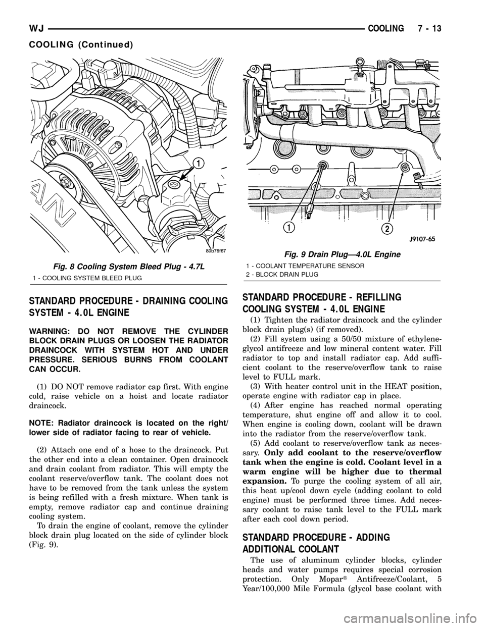
STANDARD PROCEDURE - DRAINING COOLING
SYSTEM - 4.0L ENGINE
WARNING: DO NOT REMOVE THE CYLINDER
BLOCK DRAIN PLUGS OR LOOSEN THE RADIATOR
DRAINCOCK WITH SYSTEM HOT AND UNDER
PRESSURE. SERIOUS BURNS FROM COOLANT
CAN OCCUR.
(1) DO NOT remove radiator cap first. With engine
cold, raise vehicle on a hoist and locate radiator
draincock.
NOTE: Radiator draincock is located on the right/
lower side of radiator facing to rear of vehicle.
(2) Attach one end of a hose to the draincock. Put
the other end into a clean container. Open draincock
and drain coolant from radiator. This will empty the
coolant reserve/overflow tank. The coolant does not
have to be removed from the tank unless the system
is being refilled with a fresh mixture. When tank is
empty, remove radiator cap and continue draining
cooling system.
To drain the engine of coolant, remove the cylinder
block drain plug located on the side of cylinder block
(Fig. 9).
STANDARD PROCEDURE - REFILLING
COOLING SYSTEM - 4.0L ENGINE
(1) Tighten the radiator draincock and the cylinder
block drain plug(s) (if removed).
(2) Fill system using a 50/50 mixture of ethylene-
glycol antifreeze and low mineral content water. Fill
radiator to top and install radiator cap. Add suffi-
cient coolant to the reserve/overflow tank to raise
level to FULL mark.
(3) With heater control unit in the HEAT position,
operate engine with radiator cap in place.
(4) After engine has reached normal operating
temperature, shut engine off and allow it to cool.
When engine is cooling down, coolant will be drawn
into the radiator from the reserve/overflow tank.
(5) Add coolant to reserve/overflow tank as neces-
sary.Only add coolant to the reserve/overflow
tank when the engine is cold. Coolant level in a
warm engine will be higher due to thermal
expansion.To purge the cooling system of all air,
this heat up/cool down cycle (adding coolant to cold
engine) must be performed three times. Add neces-
sary coolant to raise tank level to the FULL mark
after each cool down period.
STANDARD PROCEDURE - ADDING
ADDITIONAL COOLANT
The use of aluminum cylinder blocks, cylinder
heads and water pumps requires special corrosion
protection. Only MopartAntifreeze/Coolant, 5
Year/100,000 Mile Formula (glycol base coolant with
Fig. 8 Cooling System Bleed Plug - 4.7L
1 - COOLING SYSTEM BLEED PLUG
Fig. 9 Drain PlugÐ4.0L Engine
1 - COOLANT TEMPERATURE SENSOR
2 - BLOCK DRAIN PLUG
WJCOOLING 7 - 13
COOLING (Continued)
Page 248 of 2199
INSPECTION..........................52
INSTALLATION.........................52
RADIATOR PRESSURE CAP
DESCRIPTION.........................53
OPERATION...........................53
DIAGNOSIS AND TESTINGÐRADIATOR
PRESSURE CAP......................53CLEANING............................53
INSPECTION..........................54
WATER PUMP INLET TUBE
REMOVAL.............................54
INSTALLATION.........................54
COOLANT
DESCRIPTION
DESCRIPTION - ENGINE COOLANT
ETHYLENE-GLYCOL MIXTURES
CAUTION: Richer antifreeze mixtures cannot be
measured with normal field equipment and can
cause problems associated with 100 percent ethyl-
ene-glycol.
The required ethylene-glycol (antifreeze) and water
mixture depends upon the climate and vehicle oper-
ating conditions. The recommended mixture of 50/50
ethylene-glycol and water will provide protection
against freezing to -37 deg. C (-35 deg. F). The anti-
freeze concentrationmust alwaysbe a minimum of
44 percent, year-round in all climates.If percentage
is lower than 44 percent, engine parts may be
eroded by cavitation, and cooling system com-
ponents may be severely damaged by corrosion.
Maximum protection against freezing is provided
with a 68 percent antifreeze concentration, which
prevents freezing down to -67.7 deg. C (-90 deg. F). A
higher percentage will freeze at a warmer tempera-
ture. Also, a higher percentage of antifreeze can
cause the engine to overheat because the specific
heat of antifreeze is lower than that of water.
Use of 100 percent ethylene-glycol will cause for-
mation of additive deposits in the system, as the cor-
rosion inhibitive additives in ethylene-glycol require
the presence of water to dissolve. The deposits act as
insulation, causing temperatures to rise to as high as
149 deg. C (300) deg. F). This temperature is hot
enough to melt plastic and soften solder. The
increased temperature can result in engine detona-
tion. In addition, 100 percent ethylene-glycol freezes
at 22 deg. C (-8 deg. F ).
PROPYLENE-GLYCOL MIXTURES
It's overall effective temperature range is smaller
than that of ethylene-glycol. The freeze point of 50/50
propylene-glycol and water is -32 deg. C (-26 deg. F).
5 deg. C higher than ethylene-glycol's freeze point.
The boiling point (protection against summer boil-
over) of propylene-glycol is 125 deg. C (257 deg. F )at 96.5 kPa (14 psi), compared to 128 deg. C (263
deg. F) for ethylene-glycol. Use of propylene-glycol
can result in boil-over or freeze-up on a cooling sys-
tem designed for ethylene-glycol. Propylene glycol
also has poorer heat transfer characteristics than
ethylene glycol. This can increase cylinder head tem-
peratures under certain conditions.
Propylene-glycol/ethylene-glycol Mixtures can
cause the destabilization of various corrosion inhibi-
tors, causing damage to the various cooling system
components. Also, once ethylene-glycol and propy-
lene-glycol based coolants are mixed in the vehicle,
conventional methods of determining freeze point will
not be accurate. Both the refractive index and spe-
cific gravity differ between ethylene glycol and propy-
lene glycol.
DESCRIPTION - HOAT COOLANT
WARNING: ANTIFREEZE IS AN ETHYLENE GLYCOL
BASE COOLANT AND IS HARMFUL IF SWAL-
LOWED OR INHALED. IF SWALLOWED, DRINK
TWO GLASSES OF WATER AND INDUCE VOMIT-
ING. IF INHALED, MOVE TO FRESH AIR AREA.
SEEK MEDICAL ATTENTION IMMEDIATELY. DO NOT
STORE IN OPEN OR UNMARKED CONTAINERS.
WASH SKIN AND CLOTHING THOROUGHLY AFTER
COMING IN CONTACT WITH ETHYLENE GLYCOL.
KEEP OUT OF REACH OF CHILDREN. DISPOSE OF
GLYCOL BASE COOLANT PROPERLY, CONTACT
YOUR DEALER OR GOVERNMENT AGENCY FOR
LOCATION OF COLLECTION CENTER IN YOUR
AREA. DO NOT OPEN A COOLING SYSTEM WHEN
THE ENGINE IS AT OPERATING TEMPERATURE OR
HOT UNDER PRESSURE, PERSONAL INJURY CAN
RESULT. AVOID RADIATOR COOLING FAN WHEN
ENGINE COMPARTMENT RELATED SERVICE IS
PERFORMED, PERSONAL INJURY CAN RESULT.
CAUTION: Use of Propylene Glycol based coolants
is not recommended, as they provide less freeze
protection and less corrosion protection.
The cooling system is designed around the coolant.
The coolant must accept heat from engine metal, in
the cylinder head area near the exhaust valves and
engine block. Then coolant carries the heat to the
radiator where the tube/fin radiator can transfer the
heat to the air.
WJENGINE 7 - 25
Page 249 of 2199
The use of aluminum cylinder blocks, cylinder
heads, and water pumps requires special corrosion
protection. MopartAntifreeze/Coolant, 5
Year/100,000 Mile Formula (MS-9769), or the equiva-
lent ethylene glycol base coolant with organic corro-
sion inhibitors (called HOAT, for Hybrid Organic
Additive Technology) is recommended. This coolant
offers the best engine cooling without corrosion when
mixed with 50% Ethylene Glycol and 50% distilled
water to obtain a freeze point of -37ÉC (-35ÉF). If it
loses color or becomes contaminated, drain, flush,
and replace with fresh properly mixed coolant solu-
tion.
CAUTION: MoparTAntifreeze/Coolant, 5
Year/100,000 Mile Formula (MS-9769) may not be
mixed with any other type of antifreeze. Mixing of
coolants other than specified (non-HOAT or other
HOAT), may result in engine damage that may not
be covered under the new vehicle warranty, and
decreased corrosion protection.
COOLANT PERFORMANCE
The required ethylene-glycol (antifreeze) and water
mixture depends upon climate and vehicle operating
conditions. The coolant performance of various mix-
tures follows:
Pure Water-Water can absorb more heat than a
mixture of water and ethylene-glycol. This is for pur-
pose of heat transfer only. Water also freezes at a
higher temperature and allows corrosion.
100 percent Ethylene-Glycol-The corrosion
inhibiting additives in ethylene-glycol need the pres-
ence of water to dissolve. Without water, additives
form deposits in system. These act as insulation
causing temperature to rise to as high as 149ÉC
(300ÉF). This temperature is hot enough to melt plas-
tic and soften solder. The increased temperature can
result in engine detonation. In addition, 100 percent
ethylene-glycol freezes at -22ÉC (-8ÉF).
50/50 Ethylene-Glycol and Water-Is the recom-
mended mixture, it provides protection against freez-
ing to -37ÉC (-34ÉF). The antifreeze concentration
must alwaysbe a minimum of 44 percent, year-
round in all climates. If percentage is lower, engine
parts may be eroded by cavitation. Maximum protec-
tion against freezing is provided with a 68 percent
antifreeze concentration, which prevents freezing
down to -67.7ÉC (-90ÉF). A higher percentage will
freeze at a warmer temperature. Also, a higher per-
centage of antifreeze can cause the engine to over-
heat because specific heat of antifreeze is lower than
that of water.CAUTION: Richer antifreeze mixtures cannot be
measured with normal field equipment and can
cause problems associated with 100 percent ethyl-
ene-glycol.
COOLANT SELECTION AND ADDITIVES
The use of aluminum cylinder blocks, cylinder
heads and water pumps requires special corrosion
protection. Only MopartAntifreeze/Coolant, 5
Year/100,000 Mile Formula (glycol base coolant with
corrosion inhibitors called HOAT, for Hybrid Organic
Additive Technology) is recommended. This coolant
offers the best engine cooling without corrosion when
mixed with 50% distilled water to obtain to obtain a
freeze point of -37ÉC (-35ÉF). If it loses color or
becomes contaminated, drain, flush, and replace with
fresh properly mixed coolant solution.
CAUTION: Do not use coolant additives that are
claimed to improve engine cooling.
OPERATION
Coolant flows through the engine block absorbing
the heat from the engine, then flows to the radiator
where the cooling fins in the radiator transfers the
heat from the coolant to the atmosphere. During cold
weather the ethylene-glycol coolant prevents water
present in the cooling system from freezing within
temperatures indicated by mixture ratio of coolant to
water.
COOLANT LEVEL SENSOR
REMOVAL
(1) Open Hood.
(2) Disconnect electrical connector from coolant
level sensor.
(3) Pull coolant level sensor out of coolant recovery
pressure container.
INSTALLATION
NOTE: Make sure the coolant level sensor fully
seats into the rubber grommet. Failure to do so
may cause inaccurate coolant level readings and
leaks.
7 - 26 ENGINEWJ
COOLANT (Continued)
Page 281 of 2199
AUDIO
DESCRIPTION
An audio system is standard factory-installed
equipment on this model. The standard equipment
audio system includes an AM/FM/cassette (RBB sales
code) radio receiver, and speakers in six locations.
Several combinations of radio receivers and speaker
systems are offered as optional equipment on this
model. The audio system uses an ignition switched
control of battery current so that the system will only
operate when the ignition switch is in the On or
Accessory positions.
A Compact Disc (CD) changer with a ten disc mag-
azine, remote radio switches with six functions
mounted to the backs of the steering wheel spokes,
and a memory system that automatically stores and
recalls up to twenty radio station presets (ten AM
and ten FM) and the last station listened to for two
drivers are optional factory-installed equipment on
this model. Refer to Electrical, Power Seats for more
information on the memory system.
The audio system includes the following compo-
nents:
²Antenna
²Compact disc changer (available with RBP sales
code radio receivers only)
²Power amplifier (with premium speaker system
only)
²Radio noise suppression components
²Radio receiver
²Remote radio switches
²Speakers
Certain functions and features of the audio system
rely upon resources shared with other electronic
modules in the vehicle over the Programmable Com-
munications Interface (PCI) data bus network. The
PCI data bus network allows the sharing of sensor
information. This helps to reduce wire harness com-
plexity, internal controller hardware, and component
sensor current loads. At the same time, this system
provides increased reliability, enhanced diagnostics,
and allows the addition of many new feature capabil-
ities. For diagnosis of these electronic modules or of
the PCI data bus network, the use of a DRB scan
tool and the proper Diagnostic Procedures manual
are recommended.
The other electronic modules that may affect audio
system operation are as follows:
²Body Control Module (BCM)- (Refer to 8 -
ELECTRICAL/ELECTRONIC CONTROL MOD-
ULES/BODY CONTROL/CENTRAL TIMER MODUL
- DESCRIPTION) for more information.
²Driver Door Module (DDM)(Refer to 8 -
ELECTRICAL/ELECTRONIC CONTROL MOD-ULES/DRIVER DOOR MODULE - DESCRIPTION)
for more information.
²Passenger Door Module (PDM)(Refer to 8 -
ELECTRICAL/ELECTRONIC CONTROL MOD-
ULES/DRIVER DOOR MODULE - DESCRIPTION)
for more information.
The audio system includes the following major
components, which are described in further detail
elsewhere in this service information:
²Amplifier- On models equipped with the
optional premium speaker system, an audio power
amplifier is located on the rear floor panel under-
neath the right end of the rear seat cushion in the
passenger compartment.
²Antenna Body and Cable- The most visible
component of the antenna body and cable are the
antenna adapter and the antenna cap nut, which are
located on the top of the right front fender panel of
the vehicle, near the right end of the cowl plenum.
²Antenna Mast- The antenna mast is a metal
rod that extends upward from the antenna body and
cable on the top of the right front fender panel of the
vehicle, near the right end of the cowl plenum.
²Radio- The radio for this model is located in
the instrument panel center stack area, inboard of
the instrument cluster and above the heater and air
conditioner controls.
²Radio Noise Suppression Ground Strap-A
radio noise suppression ground strap is installed
between the rear of the engine cylinder head(s) and
the dash panel sheet metal in the engine compart-
ment.
²Speaker- The standard speaker system
includes six speakers in six locations, while the pre-
mium speaker system includes an amplifier for the
six speakers in six locations.
Hard wired circuitry connects the audio system
components to each other through the electrical sys-
tem of the vehicle. These hard wired circuits are
integral to several wire harnesses, which are routed
throughout the vehicle and retained by many differ-
ent methods. These circuits may be connected to each
other, to the vehicle electrical system and to the
audio system components through the use of a com-
bination of soldered splices, splice block connectors
and many different types of wire harness terminal
connectors and insulators. Refer to the appropriate
wiring information in this service manual for com-
plete standard and premium audio system circuit
diagrams. The wiring information includes proper
wire and connector repair procedures, further details
on wire harness routing and retention, as well as
pin-out and location views for the various wire har-
ness connectors, splices, and grounds.
8A - 2 AUDIOWJ
Page 298 of 2199
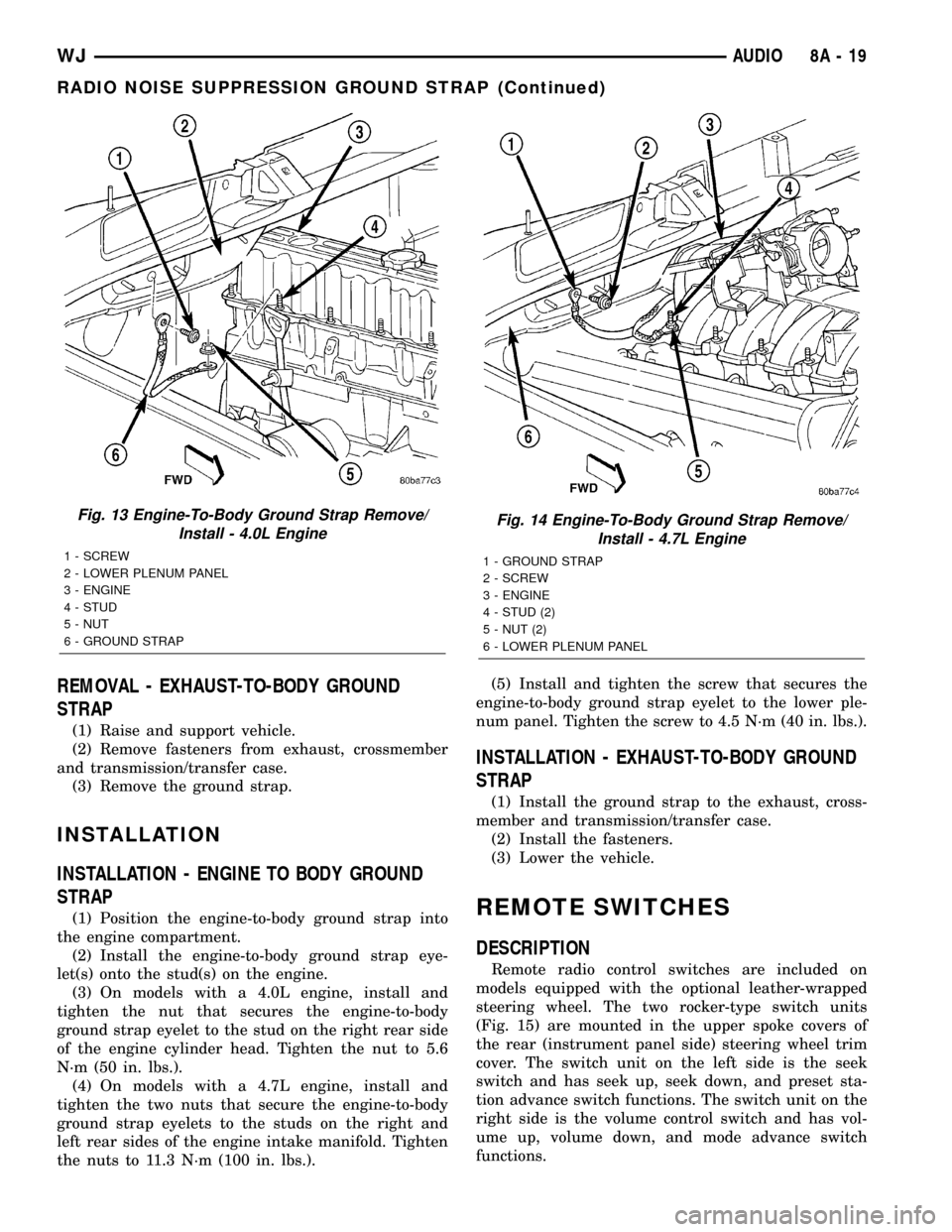
REMOVAL - EXHAUST-TO-BODY GROUND
STRAP
(1) Raise and support vehicle.
(2) Remove fasteners from exhaust, crossmember
and transmission/transfer case.
(3) Remove the ground strap.
INSTALLATION
INSTALLATION - ENGINE TO BODY GROUND
STRAP
(1) Position the engine-to-body ground strap into
the engine compartment.
(2) Install the engine-to-body ground strap eye-
let(s) onto the stud(s) on the engine.
(3) On models with a 4.0L engine, install and
tighten the nut that secures the engine-to-body
ground strap eyelet to the stud on the right rear side
of the engine cylinder head. Tighten the nut to 5.6
N´m (50 in. lbs.).
(4) On models with a 4.7L engine, install and
tighten the two nuts that secure the engine-to-body
ground strap eyelets to the studs on the right and
left rear sides of the engine intake manifold. Tighten
the nuts to 11.3 N´m (100 in. lbs.).(5) Install and tighten the screw that secures the
engine-to-body ground strap eyelet to the lower ple-
num panel. Tighten the screw to 4.5 N´m (40 in. lbs.).
INSTALLATION - EXHAUST-TO-BODY GROUND
STRAP
(1) Install the ground strap to the exhaust, cross-
member and transmission/transfer case.
(2) Install the fasteners.
(3) Lower the vehicle.
REMOTE SWITCHES
DESCRIPTION
Remote radio control switches are included on
models equipped with the optional leather-wrapped
steering wheel. The two rocker-type switch units
(Fig. 15) are mounted in the upper spoke covers of
the rear (instrument panel side) steering wheel trim
cover. The switch unit on the left side is the seek
switch and has seek up, seek down, and preset sta-
tion advance switch functions. The switch unit on the
right side is the volume control switch and has vol-
ume up, volume down, and mode advance switch
functions.
Fig. 13 Engine-To-Body Ground Strap Remove/
Install - 4.0L Engine
1 - SCREW
2 - LOWER PLENUM PANEL
3 - ENGINE
4 - STUD
5 - NUT
6 - GROUND STRAP
Fig. 14 Engine-To-Body Ground Strap Remove/
Install - 4.7L Engine
1 - GROUND STRAP
2 - SCREW
3 - ENGINE
4 - STUD (2)
5 - NUT (2)
6 - LOWER PLENUM PANEL
WJAUDIO 8A - 19
RADIO NOISE SUPPRESSION GROUND STRAP (Continued)
Page 307 of 2199
The chime warning system provides an audible
indication to the vehicle operator under the following
conditions:
²Fasten Seat Belt Warning- The Body Control
Module (BCM) chime tone generator will generate
repetitive chimes to announce that an input from the
seat belt switch indicates the driver side front seat
belt is not fastened. Unless the driver side front seat
belt is fastened, the chimes will continue to sound for
a duration of about six seconds each time the ignition
switch is turned to the On position or until the driver
side front seat belt is fastened.
²Head/Park Lights-On Warning- The BCM
chime tone generator will generate repetitive chimes
at a fast rate to announce that a Programmable
Communications Interface (PCI) data bus driver door
ajar message, along with hard wired inputs from the
headlamp switch indicate that the exterior lamps are
turned On with the driver side front door opened.
The chime will continue to sound until the exterior
lamps are turned Off, the driver side front door is
closed, or the ignition switch is turned to the On
position.
²Key-In-Ignition Warning- The BCM chime
tone generator will generate repetitive chimes at a
fast rate to announce that a PCI data bus driver door
ajar message received from the Driver Door Module
(DDM), along with hard wired inputs from the key-
in-ignition warning switch indicate that the key is in
the ignition cylinder with the driver side front door
opened and the ignition switch in the Off position.
The chime will continue to sound until the key is
removed from the ignition lock cylinder, the driver
side front door is closed, or the ignition switch is
turned to the On position.
²Overspeed Warning- The BCM chime tone
generator will generate repetitive chimes at a slowrate to announce that a PCI data bus vehicle speed
message received from the Powertrain Control Mod-
ule (PCM) indicates that the vehicle speed is above
120 kilometers-per-hour (75 miles-per-hour). The
chimes will continue to sound until the vehicle speed
is below 120 kilometers-per-hour (75 miles-per-hour).
This feature is only enabled on a BCM that has been
programmed with a Middle East Gulf Coast Country
(GCC) country code.
²Tactile Beep Support- The BCM chime tone
generator will generate a single beep each time a
PCI data bus tactile beep request message is received
from the Electronic Vehicle Information Center
(EVIC) or the Sentry Key Immobilizer Module
(SKIM). This beep provides an audible confirmation
that an EVIC button was completely depressed, or
that the optional Sentry Key Immobilizer System
(SKIS) is in the ªCustomer Learnº mode.
²Warning Beep Support- The BCM chime tone
generator will generate a short series of beeps each
time a PCI data bus warning beep request message
is received from the EVIC or the Electro-Mechanical
Instrument Cluster (EMIC). These beeps provide an
audible alert to the vehicle operator, of certain visual
warning indications displayed by the EVIC and/or
the EMIC.
The BCM provides chime service for all available
features in the chime warning system. The BCM
relies upon message inputs received from other mod-
ules over the PCI data bus network to provide chime
service for all of the remaining chime warning sys-
tem features.
The internal programming of the BCM determines
the priority of each chime tone request input that is
received, as well as the rate and duration of each
chime tone that is to be generated.
8B - 2 CHIME/BUZZERWJ
CHIME WARNING SYSTEM (Continued)