power socket JEEP GRAND CHEROKEE 2002 WJ / 2.G Workshop Manual
[x] Cancel search | Manufacturer: JEEP, Model Year: 2002, Model line: GRAND CHEROKEE, Model: JEEP GRAND CHEROKEE 2002 WJ / 2.GPages: 2199, PDF Size: 76.01 MB
Page 465 of 2199

CONDITION POSSIBLE CAUSES CORRECTION
FOG LAMPS DO NOT
ILLUMINATE1. Blown fuse for fog lamp. 1. Replace fuse. Refer to Electrical, Wiring
Information.
2. No Z1-ground at fog lamps. 2. Repair circuit ground. Refer to Electrical,
Wiring Information.
3. Faulty multifunction switch. 3. Refer to Electrical, Wiring Information.
4. Broken connector terminal or wire
splice in fog lamp circuit.4. Repair connector terminal or wire splice.
5. Defective or burned out bulb. 5. Replace bulb.
DAYTIME RUNNING LAMP
CONDITION POSSIBLE CAUSES CORRECTION
DAYTIME RUNNING LAMPS DO
NOT WORK1. Poor connection at DRL module. 1. Secure connector on DRL
module.
2. Parking brake engaged. 2. Disengage parking brake.
3. Parking brake circuit shorted to
ground.3. Check cluster telltale, refer to
Group 8W.
4. Headlamp circuit shorted to
ground.4. Refer to Group 8W.
5. Defective DRL relay. 5. Replace DRL relay.
6. Body controller not programed
with Canadian country code.6. Check country code.
7. DRL relay is missing. 7. Install DRL relay.
8. Blown fuse for DRL. 8. Replace fuse refer to Electrical,
Wiring Information.
Clicking or chattering when DRL is
on.1. Mechanical relay is installed in
the junction block.1. Ensure that the DRL relay is
installed in the proper socket in
junction block, and that no
mechanical relay exists in the low
beam socket.
DIAGNOSIS AND TESTING Ð HEADLAMP
WARNING: EYE PROTECTION SHOULD BE USED
WHEN SERVICING GLASS COMPONENTS. PER-
SONAL INJURY CAN RESULT.
CAUTION: Do not touch the glass of halogen bulbs
with fingers or other possibly oily surface, reduced
bulb life will result. Do not use bulbs other than
those indicated in the Bulb Application table. Dam-
age to lamp and/or Daytime Running Lamp Module
can result. Do not use fuses, circuit breakers or
relays having greater amperage value than indi-
cated on the fuse panel or in the Owners Manual.
Each vehicle is equipped with various lamp assem-
blies. A good power feed and ground are necessary forproper lighting operation. Grounding is provided by
the lamp socket when it comes in contact with the
metal body, or through a separate ground wire.
When changing lamp bulbs check the socket for
corrosion. If corrosion is present, clean it with a wire
brush and coat the inside of the socket lightly with
Mopar Multi-Purpose Grease or equivalent.
REMOVAL - BULB
(1) Remove the headlamp.
(2) Turn the bulb socket one quarter turn counter
clockwise.
(3) Remove the socket from lamp (Fig. 13).
(4) Remove the bulb from socket.
8L - 14 LAMPS/LIGHTING - EXTERIORWJ
HEADLAMP (Continued)
Page 483 of 2199

READING LAMP
DESCRIPTION
The overhead console in this vehicle is equipped
with two individual reading and courtesy lamps.Each
lamp has its own switch, bulb, reflector and lens; but
both lamps share a common lamp housing within the
overhead console.
The overhead console reading and courtesy lamps
operate on battery current that is provided at all
times, regardless of the ignition switch position. The
ground feed for the lamps is switched through the
integral reading and courtesy lamp switches or
through the door jamb switches.
The reading and courtesy lamp lenses and the
lamp housing and reflector unit are serviced only as
a unit with the overhead console housing.The reading
and courtesy lamp switches, bulb holders and wiring
are only available as part of the overhead console
wire harness.
For service of the reading and courtesy lamp bulbs,
(Refer to 8 - ELECTRICAL/LAMPS/LIGHTING -
INTERIOR/READING LAMP - REMOVAL). For diag-
nosis of the reading and courtesy lamps, refer to the
appropriate wiring information.
OPERATION
All reading and courtesy lamps located in the over-
head console are activated by the door jamb switches.
When all of the doors are closed, these lamps can be
individually activated by depressing the correspond-
ing lens. When any door is open, depressing the lamp
lenses to activate the lamp switches will not turn the
lamps off.
REMOVAL
(1) Remove the overhead console.
(2) Rotate the console until the bulb is visible (Fig.
2).
(3) Grasp the bulb and remove from the socket.
INSTALLATION
(1) Push the bulb into the bulb socket.
(2) Install the console on the headliner and roof
panel.
(3) Align the screw hole and install the screw.
TRANS RANGE INDICATOR
ILLUMINATION
DESCRIPTION
The Transmission Range Indicator Lamp, mounted
on the floor console, uses electroluminescent technol-ogy as the light source. This lamp requires a 120 volt
AC signal that is provided by a power converter
included as part of the assembly. The module is not
serviceable separately. Because of a potential shock
hazard, diagnostic testing of the lamp assembly
should be avoided. Refer to TRANSMISSION, Range
Selector Assembly Removal and Installation.
VANITY LAMP
REMOVAL
(1) Fold down the visor.
(2) Using a small flat blade, and staring at the
base of the lamp assembly, carefully pry the base of
the lamp from the visor.
(3) Disconnect the vanity lamp visor and remove
the lamp from the vehicle.
INSTALLATION
(1) Position the lamp at the visor and connect the
wire connector.
(2) Press the lamp in place.
Fig. 2 Overhead Console Reading Lamp Bulb
1 - BULB
8L - 32 LAMPS/LIGHTING - INTERIORWJ
Page 484 of 2199

MESSAGE SYSTEMS
TABLE OF CONTENTS
page page
OVERHEAD CONSOLE
DESCRIPTION..........................1
OPERATION............................1
STANDARD PROCEDURE
STANDARD PROCEDURE - MODULE LAMP
REPLACEMENT.......................1
STANDARD PROCEDURE - COURTESY
LAMP REPLACEMENT..................1
STANDARD PROCEDURE - MODULE LENS
REPLACEMENT.......................2
STANDARD PROCEDURE - ELECTRONIC
VEHICLE INFORMATION CENTER
PROGRAMMING.......................2
STANDARD PROCEDURE - COMPASS
DEMAGNETIZING......................4
STANDARD PROCEDURE - COMPASS
CALIBRATION.........................5
STANDARD PROCEDURE - COMPASS
VARIATION ADJUSTMENT................5
REMOVAL.............................5
INSTALLATION..........................6
SPECIAL TOOLS
OVERHEAD CONSOLE SYSTEMS.........6
ELECTRONIC VEHICLE INFO CENTER
DESCRIPTION..........................6OPERATION............................9
DIAGNOSIS AND TESTING - ELECTRONIC
VEHICLE INFORMATION CENTER.........9
STANDARD PROCEDURE - TIRE PRESSURE
SYSTEM TEST.......................10
REMOVAL.............................10
INSTALLATION.........................10
UNIVERSAL TRANSMITTER
DESCRIPTION.........................11
OPERATION...........................11
DIAGNOSIS AND TESTING - UNIVERSAL
TRANSMITTER.......................11
AMBIENT TEMP SENSOR
DESCRIPTION.........................12
OPERATION...........................12
DIAGNOSIS AND TESTING
DIAGNOSIS AND TESTING - AMBIENT
TEMPERATURE SENSOR...............12
DIAGNOSIS AND TESTING - AMBIENT
TEMPERATURE SENSOR CIRCUIT........12
REMOVAL.............................12
INSTALLATION.........................13
OVERHEAD CONSOLE
DESCRIPTION
An overhead console is standard factory-installed
equipment on this model. The overhead console
includes the Electronic Vehicle Information Center
(EVIC) and two reading and courtesy lamps (Fig. 1).
On vehicles equipped with a power sunroof option,
the overhead console also houses the power sunroof
switch between the two reading and courtesy lamps.
The overhead console is mounted with one screw and
two snap-clips to a molded plastic retainer bracket
located above the headliner. The retainer bracket is
secured with adhesive to the inside surface of the
roof panel.
Following are general descriptions of the major
components used in the overhead console. Refer to
Overhead Consolein Wiring Diagrams for complete
circuit diagrams.
OPERATION
See the owner's manual in the vehicle glove box for
more information on the use and operation of the
various overhead console features.
STANDARD PROCEDURE
STANDARD PROCEDURE - MODULE LAMP
REPLACEMENT
(1) Remove the overhead console (Refer to 8 -
ELECTRICAL/OVERHEAD CONSOLE - REMOV-
AL).
(2) Using a flat blade screwdriver twist out socket/
lamp (Fig. 2).
(3) Replace lamp(s) as necessary.
STANDARD PROCEDURE - COURTESY LAMP
REPLACEMENT
(1) Open hood, disconnect and isolate the negative
battery cable.
WJMESSAGE SYSTEMS 8M - 1
Page 485 of 2199

(2) Remove the overhead console from the head-
liner (Refer to 8 - ELECTRICAL/OVERHEAD CON-
SOLE - REMOVAL).(3) Remove the lamp and socket assembly from the
overhead console.
(4) Remove the lamp bulb by pulling it straight
out of its socket.
STANDARD PROCEDURE - MODULE LENS
REPLACEMENT
(1) Remove the overhead console (Refer to 8 -
ELECTRICAL/OVERHEAD CONSOLE - REMOV-
AL).
(2) Remove the electronics module from the over-
head console. Refer to the procedure in this section.
(3) Unsnap the lens from the module and replace
lens as necessary.
STANDARD PROCEDURE - ELECTRONIC
VEHICLE INFORMATION CENTER
PROGRAMMING
EVIC PROGRAMMING MODE
The Electronic Vehicle Information Center (EVIC)
provides the vehicle operator with a user interface,
which allows the selection of several optional cus-
tomer programmable electronic features to suit indi-
vidual preferences. The EVIC must be placed into its
programming mode in order to view or change the
programmable features. To enter the EVIC program-
ming mode and to view or change the selected pro-
grammable features options, proceed as follows:
(1) Turn the ignition switch to the On position.
(2) Depress and release the Menu push button.
The first item in the programmable features menu
list will appear in the EVIC display.
(3) Momentarily depress and release the Menu
push button to step through the programmable fea-
tures list. Each programmable feature and its cur-
rently selected option will appear on the EVIC
display in the sequence shown in the Programmable
Features list that follows.
(4) Momentarily depress and release the Step push
button to step through the available options for the
programmable feature being displayed.
(5) The option that last appears in the display
with a programmable feature before exiting the pro-
gramming mode, becomes the newly selected pro-
grammable feature option.
(6) The EVIC exits the programming mode and
returns to its normal operating mode when the C/T
push button is depressed or when the end of the pro-
grammable features menu list is reached, whichever
occurs first.
Fig. 1 Overhead Console
1 - POWER SUNROOF SWITCH (IF EQUIPPED)
2 - READING AND COURTESY LAMPS
3 - UNIVERSAL GARAGE DOOR OPENER PUSH BUTTONS (IF
EQUIPPED)
4 - SCREW
5 - ELECTRONIC VEHICLE INFORMATION CENTER PUSH
BUTTONS
Fig. 2 Top of Overhead Console
1 - OVERHEAD CONSOLE HOUSING
2 - EVIC MODULE
3 - ILLUMINATION LAMPS
4 - SCREWS (4)
8M - 2 MESSAGE SYSTEMSWJ
OVERHEAD CONSOLE (Continued)
Page 1495 of 2199

ADJUSTMENTS
STEERING GEAR
NOTE: Adjusting the steering gear in the vehicle is
not recommended. Remove gear from the vehicle
and drain the fluid. Then mount gear in a vise to
perform adjustments.
OVER-CENTER
(1) Rotate the stub shaft with Socket 8343 from
stop to stop and count the number of turns.
(2) Center the stub shaft by rotating it from the
stop 1/2 of the total amount of turns.
(3) Place torque wrench and Socket 8343 in a ver-
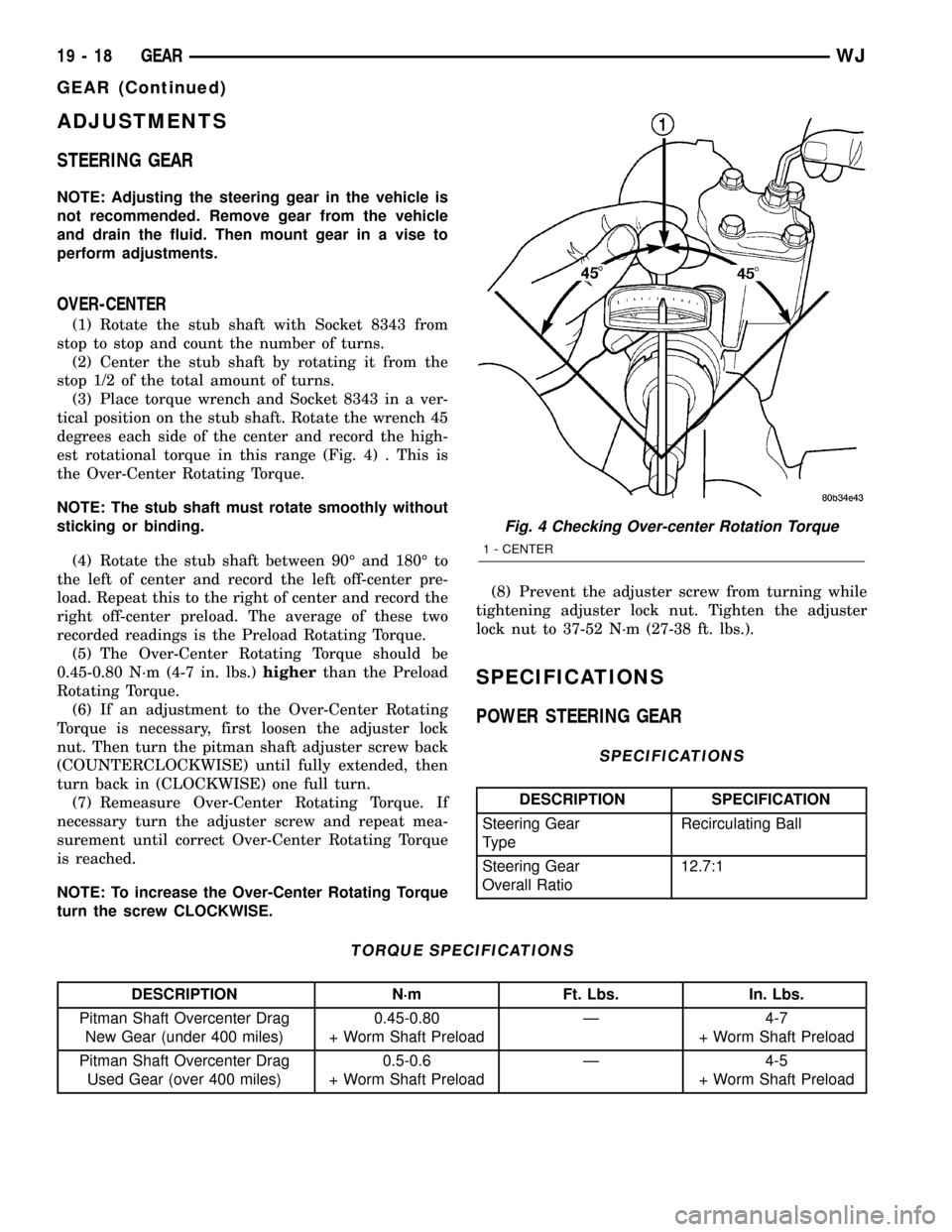
tical position on the stub shaft. Rotate the wrench 45
degrees each side of the center and record the high-
est rotational torque in this range (Fig. 4) . This is
the Over-Center Rotating Torque.
NOTE: The stub shaft must rotate smoothly without
sticking or binding.
(4) Rotate the stub shaft between 90É and 180É to
the left of center and record the left off-center pre-
load. Repeat this to the right of center and record the
right off-center preload. The average of these two
recorded readings is the Preload Rotating Torque.
(5) The Over-Center Rotating Torque should be
0.45-0.80 N´m (4-7 in. lbs.)higherthan the Preload
Rotating Torque.
(6) If an adjustment to the Over-Center Rotating
Torque is necessary, first loosen the adjuster lock
nut. Then turn the pitman shaft adjuster screw back
(COUNTERCLOCKWISE) until fully extended, then
turn back in (CLOCKWISE) one full turn.
(7) Remeasure Over-Center Rotating Torque. If
necessary turn the adjuster screw and repeat mea-
surement until correct Over-Center Rotating Torque
is reached.
NOTE: To increase the Over-Center Rotating Torque
turn the screw CLOCKWISE.(8) Prevent the adjuster screw from turning while
tightening adjuster lock nut. Tighten the adjuster
lock nut to 37-52 N´m (27-38 ft. lbs.).
SPECIFICATIONS
POWER STEERING GEAR
SPECIFICATIONS
DESCRIPTION SPECIFICATION
Steering Gear
TypeRecirculating Ball
Steering Gear
Overall Ratio12.7:1
TORQUE SPECIFICATIONS
DESCRIPTION N´m Ft. Lbs. In. Lbs.
Pitman Shaft Overcenter Drag
New Gear (under 400 miles)0.45-0.80
+ Worm Shaft PreloadÐ 4-7
+ Worm Shaft Preload
Pitman Shaft Overcenter Drag
Used Gear (over 400 miles)0.5-0.6
+ Worm Shaft PreloadÐ 4-5
+ Worm Shaft Preload
Fig. 4 Checking Over-center Rotation Torque
1 - CENTER
19 - 18 GEARWJ
GEAR (Continued)