replace crankshaft position sensor JEEP GRAND CHEROKEE 2002 WJ / 2.G Workshop Manual
[x] Cancel search | Manufacturer: JEEP, Model Year: 2002, Model line: GRAND CHEROKEE, Model: JEEP GRAND CHEROKEE 2002 WJ / 2.GPages: 2199, PDF Size: 76.01 MB
Page 328 of 2199
(3) Disconnect the instrument panel wire harness
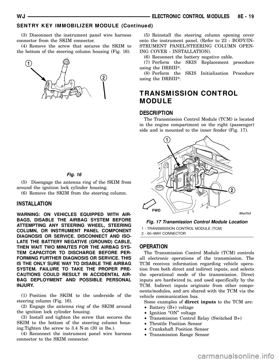
connector from the SKIM connector.
(4) Remove the screw that secures the SKIM to
the bottom of the steering column housing (Fig. 16).
(5) Disengage the antenna ring of the SKIM from
around the ignition lock cylinder housing.
(6) Remove the SKIM from the steering column.
INSTALLATION
WARNING: ON VEHICLES EQUIPPED WITH AIR-
BAGS, DISABLE THE AIRBAG SYSTEM BEFORE
ATTEMPTING ANY STEERING WHEEL, STEERING
COLUMN, OR INSTRUMENT PANEL COMPONENT
DIAGNOSIS OR SERVICE. DISCONNECT AND ISO-
LATE THE BATTERY NEGATIVE (GROUND) CABLE,
THEN WAIT TWO MINUTES FOR THE AIRBAG SYS-
TEM CAPACITOR TO DISCHARGE BEFORE PER-
FORMING FURTHER DIAGNOSIS OR SERVICE. THIS
IS THE ONLY SURE WAY TO DISABLE THE AIRBAG
SYSTEM. FAILURE TO TAKE THE PROPER PRE-
CAUTIONS COULD RESULT IN ACCIDENTAL AIR-
BAG DEPLOYMENT AND POSSIBLE PERSONAL
INJURY.
(1) Position the SKIM to the underside of the
steering column (Fig. 16).
(2) Engage the antenna ring of the SKIM around
the ignition lock cylinder housing.
(3) Install and tighten the screw that secures the
SKIM to the bottom of the steering column hous-
ing.Tighten the screw to 3.4 N´m (30 in lbs.).
(4) Reconnect the instrument panel wire harness
connector to the SKIM connector.(5) Reinstall the steering column opening cover
onto the instrument panel. (Refer to 23 - BODY/IN-
STRUMENT PANEL/STEERING COLUMN OPEN-
ING COVER - INSTALLATION).
(6) Reconnect the battery negative cable.
(7) Perform the SKIS Replacement procedure
using the DRBIIIt.
(8) Perform the SKIS Initialization Procedure
using the DRBIIIt.
TRANSMISSION CONTROL
MODULE
DESCRIPTION
The Transmission Control Module (TCM) is located
in the engine compartment on the right (passenger)
side and is mounted to the inner fender (Fig. 17).
OPERATION
The Transmission Control Module (TCM) controls
all electronic operations of the transmission. The
TCM receives information regarding vehicle opera-
tion from both direct and indirect inputs, and selects
the operational mode of the transmission. Direct
inputs are hardwired to, and used specifically by the
TCM. Indirect inputs originate from other compo-
nents/modules, and are shared with the TCM via the
vehicle communication bus.
Some examples ofdirect inputsto the TCM are:
²Battery (B+) voltage
²Ignition ªONº voltage
²Transmission Control Relay (Switched B+)
²Throttle Position Sensor
²Crankshaft Position Sensor
²Transmission Range Sensor
Fig. 16
Fig. 17 Transmission Control Module Location
1 - TRANSMISSION CONTROL MODULE (TCM)
2 - 60±WAY CONNECTOR
WJELECTRONIC CONTROL MODULES 8E - 19
SENTRY KEY IMMOBILIZER MODULE (Continued)
Page 399 of 2199
The ignition system is controlled by the powertrain
control module (PCM) on all engines.
The ignition system consists of:
²Spark Plugs
²Ignition Coil(s)
²Powertrain Control Module (PCM)
²Crankshaft Position Sensor
²Camshaft Position Sensor
²The MAP, TPS, IAC and ECT also have an effect
on the control of the ignition system.
SPECIFICATIONS
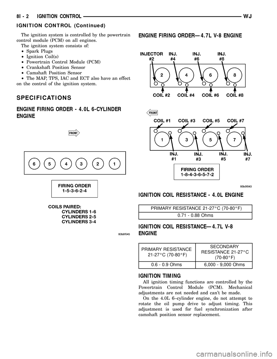
ENGINE FIRING ORDER - 4.0L 6-CYLINDER
ENGINEENGINE FIRING ORDERÐ4.7L V-8 ENGINE
IGNITION COIL RESISTANCE - 4.0L ENGINE
PRIMARY RESISTANCE 21-27ÉC (70-80ÉF)
0.71 - 0.88 Ohms
IGNITION COIL RESISTANCEÐ4.7L V-8
ENGINE
PRIMARY RESISTANCE
21-27ÉC (70-80ÉF)SECONDARY
RESISTANCE 21-27ÉC
(70-80ÉF)
0.6 - 0.9 Ohms 6,000 - 9,000 Ohms
IGNITION TIMING
All ignition timing functions are controlled by the
Powertrain Control Module (PCM). Mechanical
adjustments are not needed and can't be made.
On the 4.0L 6±cylinder engine, do not attempt to
rotate the oil pump drive to adjust timing. This
adjustment is used for fuel synchronization after
camshaft position sensor replacement.
8I - 2 IGNITION CONTROLWJ
IGNITION CONTROL (Continued)
Page 447 of 2199

Control Module (PCM) over the Programmable Com-
munications Interface (PCI) data bus. The tachome-
ter is an air core magnetic unit that receives battery
current on the instrument cluster electronic circuit
board through the fused ignition switch output (run-
start) circuit whenever the ignition switch is in the
On or Start positions. The cluster is programmed to
move the gauge needle back to the low end of the
scale after the ignition switch is turned to the Off
position. The instrument cluster circuitry controls
the gauge needle position and provides the following
features:
²Engine Speed Message- Each time the cluster
receives an engine speed message from the PCM it
will calculate the correct engine speed reading and
position the gauge needle at that speed position on
the gauge scale. The cluster will receive a new
engine speed message and reposition the gauge
pointer accordingly about every 86 milliseconds. The
gauge needle will continue to be positioned at the
actual engine speed position on the gauge scale until
the ignition switch is turned to the Off position.
²Communication Error- If the cluster fails to
receive an engine speed message, it will hold the
gauge needle at the last indication for about six sec-
onds, or until the ignition switch is turned to the Off
position, whichever occurs first. If a new engine
speed message is not received after about six sec-
onds, the gauge needle will return to the far left
(low) end of the scale.
²Actuator Test- Each time the cluster is put
through the actuator test, the gauge needle will be
swept across the entire gauge scale and back in order
to confirm the functionality of the gauge and the
cluster control circuitry.
The PCM continually monitors the crankshaft posi-
tion sensor to determine the engine speed, then
sends the proper engine speed messages to the
instrument cluster. For further diagnosis of the
tachometer or the instrument cluster circuitry that
controls the gauge, (Refer to 8 - ELECTRICAL/IN-
STRUMENT CLUSTER - DIAGNOSIS AND TEST-
ING). For proper diagnosis of the crankshaft position
sensor, the PCM, the PCI data bus, or the electronic
message inputs to the instrument cluster that control
the tachometer, a DRBIIItscan tool is required.
Refer to the appropriate diagnostic information.
TRANS TEMP INDICATOR
DESCRIPTION
A transmission over-temperature indicator is stan-
dard equipment on all gasoline engine instrument
clusters. The transmission over-temperature indica-
tor is located near the lower right corner of theinstrument cluster, to the right of the speedometer.
The transmission over-temperature indicator consists
of the words ªTRANS OVER TEMPº imprinted on an
amber lens. The lens is located behind a cutout in
the opaque layer of the instrument cluster overlay.
The dark outer layer of the overlay prevents the indi-
cator from being clearly visible when it is not illumi-
nated. The words ªTRANS OVER TEMPº appear
silhouetted against an amber field through the trans-
lucent outer layer of the overlay when the indicator
is illuminated from behind by a replaceable incandes-
cent bulb and bulb holder unit located on the instru-
ment cluster electronic circuit board. The
transmission over-temperature indicator lens is ser-
viced as a unit with the instrument cluster lens, hood
and mask unit.
OPERATION
The transmission over-temperature indicator gives
an indication to the vehicle operator when the trans-
mission fluid temperature is excessive, which may
lead to accelerated transmission component wear or
failure. This indicator is controlled by a transistor on
the instrument cluster electronic circuit board based
upon cluster programming and electronic messages
received by the cluster over the Programmable Com-
munications Interface (PCI) data bus. These mes-
sages are sent by the Powertrain Control Module
(PCM) or by the Transmission Control Module
(TCM), depending on the model of the automatic
transmission. The transmission over-temperature
indicator bulb is completely controlled by the instru-
ment cluster logic circuit, and that logic will only
allow this indicator to operate when the instrument
cluster receives a battery current input on the fused
ignition switch output (run-start) circuit. Therefore,
the indicator will always be off when the ignition
switch is in any position except On or Start. The bulb
only illuminates when it is provided a path to ground
by the instrument cluster transistor. The instrument
cluster will turn on the transmission over-tempera-
ture indicator for the following reasons:
²Bulb Test- Each time the ignition switch is
turned to the On position the transmission over-tem-
perature indicator is illuminated for about three sec-
onds as a bulb test.
²Trans Over-Temp Indicator Lamp-On Mes-
sage- Each time the cluster receives a trans over-
temp indicator lamp-on message from the PCM or
TCM indicating that the transmission fluid tempera-
ture is 135É C (275É F) or higher, the transmission
over-temperature indicator will be illuminated. The
indicator remains illuminated until the cluster
receives a trans over-temp indicator lamp-off mes-
sage from the PCM or TCM, or until the ignition
8J - 32 INSTRUMENT CLUSTERWJ
TACHOMETER (Continued)
Page 1256 of 2199

INSTALLATION
CAUTION: When installing the engine into a vehicle
equipped with an automatic transmission, be care-
ful not to damage the trigger wheel on the engine
flywheel.
(1) Attach a lifting device to the engine and lower
the engine into the engine compartment. For easier
installation, it may be necessary to remove the
engine mount bracket as an aid in alignment of the
engine to the transmission.
(2) Align the transmission torque converter hous-
ing with the engine.
(3) Loosely install the converter housing lower
bolts and install the next higher bolt and nut on each
side.
(4) Tighten all 4 bolts finger tight.
(5) Install the engine mount brackets (if removed).
(6) Lower the engine and engine mount brackets
onto the engine compartment cushions. Install the
bolts and finger tighten the nuts.
(7) Remove the engine lifting device.
(8) Raise and support the vehicle.
(9) Install the remaining engine flywheel/converter
housing bolts. Tighten all bolts to 38 N´m (28 ft. lbs.)
torque.
(10) Install the converter-to-drive plate bolts.
(11) Ensure the installation reference marks are
aligned.
(12) Install the engine flywheel/converter housing
access cover.
(13) Install the exhaust pipe support and tighten
the screw.
(14) Install the engine bending brace (Refer to 9 -
ENGINE/ENGINE BLOCK/STRUCT SUPPORT -
INSTALLATION).
(15) Tighten the engine mount-to-bracket bolts.
(16) Connect the vehicle speed sensor wire connec-
tions and tighten the screws.
(17) Connect the exhaust pipe to the manifold.
(18) Install the engine starter motor (Refer to 8 -
ELECTRICAL/STARTING/STARTER MOTOR -
INSTALLATION).
(19) Connect the wires to the engine starter motor
solenoid.
(20) Lower the vehicle.
(21) Connect all the vacuum hoses and wire con-
nectors identified during engine removal.
(22) Remove protective caps from the power steer-
ing hoses.
(23) Connect the hoses to the fittings at the steer-
ing gear. Tighten the nut to 52 N´m (38 ft. lbs.)
torque.
(24) Fill the pump reservoir with fluid.(25) Inspect the fuel supply line o-ring(s) and
replace if necessary. Connect fuel supply line to injec-
tior rail and verify connection by pulling outward on
the line.
(26) Install the fuel line bracket to the intake
manifold.
(27) Connect the coil rail electrical connectors and
oil pressure switch connector.
(28) Connect the following electrical connectors:
²Power steering pressure switch
²Coolant temperature sensor
²Six (6) fuel injector connectors
²Intake air temperature sensor
²Throttle position sensor
²Map sensor
²Crankshaft position sensor
²Oxygen sensor
²Camshaft position sensor
²Generator connector and B+ terminal wire
(29) Connect all previously removed vacuum hoses.
(30) Connect the body ground strap.
(31) Install the throttle, transmission line pres-
sure, and speed control cables to their mounting
bracket and connect them to the throttle body.
(32) Connect the heater hoses at the engine ther-
mostat housing and water pump.
(33) Install the fan assembly (Refer to 7 - COOL-
ING/ENGINE/RADIATOR FAN - INSTALLATION).
(34) Place the fan shroud in position over the fan.
(35) Install the radiator (Refer to 7 - COOLING/
ENGINE/RADIATOR - INSTALLATION).
(36) Connect the service valves to the A/C com-
pressor ports, if equipped with A/C.
(37) Charge the air conditioner system (Refer to 24
- HEATING & AIR CONDITIONING/PLUMBING -
STANDARD PROCEDURE).
(38) Connect the radiator hoses and automatic
transmission fluid cooler pipes, if equipped.
(39) Install the fan shroud to the radiator or radi-
ator/condenser (if equipped with A/C).
(40) Install upper radiator support.
(41) Connect the upper radiator hose and tighten
the clamp.
(42) Connect the lower radiator hose and tighten
the clamp.
(43) Fill crankcase with engine oil. (Refer to
LUBRICATION & MAINTENANCE/FLUID CAPACI-
TIES - SPECIFICATIONS) for correct capacities.
(44) Fill the cooling system with reusable coolant
or new coolant (Refer to 7 - COOLING - STANDARD
PROCEDURE).
(45) Align the hood to the scribe marks. Install the
hood.
(46) Install the air cleaner assembly.
(47) Install the battery and connect the battery
cable.
WJENGINE - 4.0L 9 - 13
ENGINE - 4.0L (Continued)
Page 1274 of 2199
REMOVAL
REMOVAL - CAMSHAFT BEARINGS
The camshaft rotates within four steel-shelled,
babbitt-lined bearings that are pressed into the cyl-
inder block and then line reamed. The camshaft
bearing bores and bearing diameters are not the
same size. They are stepped down in 0.254 mm
(0.010 inch) increments from the front bearing (larg-
est) to the rear bearing (smallest). This permits eas-
ier removal and installation of the camshaft. The
camshaft bearings are pressure lubricated. Camshaft
end play is maintained by the thrust plate.
(1) Remove the camshaft (Refer to 9 - ENGINE/
ENGINE BLOCK/CAMSHAFT & BEARINGS (IN
BLOCK) - REMOVAL).
NOTE: It is not advisable to attempt to replace cam-
shaft bearings unless special removal and installa-
tion tools are available, such as recommended tool
8544 Camshaft Bushing Remover Installer.
(2) Using Special tool 8544 Camshaft Bushing
Remover Installer, remove the camshaft bearings.
REMOVAL - CAMSHAFT
WARNING: THE COOLANT IN A RECENTLY OPER-
ATED ENGINE IS HOT AND PRESSURIZED.RELEASE THE PRESSURE BEFORE REMOVING
THE DRAIN COCK, CAP AND DRAIN PLUGS.
(1) Disconnect negative cable from battery.
(2) Drain the cooling system (Refer to 7 - COOL-
ING - STANDARD PROCEDURE).
(3) Remove the radiator (Refer to 7 - COOLING/
ENGINE/RADIATOR - REMOVAL) and condenser
(Refer to 24 - HEATING & AIR CONDITIONING/
PLUMBING/A/C CONDENSER - REMOVAL), if
equipped with A/C.
(4) Remove the engine cylinder head cover (Refer
to 9 - ENGINE/CYLINDER HEAD/CYLINDER
HEAD COVER(S) - REMOVAL).
(5) Remove the rocker arms, bridges and pivots
(Refer to 9 - ENGINE/CYLINDER HEAD/ROCKER
ARM / ADJUSTER ASSY - REMOVAL).
(6) Remove the push rods.
(7) Remove the engine cylinder head and gasket
(Refer to 9 - ENGINE/CYLINDER HEAD - REMOV-
AL).
(8) Remove the hydraulic valve tappets from the
engine cylinder block (Refer to 9 - ENGINE/ENGINE
BLOCK/HYDRAULIC LIFTERS (CAM IN BLOCK) -
REMOVAL).
(9) Remove the vibration damper (Refer to 9 -
ENGINE/ENGINE BLOCK/VIBRATION DAMPER -
REMOVAL).
(10) Remove the timing case cover (Refer to 9 -
ENGINE/VALVE TIMING/TIMING BELT / CHAIN
COVER(S) - REMOVAL).
(11) Rotate the crankshaft until the crankshaft
sprocket timing mark is aligned on centerline with
the camshaft sprocket timing mark (Fig. 32).
(12) Remove the timing chain and sprockets (Refer
to 9 - ENGINE/VALVE TIMING/TIMING BELT/
CHAIN AND SPROCKETS - REMOVAL).
(13) Remove the front bumper and/or grille, as
required.
(14) Remove the two thrust plate retaining screws,
thrust plate and camshaft (Fig. 31).
INSPECTION
INSPECTION - CAMSHAFT BEARINGS
(1) Inspect the bearing journals for uneven wear
pattern or finish.
(2) Inspect the bearings for wear.
INSPECTION - CAMSHAFT
(1) Inspect the cam lobes for wear.
(2) Inspect the camshaft position sensor drive gear
for wear.
(3) If the camshaft appears to have been rubbing
against the thrust washer, examine the oil pressure
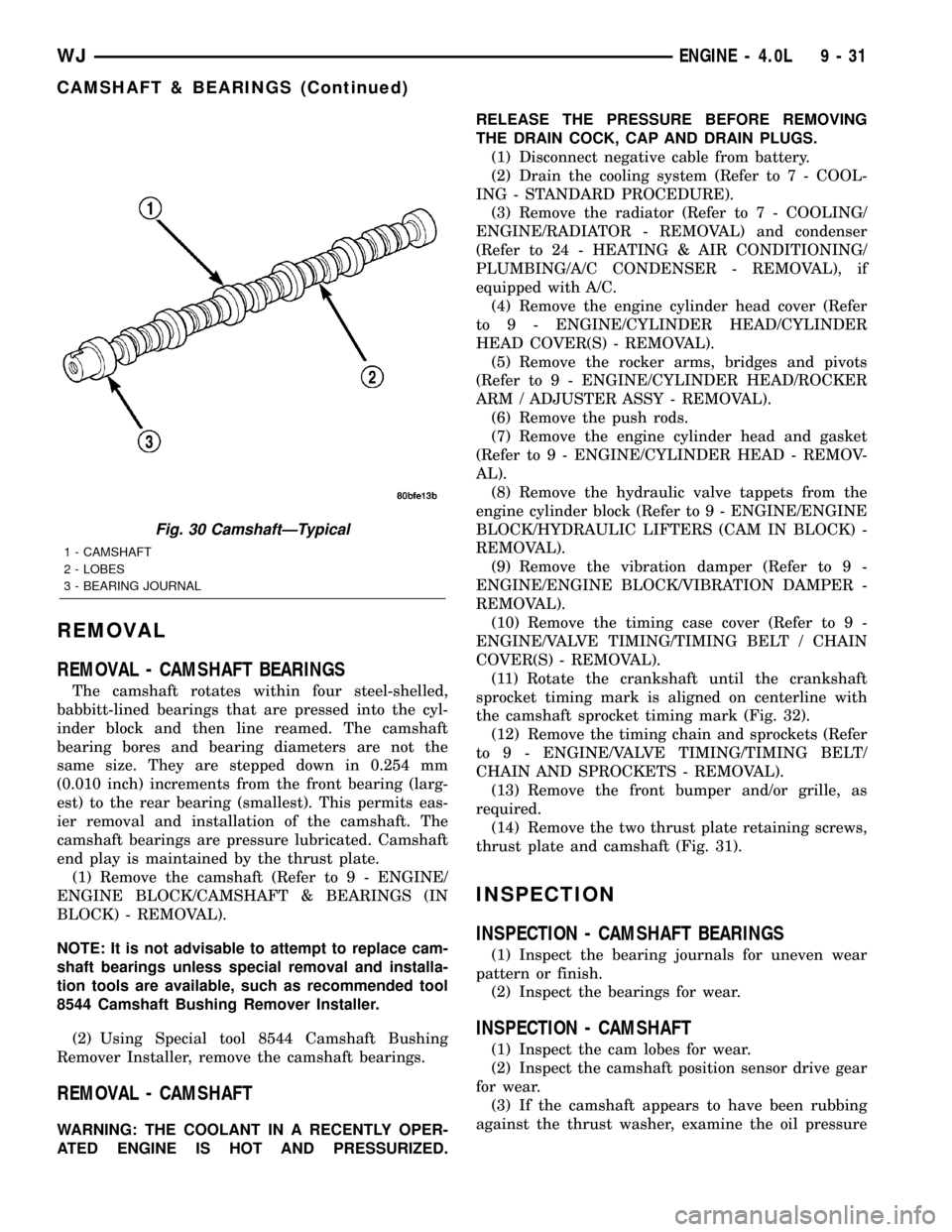
Fig. 30 CamshaftÐTypical
1 - CAMSHAFT
2 - LOBES
3 - BEARING JOURNAL
WJENGINE - 4.0L 9 - 31
CAMSHAFT & BEARINGS (Continued)
Page 1354 of 2199
Bearing
MarkSIZE USED WITH
JOURNAL SIZE
.025 US.025 mm 50.983-50.967 mm
(.001 in.) (2.0073-2.0066 in.)
Std.STANDARD 50.992-51.008 mm
(2.0076-2.0082 in.)
.250 US.250 mm 50.758-50.742 mm
(.010 in.) (1.9984-1.9978 in.)
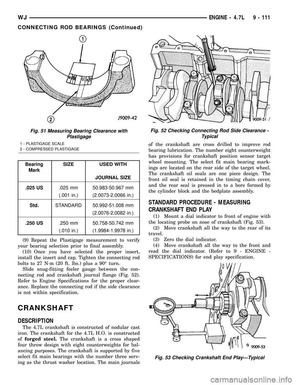
(9) Repeat the Plastigage measurement to verify
your bearing selection prior to final assembly.
(10) Once you have selected the proper insert,
install the insert and cap. Tighten the connecting rod
bolts to 27 N´m (20 ft. lbs.) plus a 90É turn.
Slide snug-fitting feeler gauge between the con-
necting rod and crankshaft journal flange (Fig. 52).
Refer to Engine Specifications for the proper clear-
ance. Replace the connecting rod if the side clearance
is not within specification.
CRANKSHAFT
DESCRIPTION
The 4.7L crankshaft is constructed of nodular cast
iron. The crankshaft for the 4.7L H.O. is constructed
offorged steel.The crankshaft is a cross shaped
four throw design with eight counterweights for bal-
ancing purposes. The crankshaft is supported by five
select fit main bearings with the number three serv-
ing as the thrust washer location. The main journalsof the crankshaft are cross drilled to improve rod
bearing lubrication. The number eight counterweight
has provisions for crankshaft position sensor target
wheel mounting. The select fit main bearing mark-
ings are located on the rear side of the target wheel.
The crankshaft oil seals are one piece design. The
front oil seal is retained in the timing chain cover,
and the rear seal is pressed in to a bore formed by
the cylinder block and the bedplate assembly.
STANDARD PROCEDURE - MEASURING
CRANKSHAFT END PLAY
(1) Mount a dial indicator to front of engine with
the locating probe on nose of crankshaft (Fig. 53).
(2) Move crankshaft all the way to the rear of its
travel.
(3) Zero the dial indicator.
(4) Move crankshaft all the way to the front and
read the dial indicator. (Refer to 9 - ENGINE -
SPECIFICATIONS) for end play specification.
Fig. 51 Measuring Bearing Clearance with
Plastigage
1 - PLASTIGAGE SCALE
2 - COMPRESSED PLASTIGAGE
Fig. 52 Checking Connecting Rod Side Clearance -
Typical
Fig. 53 Checking Crankshaft End PlayÐTypical
WJENGINE - 4.7L 9 - 111
CONNECTING ROD BEARINGS (Continued)
Page 1358 of 2199
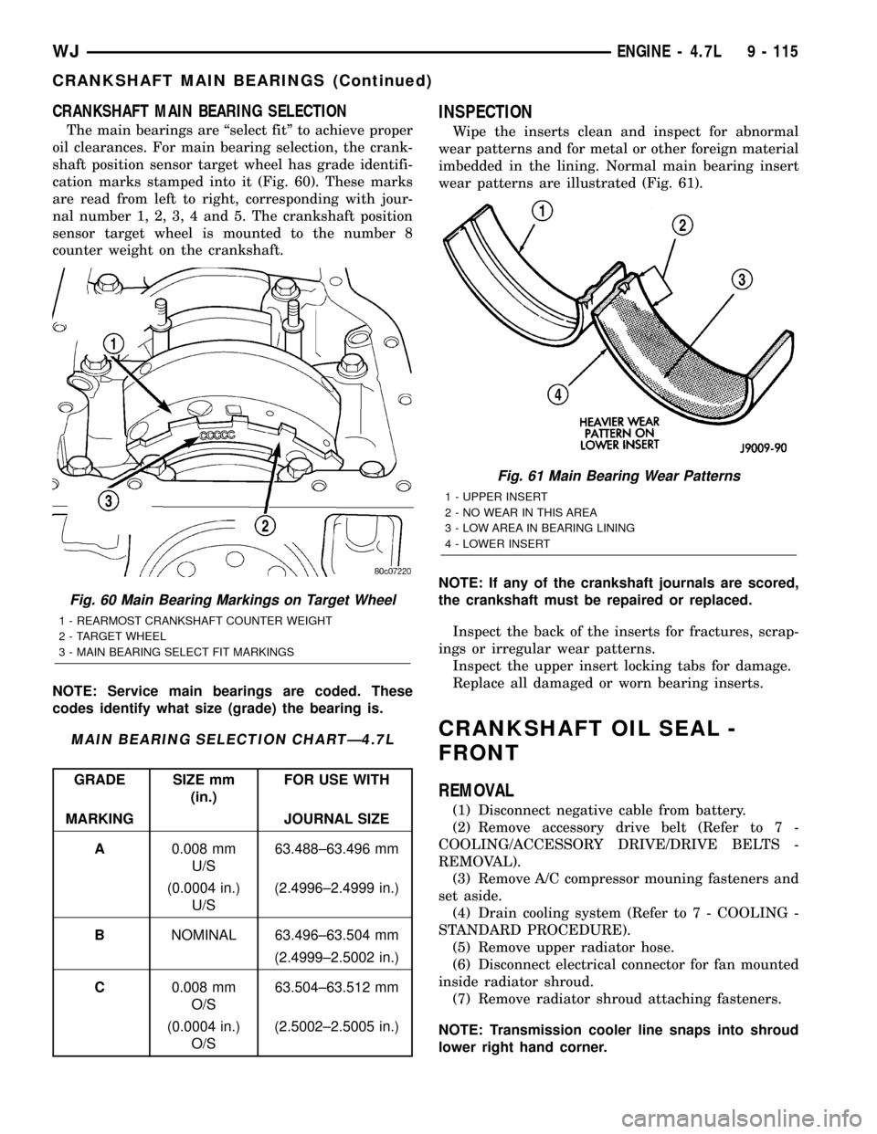
CRANKSHAFT MAIN BEARING SELECTION
The main bearings are ªselect fitº to achieve proper
oil clearances. For main bearing selection, the crank-
shaft position sensor target wheel has grade identifi-
cation marks stamped into it (Fig. 60). These marks
are read from left to right, corresponding with jour-
nal number 1, 2, 3, 4 and 5. The crankshaft position
sensor target wheel is mounted to the number 8
counter weight on the crankshaft.
NOTE: Service main bearings are coded. These
codes identify what size (grade) the bearing is.
MAIN BEARING SELECTION CHARTÐ4.7L
GRADE SIZE mm
(in.)FOR USE WITH
MARKING JOURNAL SIZE
A0.008 mm
U/S63.488±63.496 mm
(0.0004 in.)
U/S(2.4996±2.4999 in.)
BNOMINAL 63.496±63.504 mm
(2.4999±2.5002 in.)
C0.008 mm
O/S63.504±63.512 mm
(0.0004 in.)
O/S(2.5002±2.5005 in.)
INSPECTION
Wipe the inserts clean and inspect for abnormal
wear patterns and for metal or other foreign material
imbedded in the lining. Normal main bearing insert
wear patterns are illustrated (Fig. 61).
NOTE: If any of the crankshaft journals are scored,
the crankshaft must be repaired or replaced.
Inspect the back of the inserts for fractures, scrap-
ings or irregular wear patterns.
Inspect the upper insert locking tabs for damage.
Replace all damaged or worn bearing inserts.
CRANKSHAFT OIL SEAL -
FRONT
REMOVAL
(1) Disconnect negative cable from battery.
(2) Remove accessory drive belt (Refer to 7 -
COOLING/ACCESSORY DRIVE/DRIVE BELTS -
REMOVAL).
(3) Remove A/C compressor mouning fasteners and
set aside.
(4) Drain cooling system (Refer to 7 - COOLING -
STANDARD PROCEDURE).
(5) Remove upper radiator hose.
(6) Disconnect electrical connector for fan mounted
inside radiator shroud.
(7) Remove radiator shroud attaching fasteners.
NOTE: Transmission cooler line snaps into shroud
lower right hand corner.
Fig. 60 Main Bearing Markings on Target Wheel
1 - REARMOST CRANKSHAFT COUNTER WEIGHT
2 - TARGET WHEEL
3 - MAIN BEARING SELECT FIT MARKINGS
Fig. 61 Main Bearing Wear Patterns
1 - UPPER INSERT
2 - NO WEAR IN THIS AREA
3 - LOW AREA IN BEARING LINING
4 - LOWER INSERT
WJENGINE - 4.7L 9 - 115
CRANKSHAFT MAIN BEARINGS (Continued)
Page 1392 of 2199
INSPECTION
Inspect the following components:
²Sprockets for excessive tooth wear. Some tooth
markings are normal and not a cause for sprocket
replacement.
²Idler sprocket assembly bushing and shaft for
excessive wear.
²Idler sprocket assembly spline joint. The joint
should be tight with no backlash or axial movement.
²Chain guides and tensioner arms. Replace these
parts if grooving in plastic face is more than 1 mm
(0.039 in.) deep. If plastic face is severely grooved or
melted, the tensioner lube jet may be clogged. The
tensioner should be replaced.
²secondary chain tensioner piston and ratcheting
device. Inspect for evidence of heavy contact between
tensioner piston and tensioner arm. If this condition
exist the tensioner and tensioner arm should be
replaced.
²Primary chain tensioner plastic faces. Replace as
required (Fig. 127).
INSTALLATION
(1) Using a vise, lightly compress the secondary
chain tensioner piston until the piston step is flush
with the tensioner body. Using a pin or suitable tool,
release ratchet pawl by pulling pawl back against
spring force through access hole on side of tensioner.
While continuing to hold pawl back, Push ratchet
device to approximately 2 mm from the tensioner
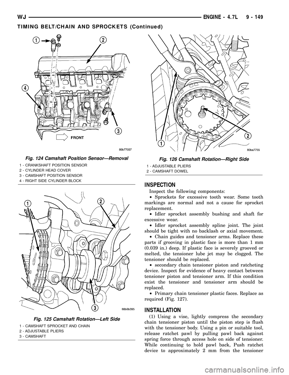
Fig. 124 Camshaft Position SensorÐRemoval
1 - CRANKSHAFT POSITION SENSOR
2 - CYLINDER HEAD COVER
3 - CAMSHAFT POSITION SENSOR
4 - RIGHT SIDE CYLINDER BLOCK
Fig. 125 Camshaft RotationÐLeft Side
1 - CAMSHAFT SPROCKET AND CHAIN
2 - ADJUSTABLE PLIERS
3 - CAMSHAFT
Fig. 126 Camshaft RotationÐRight Side
1 - ADJUSTABLE PLIERS
2 - CAMSHAFT DOWEL
WJENGINE - 4.7L 9 - 149
TIMING BELT/CHAIN AND SPROCKETS (Continued)
Page 1461 of 2199
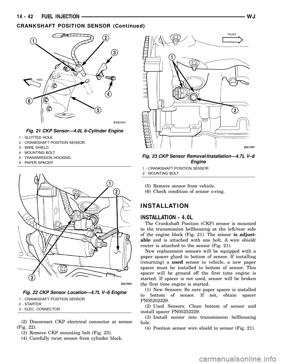
(2) Disconnect CKP electrical connector at sensor
(Fig. 22).
(3) Remove CKP mounting bolt (Fig. 23).
(4) Carefully twist sensor from cylinder block.(5) Remove sensor from vehicle.
(6) Check condition of sensor o-ring.
INSTALLATION
INSTALLATION - 4.0L
The Crankshaft Position (CKP) sensor is mounted
to the transmission bellhousing at the left/rear side
of the engine block (Fig. 21). The sensoris adjust-
ableand is attached with one bolt. A wire shield/
router is attached to the sensor (Fig. 21).
New replacement sensors will be equipped with a
paper spacer glued to bottom of sensor. If installing
(returning) ausedsensor to vehicle, a new paper
spacer must be installed to bottom of sensor. This
spacer will be ground off the first time engine is
started. If spacer is not used, sensor will be broken
the first time engine is started.
(1) New Sensors: Be sure paper spacer is installed
to bottom of sensor. If not, obtain spacer
PN05252229.
(2) Used Sensors: Clean bottom of sensor and
install spacer PN05252229.
(3) Install sensor into transmission bellhousing
hole.
(4) Position sensor wire shield to sensor (Fig. 21).
Fig. 21 CKP SensorÐ4.0L 6-Cylinder Engine
1 - SLOTTED HOLE
2 - CRANKSHAFT POSITION SENSOR
3 - WIRE SHIELD
4 - MOUNTING BOLT
5 - TRANSMISSION HOUSING
6 - PAPER SPACER
Fig. 22 CKP Sensor LocationÐ4.7L V±8 Engine
1 - CRANKSHAFT POSITION SENSOR
2-STARTER
3 - ELEC. CONNECTOR
Fig. 23 CKP Sensor Removal/InstallationÐ4.7L V±8
Engine
1 - CRANKSHAFT POSITION SENSOR
2 - MOUNTING BOLT
14 - 42 FUEL INJECTIONWJ
CRANKSHAFT POSITION SENSOR (Continued)
Page 1717 of 2199
(5) Carefully insert converter in oil pump. Then
rotate converter back and forth until fully seated in
pump gears.
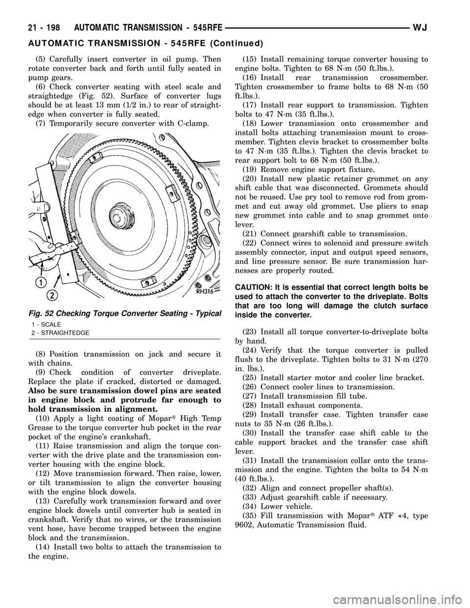
(6) Check converter seating with steel scale and
straightedge (Fig. 52). Surface of converter lugs
should be at least 13 mm (1/2 in.) to rear of straight-
edge when converter is fully seated.
(7) Temporarily secure converter with C-clamp.
(8) Position transmission on jack and secure it
with chains.
(9) Check condition of converter driveplate.
Replace the plate if cracked, distorted or damaged.
Also be sure transmission dowel pins are seated
in engine block and protrude far enough to
hold transmission in alignment.
(10) Apply a light coating of MopartHigh Temp
Grease to the torque converter hub pocket in the rear
pocket of the engine's crankshaft.
(11) Raise transmission and align the torque con-
verter with the drive plate and the transmission con-
verter housing with the engine block.
(12) Move transmission forward. Then raise, lower,
or tilt transmission to align the converter housing
with the engine block dowels.
(13) Carefully work transmission forward and over
engine block dowels until converter hub is seated in
crankshaft. Verify that no wires, or the transmission
vent hose, have become trapped between the engine
block and the transmission.
(14) Install two bolts to attach the transmission to
the engine.(15) Install remaining torque converter housing to
engine bolts. Tighten to 68 N´m (50 ft.lbs.).
(16) Install rear transmission crossmember.
Tighten crossmember to frame bolts to 68 N´m (50
ft.lbs.).
(17) Install rear support to transmission. Tighten
bolts to 47 N´m (35 ft.lbs.).
(18) Lower transmission onto crossmember and
install bolts attaching transmission mount to cross-
member. Tighten clevis bracket to crossmember bolts
to 47 N´m (35 ft.lbs.). Tighten the clevis bracket to
rear support bolt to 68 N´m (50 ft.lbs.).
(19) Remove engine support fixture.
(20) Install new plastic retainer grommet on any
shift cable that was disconnected. Grommets should
not be reused. Use pry tool to remove rod from grom-
met and cut away old grommet. Use pliers to snap
new grommet into cable and to snap grommet onto
lever.
(21) Connect gearshift cable to transmission.
(22) Connect wires to solenoid and pressure switch
assembly connector, input and output speed sensors,
and line pressure sensor. Be sure transmission har-
nesses are properly routed.
CAUTION: It is essential that correct length bolts be
used to attach the converter to the driveplate. Bolts
that are too long will damage the clutch surface
inside the converter.
(23) Install all torque converter-to-driveplate bolts
by hand.
(24) Verify that the torque converter is pulled
flush to the driveplate. Tighten bolts to 31 N´m (270
in. lbs.).
(25) Install starter motor and cooler line bracket.
(26) Connect cooler lines to transmission.
(27) Install transmission fill tube.
(28) Install exhaust components.
(29) Install transfer case. Tighten transfer case
nuts to 35 N´m (26 ft.lbs.).
(30) Install the transfer case shift cable to the
cable support bracket and the transfer case shift
lever.
(31) Install the transmission collar onto the trans-
mission and the engine. Tighten the bolts to 54 N´m
(40 ft.lbs.).
(32) Align and connect propeller shaft(s).
(33) Adjust gearshift cable if necessary.
(34) Lower vehicle.
(35) Fill transmission with MopartATF +4, type
9602, Automatic Transmission fluid.
Fig. 52 Checking Torque Converter Seating - Typical
1 - SCALE
2 - STRAIGHTEDGE
21 - 198 AUTOMATIC TRANSMISSION - 545RFEWJ
AUTOMATIC TRANSMISSION - 545RFE (Continued)