Rear hub JEEP GRAND CHEROKEE 2003 WJ / 2.G Workshop Manual
[x] Cancel search | Manufacturer: JEEP, Model Year: 2003, Model line: GRAND CHEROKEE, Model: JEEP GRAND CHEROKEE 2003 WJ / 2.GPages: 2199, PDF Size: 76.01 MB
Page 127 of 2199
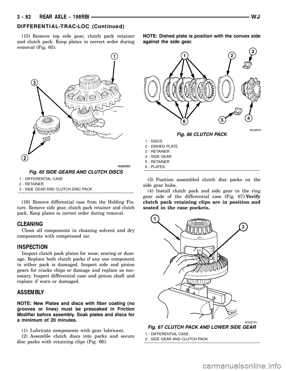
(15) Remove top side gear, clutch pack retainer
and clutch pack. Keep plates in correct order during
removal (Fig. 65).
(16)
Remove differential case from the Holding Fix-
ture. Remove side gear, clutch pack retainer and clutch
pack. Keep plates in correct order during removal.
CLEANING
Clean all components in cleaning solvent and dry
components with compressed air.
INSPECTION
Inspect clutch pack plates for wear, scoring or dam-
age. Replace both clutch packs if any one component
in either pack is damaged. Inspect side and pinion
gears for cracks chips or damage and replace as nec-
essary. Inspect differential case and pinion shaft and
replace if worn or damaged.
ASSEMBLY
NOTE: New Plates and discs with fiber coating (no
grooves or lines) must be presoaked in Friction
Modifier before assembly. Soak plates and discs for
a minimum of 20 minutes.
(1) Lubricate components with gear lubricant.
(2) Assemble clutch discs into packs and secure
disc packs with retaining clips (Fig. 66).NOTE: Dished plate is position with the convex side
against the side gear.
(3) Position assembled clutch disc packs on the
side gear hubs.
(4) Install clutch pack and side gear in the ring
gear side of the differential case (Fig. 67).Verify
clutch pack retaining clips are in position and
seated in the case pockets.
Fig. 65 SIDE GEARS AND CLUTCH DISCS
1 - DIFFERENTIAL CASE
2 - RETAINER
3 - SIDE GEAR AND CLUTCH DISC PACK
Fig. 66 CLUTCH PACK
1 - DISCS
2 - DISHED PLATE
3 - RETAINER
4 - SIDE GEAR
5 - RETAINER
6 - PLATES
Fig. 67 CLUTCH PACK AND LOWER SIDE GEAR
1 - DIFFERENTIAL CASE
2 - SIDE GEAR AND CLUTCH PACK
3 - 82 REAR AXLE - 198RBIWJ
DIFFERENTIAL-TRAC-LOC (Continued)
Page 167 of 2199
damaged. Inspect side gears and pinions. Replace
any gear that is worn, cracked, chipped or damaged.
Inspect differential case and pinion shaft. Replace if
worn or damaged.
NOTE: New Plates and discs with fiber coating (no
grooves or lines) must be presoaked in Friction
Modifier before assembly. Soak plates and discs for
a minimum of 20 minutes.
(1) Lubricate each component with gear lubricant
before assembly.
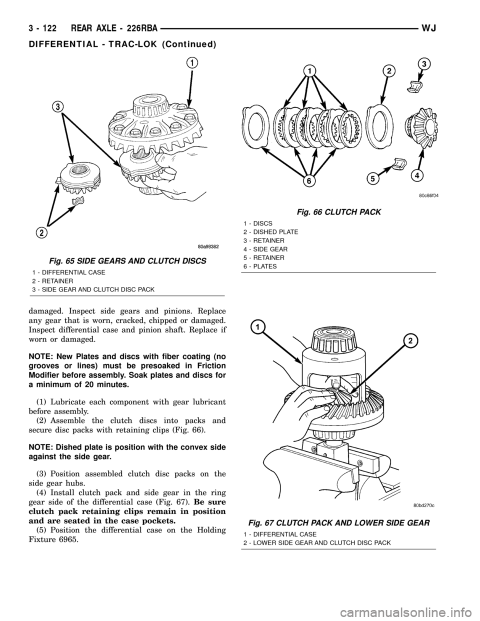
(2) Assemble the clutch discs into packs and
secure disc packs with retaining clips (Fig. 66).
NOTE: Dished plate is position with the convex side
against the side gear.
(3) Position assembled clutch disc packs on the
side gear hubs.
(4) Install clutch pack and side gear in the ring
gear side of the differential case (Fig. 67).Be sure
clutch pack retaining clips remain in position
and are seated in the case pockets.
(5) Position the differential case on the Holding
Fixture 6965.
Fig. 65 SIDE GEARS AND CLUTCH DISCS
1 - DIFFERENTIAL CASE
2 - RETAINER
3 - SIDE GEAR AND CLUTCH DISC PACK
Fig. 66 CLUTCH PACK
1 - DISCS
2 - DISHED PLATE
3 - RETAINER
4 - SIDE GEAR
5 - RETAINER
6 - PLATES
Fig. 67 CLUTCH PACK AND LOWER SIDE GEAR
1 - DIFFERENTIAL CASE
2 - LOWER SIDE GEAR AND CLUTCH DISC PACK
3 - 122 REAR AXLE - 226RBAWJ
DIFFERENTIAL - TRAC-LOK (Continued)
Page 207 of 2199
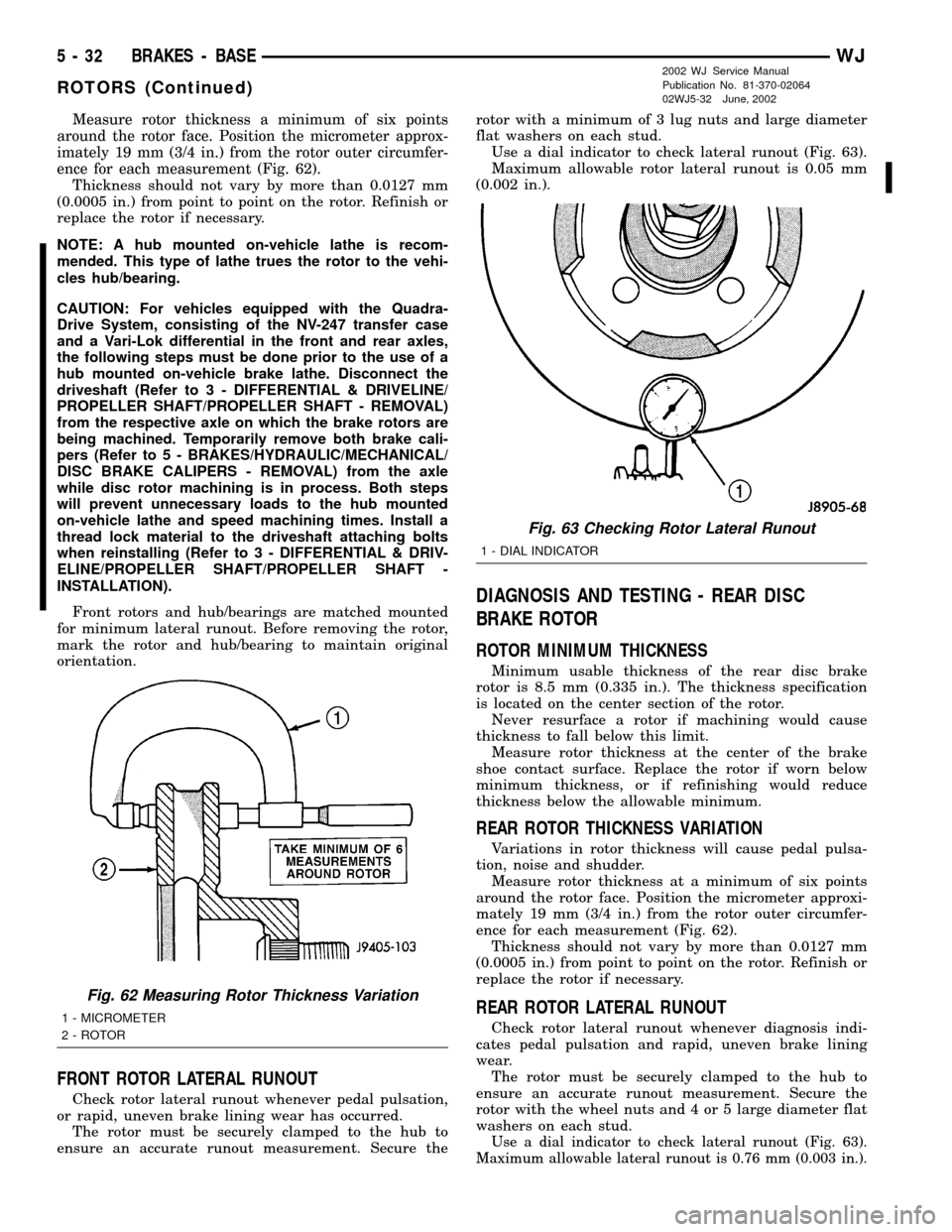
Measure rotor thickness a minimum of six points
around the rotor face. Position the micrometer approx-
imately 19 mm (3/4 in.) from the rotor outer circumfer-
ence for each measurement (Fig. 62).
Thickness should not vary by more than 0.0127 mm
(0.0005 in.) from point to point on the rotor. Refinish or
replace the rotor if necessary.
NOTE: A hub mounted on-vehicle lathe is recom-
mended. This type of lathe trues the rotor to the vehi-
cles hub/bearing.
CAUTION: For vehicles equipped with the Quadra-
Drive System, consisting of the NV-247 transfer case
and a Vari-Lok differential in the front and rear axles,
the following steps must be done prior to the use of a
hub mounted on-vehicle brake lathe. Disconnect the
driveshaft (Refer to 3 - DIFFERENTIAL & DRIVELINE/
PROPELLER SHAFT/PROPELLER SHAFT - REMOVAL)
from the respective axle on which the brake rotors are
being machined. Temporarily remove both brake cali-
pers (Refer to 5 - BRAKES/HYDRAULIC/MECHANICAL/
DISC BRAKE CALIPERS - REMOVAL) from the axle
while disc rotor machining is in process. Both steps
will prevent unnecessary loads to the hub mounted
on-vehicle lathe and speed machining times. Install a
thread lock material to the driveshaft attaching bolts
when reinstalling (Refer to 3 - DIFFERENTIAL & DRIV-
ELINE/PROPELLER SHAFT/PROPELLER SHAFT -
INSTALLATION).
Front rotors and hub/bearings are matched mounted
for minimum lateral runout. Before removing the rotor,
mark the rotor and hub/bearing to maintain original
orientation.
FRONT ROTOR LATERAL RUNOUT
Check rotor lateral runout whenever pedal pulsation,
or rapid, uneven brake lining wear has occurred.
The rotor must be securely clamped to the hub to
ensure an accurate runout measurement. Secure therotor with a minimum of 3 lug nuts and large diameter
flat washers on each stud.
Use a dial indicator to check lateral runout (Fig. 63).
Maximum allowable rotor lateral runout is 0.05 mm
(0.002 in.).
DIAGNOSIS AND TESTING - REAR DISC
BRAKE ROTOR
ROTOR MINIMUM THICKNESS
Minimum usable thickness of the rear disc brake
rotor is 8.5 mm (0.335 in.). The thickness specification
is located on the center section of the rotor.
Never resurface a rotor if machining would cause
thickness to fall below this limit.
Measure rotor thickness at the center of the brake
shoe contact surface. Replace the rotor if worn below
minimum thickness, or if refinishing would reduce
thickness below the allowable minimum.
REAR ROTOR THICKNESS VARIATION
Variations in rotor thickness will cause pedal pulsa-
tion, noise and shudder.
Measure rotor thickness at a minimum of six points
around the rotor face. Position the micrometer approxi-
mately 19 mm (3/4 in.) from the rotor outer circumfer-
ence for each measurement (Fig. 62).
Thickness should not vary by more than 0.0127 mm
(0.0005 in.) from point to point on the rotor. Refinish or
replace the rotor if necessary.
REAR ROTOR LATERAL RUNOUT
Check rotor lateral runout whenever diagnosis indi-
cates pedal pulsation and rapid, uneven brake lining
wear.
The rotor must be securely clamped to the hub to
ensure an accurate runout measurement. Secure the
rotor with the wheel nuts and 4 or 5 large diameter flat
washers on each stud.
Use a dial indicator to check lateral runout (Fig. 63).
Maximum allowable lateral runout is 0.76 mm (0.003 in.).
Fig. 62 Measuring Rotor Thickness Variation
1 - MICROMETER
2 - ROTOR
Fig. 63 Checking Rotor Lateral Runout
1 - DIAL INDICATOR
5 - 32 BRAKES - BASEWJ
ROTORS (Continued)
2002 WJ Service Manual
Publication No. 81-370-02064
02WJ5-32 June, 2002
Page 208 of 2199
STANDARD PROCEDURE - DISC ROTOR
MACHINING
CAUTION: For vehicles equipped with the Quadra-
Drive System, consisting of the NV-247 transfer case
and a Vari-Lok differential in the front and rear axles,
the following steps must be done prior to the use of a
hub mounted on-vehicle brake lathe. Disconnect the
driveshaft (Refer to 3 - DIFFERENTIAL & DRIVELINE/
PROPELLER SHAFT/PROPELLER SHAFT - REMOVAL)
from the respective axle on which the brake rotors are
being machined. Temporarily remove both brake cali-
pers (Refer to 5 - BRAKES/HYDRAULIC/MECHANICAL/
DISC BRAKE CALIPERS - REMOVAL) from the axle
while disc rotor machining is in process. Both steps
will prevent unnecessary loads to the hub mounted
on-vehicle lathe and speed machining times. Install a
thread lock material to the driveshaft attaching bolts
when reinstalling (Refer to 3 - DIFFERENTIAL & DRIV-
ELINE/PROPELLER SHAFT/PROPELLER SHAFT -
INSTALLATION).
NOTE: A hub mounted on-vehicle lathe is recom-
mended. This type of lathe trues the rotor to the vehi-
cles hub/bearing.
The disc brake rotor can be machined if scored or
worn. The lathe must machine both sides of the rotor
simultaneously with dual cutter heads. The rotor
mounting surface must be clean before placing on the
lathe. Equipment capable of machining only one side at
a time may produce a tapered rotor.
CAUTION: Brake rotors that do not meet minimum
thickness specifications before or after machining
must be replaced.
REMOVAL
REMOVAL - FRONT DISC BRAKE ROTOR
NOTE: Front rotors and hub/bearings are matched
mounted for minimum lateral runout. Before removing
the rotor, mark the rotor and hub/bearing to maintain
original orientation.
(1) Raise and support the vehicle.
(2) Remove wheel and tire assembly.
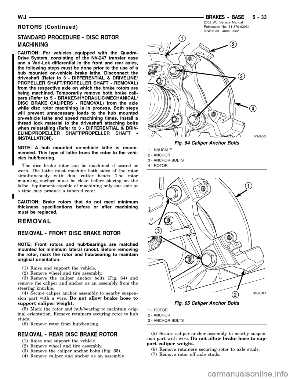
(3) Remove the caliper anchor bolts (Fig. 64) and
remove the caliper and anchor as an assembly from the
steering knuckle.
(4) Secure caliper anchor assembly to nearby suspen-
sion part with a wire.Do not allow brake hose to
support caliper weight.
(5) Mark the rotor and hub/bearing to maintain orig-
inal orientation. Remove retainers securing rotor to hub
studs.
(6) Remove rotor from hub/bearing.
REMOVAL - REAR DISC BRAKE ROTOR
(1) Raise and support the vehicle.
(2) Remove wheel and tire assembly.
(3) Remove the caliper anchor bolts (Fig. 65).
(4) Remove caliper and anchor as an assembly.(5) Secure caliper anchor assembly to nearby suspen-
sion part with wire.Do not allow brake hose to sup-
port caliper weight.
(6) Remove retainers securing rotor to axle studs.
(7) Remove rotor off axle studs.
Fig. 64 Caliper Anchor Bolts
1 - KNUCKLE
2 - ANCHOR
3 - ANCHOR BOLTS
4 - ROTOR
Fig. 65 Caliper Anchor Bolts
1 - ROTOR
2 - ANCHOR
3 - ANCHOR BOLTS
WJBRAKES - BASE 5 - 33
ROTORS (Continued)
2002 WJ Service Manual
Publication No. 81-370-02064
02WJ5-33 June, 2002
Page 209 of 2199
INSTALLATION
INSTALLATION - FRONT DISC BRAKE ROTOR
NOTE: If a new rotor is installed it must be match
mounted to the hub/bearing.
(1) Install rotor on hub studs in its original loca-
tion.
(2) Install the caliper anchor assembly on the
knuckle. Install anchor bolts and tighten to 90-115
N´m (66-85 ft. lbs.).
(3) Install wheel and tire assembly.
(4) Remove support and lower the vehicle.
(5) Pump brake pedal to seat caliper pistons and
brake shoes. Do not move vehicle until firm brake
pedal is obtained.
INSTALLATION - REAR DISC BRAKE ROTOR
(1) Install rotor on axle studs.
(2) Install the caliper anchor assembly.
(3) Install anchor bolts and tighten to 90-115 N´m
(66-85 ft. lbs.).
(4) Install wheel and tire assembly.
(5) Remove support and lower the vehicle.
(6) Pump brake pedal until caliper pistons and
brake shoes are seated.
PARKING BRAKE
OPERATION
The parking brakes operated by a automatic ten-
sioner mechanism built into the hand lever and cable
system. The front cable is connected to the hand
lever and the equalizer. The rear cables attached to
the equalizer and the parking brake shoe actuator.
A set of drum type brake shoes are used for park-
ing brakes. The shoes are mounted to the rear disc
brake adaptor. The parking brake drum is integrated
into the rear disc brake rotor.
Parking brake cable adjustment is controlled by an
automatic tensioner mechanism. The only adjust-
ment if necessary is to the park brake shoes if the
linings are worn.
DIAGNOSIS AND TESTING - PARKING BRAKE
NOTE: Parking brake adjustment is controlled by an
automatic cable tensioner and does not require
adjustment. The only adjustment that may be nec-
essary would be to the park brake shoes if they are
worn.
The parking brake switch is in circuit with the red
warning lamp in the dash. The switch will cause the
lamp to illuminate only when the parking brakes are
applied. If the lamp remains on after parking brake
release, the switch or wires are faulty.
If the red lamp comes on a fault has occurred in
the front or rear brake hydraulic system.
If the red warning lamp and yellow warning lamp
come on, the electronic brake distribution may be at
fault.
In most cases, the actual cause of an improperly
functioning parking brake (too loose/too tight/won't
hold), can be traced to a parking brake component.
NOTE: The leading cause of improper parking brake
operation, is excessive clearance between the park-
ing brake shoes and the shoe braking surface.
Excessive clearance is a result of lining and/or
drum wear, drum surface machined oversize.
Excessive parking brake lever travel (sometimes
described as a loose lever or too loose condition), is
the result of worn brake shoes, improper brake shoe
adjustment, or improperly assembled brake parts.
A too loose condition can also be caused by inoper-
ative or improperly assembled parking brake shoe
parts.
A condition where the parking brakes do not hold,
will most probably be due to a wheel brake compo-
nent.
Items to look for when diagnosing a parking brake
problem, are:
²Brake shoe wear
²Drum surface (in rear rotor) machined oversize
²Front cable not secured to lever
²Rear cable not attached to actuator
²Rear cable seized
²Parking brake lever not seated
²Parking brake lever bind
5 - 34 BRAKES - BASEWJ
ROTORS (Continued)
Page 214 of 2199
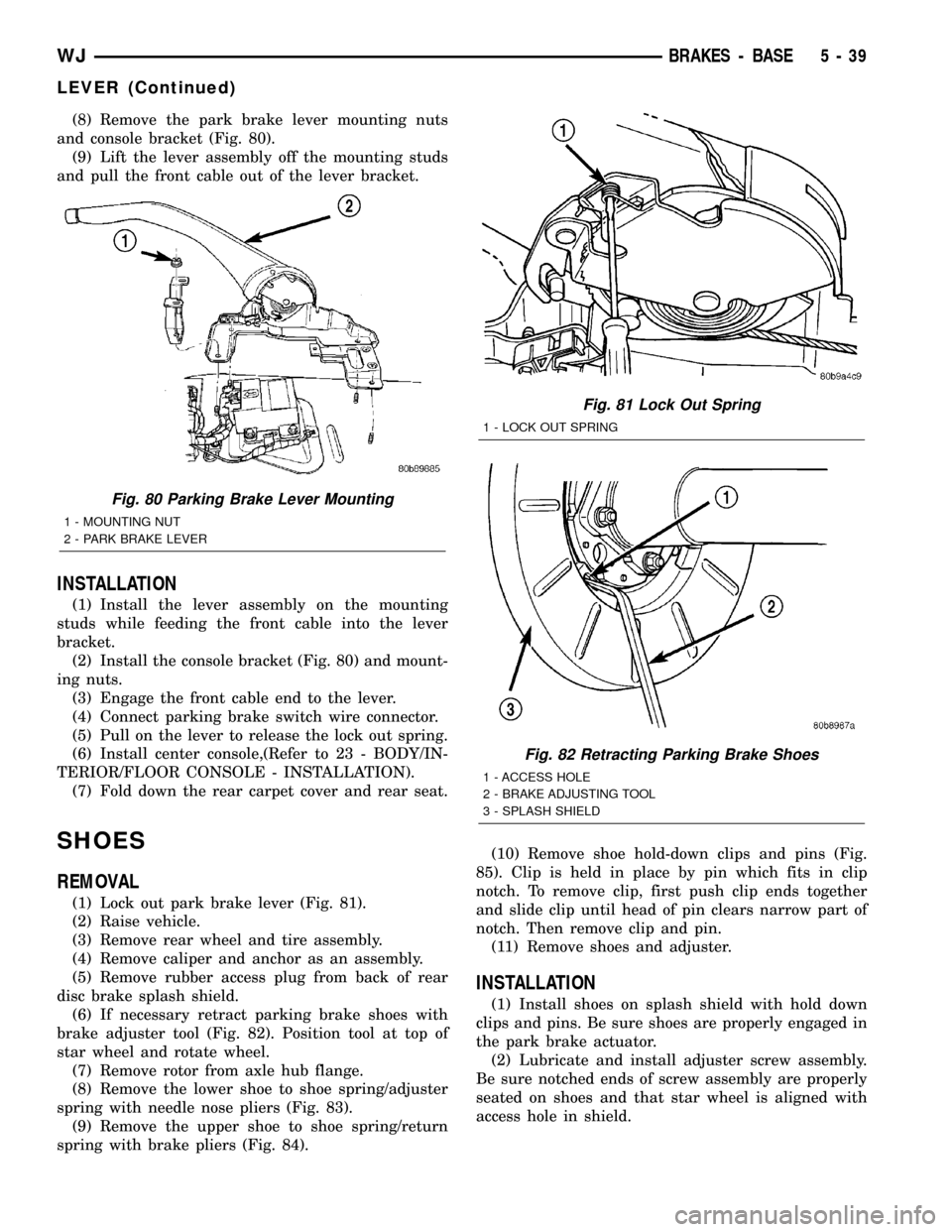
(8) Remove the park brake lever mounting nuts
and console bracket (Fig. 80).
(9) Lift the lever assembly off the mounting studs
and pull the front cable out of the lever bracket.
INSTALLATION
(1) Install the lever assembly on the mounting
studs while feeding the front cable into the lever
bracket.
(2) Install the console bracket (Fig. 80) and mount-
ing nuts.
(3) Engage the front cable end to the lever.
(4) Connect parking brake switch wire connector.
(5) Pull on the lever to release the lock out spring.
(6) Install center console,(Refer to 23 - BODY/IN-
TERIOR/FLOOR CONSOLE - INSTALLATION).
(7) Fold down the rear carpet cover and rear seat.
SHOES
REMOVAL
(1) Lock out park brake lever (Fig. 81).
(2) Raise vehicle.
(3) Remove rear wheel and tire assembly.
(4) Remove caliper and anchor as an assembly.
(5) Remove rubber access plug from back of rear
disc brake splash shield.
(6) If necessary retract parking brake shoes with
brake adjuster tool (Fig. 82). Position tool at top of
star wheel and rotate wheel.
(7) Remove rotor from axle hub flange.
(8) Remove the lower shoe to shoe spring/adjuster
spring with needle nose pliers (Fig. 83).
(9) Remove the upper shoe to shoe spring/return
spring with brake pliers (Fig. 84).(10) Remove shoe hold-down clips and pins (Fig.
85). Clip is held in place by pin which fits in clip
notch. To remove clip, first push clip ends together
and slide clip until head of pin clears narrow part of
notch. Then remove clip and pin.
(11) Remove shoes and adjuster.
INSTALLATION
(1) Install shoes on splash shield with hold down
clips and pins. Be sure shoes are properly engaged in
the park brake actuator.
(2) Lubricate and install adjuster screw assembly.
Be sure notched ends of screw assembly are properly
seated on shoes and that star wheel is aligned with
access hole in shield.
Fig. 80 Parking Brake Lever Mounting
1 - MOUNTING NUT
2 - PARK BRAKE LEVER
Fig. 81 Lock Out Spring
1 - LOCK OUT SPRING
Fig. 82 Retracting Parking Brake Shoes
1 - ACCESS HOLE
2 - BRAKE ADJUSTING TOOL
3 - SPLASH SHIELD
WJBRAKES - BASE 5 - 39
LEVER (Continued)
Page 273 of 2199
CAUTION: When installing the serpentine accessory
drive belt, belt must be routed correctly. If not,
engine may overheat due to water pump rotating in
wrong direction.
(6) Refill cooling system (Refer to 7 - COOLING -
STANDARD PROCEDURE).
(7) Connect negative battery cable.
(8) Start and warm the engine. Check for leaks.
WATER PUMP - 4.0L
DESCRIPTION
CAUTION: All 4.0L 6-cylinder engines are equipped
with a reverse (counterclockwise) rotating water
pump and thermal viscous fan drive assembly.
REVERSE is stamped or imprinted on the cover of
the viscous fan drive and inner side of the fan. The
letter R is stamped into the back of the water pump
impeller. Engines from previous model years,
depending upon application, may have been
equipped with a forward (clockwise) rotating water
pump. Installation of the wrong water pump or vis-
cous fan drive will cause engine over heating.
A centrifugal water pump circulates coolant
through the water jackets, passages, intake manifold,
radiator core, cooling system hoses and heater core.
The pump is driven from the engine crankshaft by a
single serpentine drive belt.
The water pump impeller is pressed onto the rear
of a shaft that rotates in bearings pressed into the
housing. The housing has two small holes to allow
seepage to escape. The water pump seals are lubri-
cated by the antifreeze in the coolant mixture. No
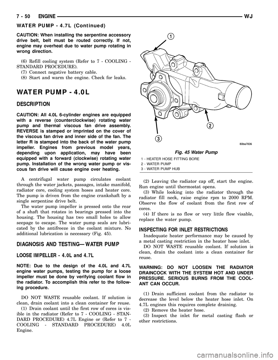
additional lubrication is necessary (Fig. 45).
DIAGNOSIS AND TESTINGÐWATER PUMP
LOOSE IMPELLER - 4.0L and 4.7L
NOTE: Due to the design of the 4.0L and 4.7L
engine water pumps, testing the pump for a loose
impeller must be done by verifying coolant flow in
the radiator. To accomplish this refer to the follow-
ing procedure.
DO NOT WASTE reusable coolant. If solution is
clean, drain coolant into a clean container for reuse.
(1) Drain coolant until the first row of cores is vis-
ible in the radiator (Refer to 7 - COOLING - STAN-
DARD PROCEDURE) 4.7L Engine or (Refer to 7 -
COOLING - STANDARD PROCEDURE) 4.0L
Engine.(2) Leaving the radiator cap off, start the engine.
Run engine until thermostat opens.
(3) While looking into the radiator through the
radiator fill neck, raise engine rpm to 2000 RPM.
Observe the flow of coolant from the first row of
cores.
(4) If there is no flow or very little flow visable,
replace the water pump.
INSPECTING FOR INLET RESTRICTIONS
Inadequate heater performance may be caused by
a metal casting restriction in the heater hose inlet.
DO NOT WASTE reusable coolant. If solution is
clean, drain the coolant into a clean container for
reuse.
WARNING: DO NOT LOOSEN THE RADIATOR
DRAINCOCK WITH THE SYSTEM HOT AND UNDER
PRESSURE. SERIOUS BURNS FROM THE COOL-
ANT CAN OCCUR.
(1) Drain sufficient coolant from the radiator to
decrease the level below the heater hose inlet. On
4.7L engines this requires complete draining.
(2) Remove the heater hose.
(3) Inspect the inlet for metal casting flash or
other restrictions.
Fig. 45 Water Pump
1 - HEATER HOSE FITTING BORE
2 - WATER PUMP
3 - WATER PUMP HUB
7 - 50 ENGINEWJ
WATER PUMP - 4.7L (Continued)
Page 274 of 2199
NOTE: On 4.0L engines remove the pump from the
engine before removing restriction to prevent con-
tamination of the coolant with debris. . On 4.7L
engine remove the fitting from the timing chain
cover, If the restriction is in the timing chain cover,
remove the timing chain cover.
REMOVAL
CAUTION: If the water pump is replaced because of
mechanical damage, the fan blades and viscous fan
drive should also be inspected. These components
could have been damaged due to excessive vibra-
tion.
The water pump impeller is pressed on the rear of
the pump shaft and bearing assembly. The water
pump is serviced only as a complete assembly.
NOTE: The water pump can be replaced without
discharging the A/C system.
WARNING: DO NOT REMOVE THE BLOCK DRAIN
PLUG(S) OR LOOSEN RADIATOR DRAINCOCK
WITH THE SYSTEM HOT AND UNDER PRESSURE.
SERIOUS BURNS FROM COOLANT CAN OCCUR.
DO NOT WASTE reusable coolant. If the solution
is clean, drain coolant into a clean container for
reuse.
(1) Disconnect negative battery cable at battery.
(2) Drain the cooling system (Refer to 7 - COOL-
ING - STANDARD PROCEDURE).
(3) The thermal viscous fan drive is attached
(threaded) to the water pump hub shaft. Remove fan/
viscous fan drive assembly from water pump by turn-
ing mounting nut counterclockwise as viewed from
front. Threads on viscous fan drive areRIGHT
HANDDo not attempt to remove fan/viscous fan
drive assembly from vehicle at this time.
(4) If water pump is being replaced, do not unbolt
fan blade assembly from thermal viscous fan drive.
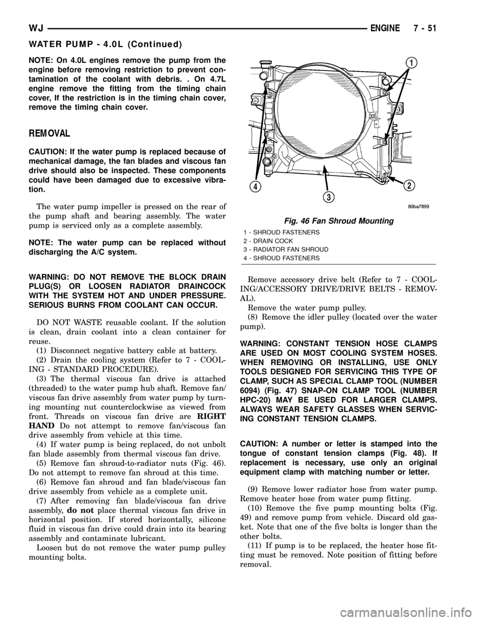
(5) Remove fan shroud-to-radiator nuts (Fig. 46).
Do not attempt to remove fan shroud at this time.
(6) Remove fan shroud and fan blade/viscous fan
drive assembly from vehicle as a complete unit.
(7) After removing fan blade/viscous fan drive
assembly,do notplace thermal viscous fan drive in
horizontal position. If stored horizontally, silicone
fluid in viscous fan drive could drain into its bearing
assembly and contaminate lubricant.
Loosen but do not remove the water pump pulley
mounting bolts.Remove accessory drive belt (Refer to 7 - COOL-
ING/ACCESSORY DRIVE/DRIVE BELTS - REMOV-
AL).
Remove the water pump pulley.
(8) Remove the idler pulley (located over the water
pump).
WARNING: CONSTANT TENSION HOSE CLAMPS
ARE USED ON MOST COOLING SYSTEM HOSES.
WHEN REMOVING OR INSTALLING, USE ONLY
TOOLS DESIGNED FOR SERVICING THIS TYPE OF
CLAMP, SUCH AS SPECIAL CLAMP TOOL (NUMBER
6094) (Fig. 47) SNAP-ON CLAMP TOOL (NUMBER
HPC-20) MAY BE USED FOR LARGER CLAMPS.
ALWAYS WEAR SAFETY GLASSES WHEN SERVIC-
ING CONSTANT TENSION CLAMPS.
CAUTION: A number or letter is stamped into the
tongue of constant tension clamps (Fig. 48). If
replacement is necessary, use only an original
equipment clamp with matching number or letter.
(9) Remove lower radiator hose from water pump.
Remove heater hose from water pump fitting.
(10) Remove the five pump mounting bolts (Fig.
49) and remove pump from vehicle. Discard old gas-
ket. Note that one of the five bolts is longer than the
other bolts.
(11) If pump is to be replaced, the heater hose fit-
ting must be removed. Note position of fitting before
removal.
Fig. 46 Fan Shroud Mounting
1 - SHROUD FASTENERS
2 - DRAIN COCK
3 - RADIATOR FAN SHROUD
4 - SHROUD FASTENERS
WJENGINE 7 - 51
WATER PUMP - 4.0L (Continued)
Page 551 of 2199
INSTALLATION
The following service procedure applies to vehicles
manufactured for sale in North America, which have
removable child seat tether anchor brackets that are
located on the inner liftgate opening header. Vehicles
manufactured for sale in Rest-Of-World (ROW) mar-
kets have child tether anchors that are integral to,
and are only serviced with the rear seat back panels.
(1) Position the child tether anchor bracket onto
the inner liftgate opening header (Fig. 12).
(2) Install and tighten the screw that secures the
child tether anchor bracket to the inner liftgate open-
ing header. Tighten the screw to 11.8 N´m (105 in.
lbs.).
(3) Reinstall the cover into the child tether anchor
bezel in the headliner near the liftgate opening
header.
CLOCKSPRING
DESCRIPTION
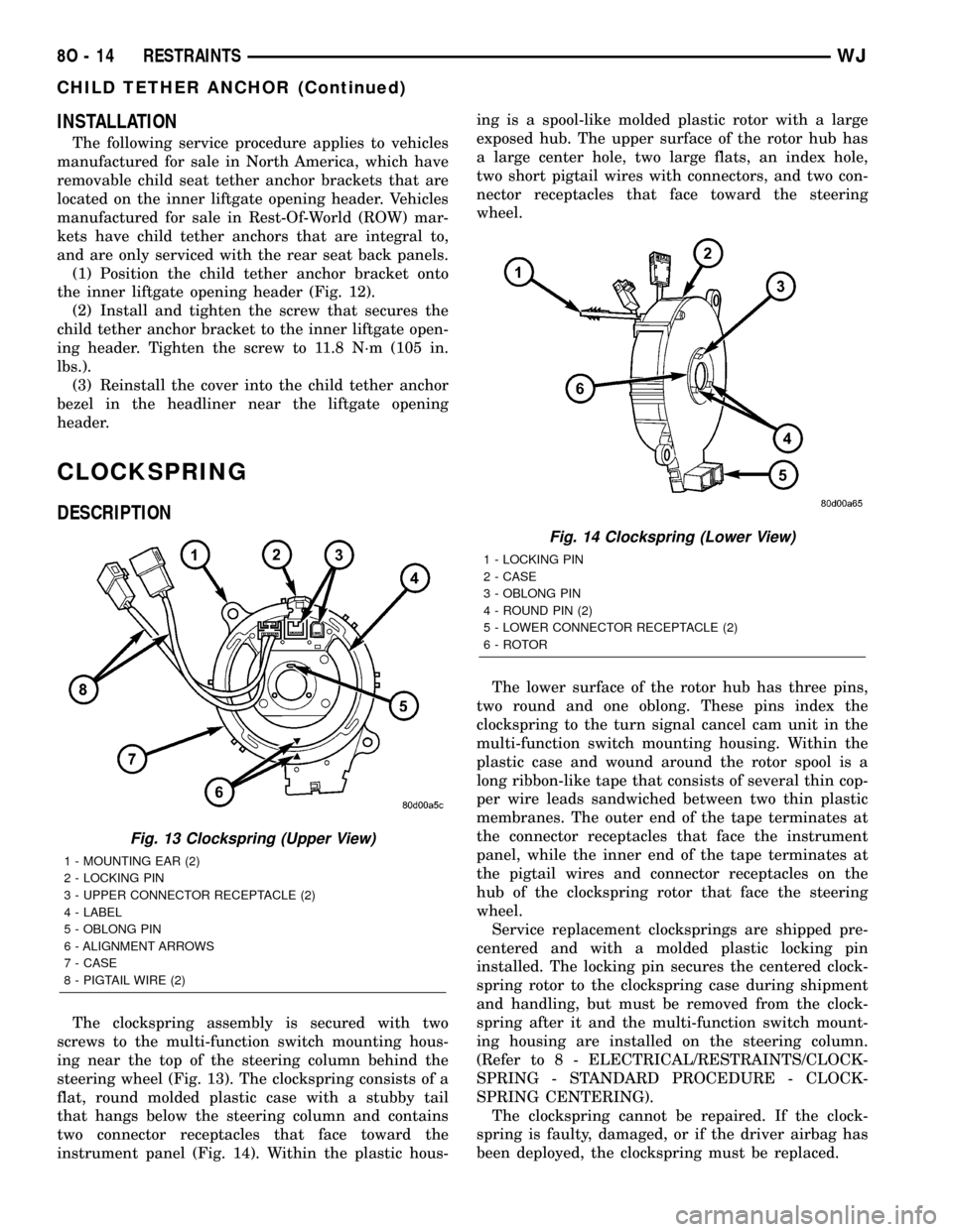
The clockspring assembly is secured with two
screws to the multi-function switch mounting hous-
ing near the top of the steering column behind the
steering wheel (Fig. 13). The clockspring consists of a
flat, round molded plastic case with a stubby tail
that hangs below the steering column and contains
two connector receptacles that face toward the
instrument panel (Fig. 14). Within the plastic hous-ing is a spool-like molded plastic rotor with a large
exposed hub. The upper surface of the rotor hub has
a large center hole, two large flats, an index hole,
two short pigtail wires with connectors, and two con-
nector receptacles that face toward the steering
wheel.
The lower surface of the rotor hub has three pins,
two round and one oblong. These pins index the
clockspring to the turn signal cancel cam unit in the
multi-function switch mounting housing. Within the
plastic case and wound around the rotor spool is a
long ribbon-like tape that consists of several thin cop-
per wire leads sandwiched between two thin plastic
membranes. The outer end of the tape terminates at
the connector receptacles that face the instrument
panel, while the inner end of the tape terminates at
the pigtail wires and connector receptacles on the
hub of the clockspring rotor that face the steering
wheel.
Service replacement clocksprings are shipped pre-
centered and with a molded plastic locking pin
installed. The locking pin secures the centered clock-
spring rotor to the clockspring case during shipment
and handling, but must be removed from the clock-
spring after it and the multi-function switch mount-
ing housing are installed on the steering column.
(Refer to 8 - ELECTRICAL/RESTRAINTS/CLOCK-
SPRING - STANDARD PROCEDURE - CLOCK-
SPRING CENTERING).
The clockspring cannot be repaired. If the clock-
spring is faulty, damaged, or if the driver airbag has
been deployed, the clockspring must be replaced.
Fig. 13 Clockspring (Upper View)
1 - MOUNTING EAR (2)
2 - LOCKING PIN
3 - UPPER CONNECTOR RECEPTACLE (2)
4 - LABEL
5 - OBLONG PIN
6 - ALIGNMENT ARROWS
7 - CASE
8 - PIGTAIL WIRE (2)
Fig. 14 Clockspring (Lower View)
1 - LOCKING PIN
2 - CASE
3 - OBLONG PIN
4 - ROUND PIN (2)
5 - LOWER CONNECTOR RECEPTACLE (2)
6 - ROTOR
8O - 14 RESTRAINTSWJ
CHILD TETHER ANCHOR (Continued)
Page 1310 of 2199
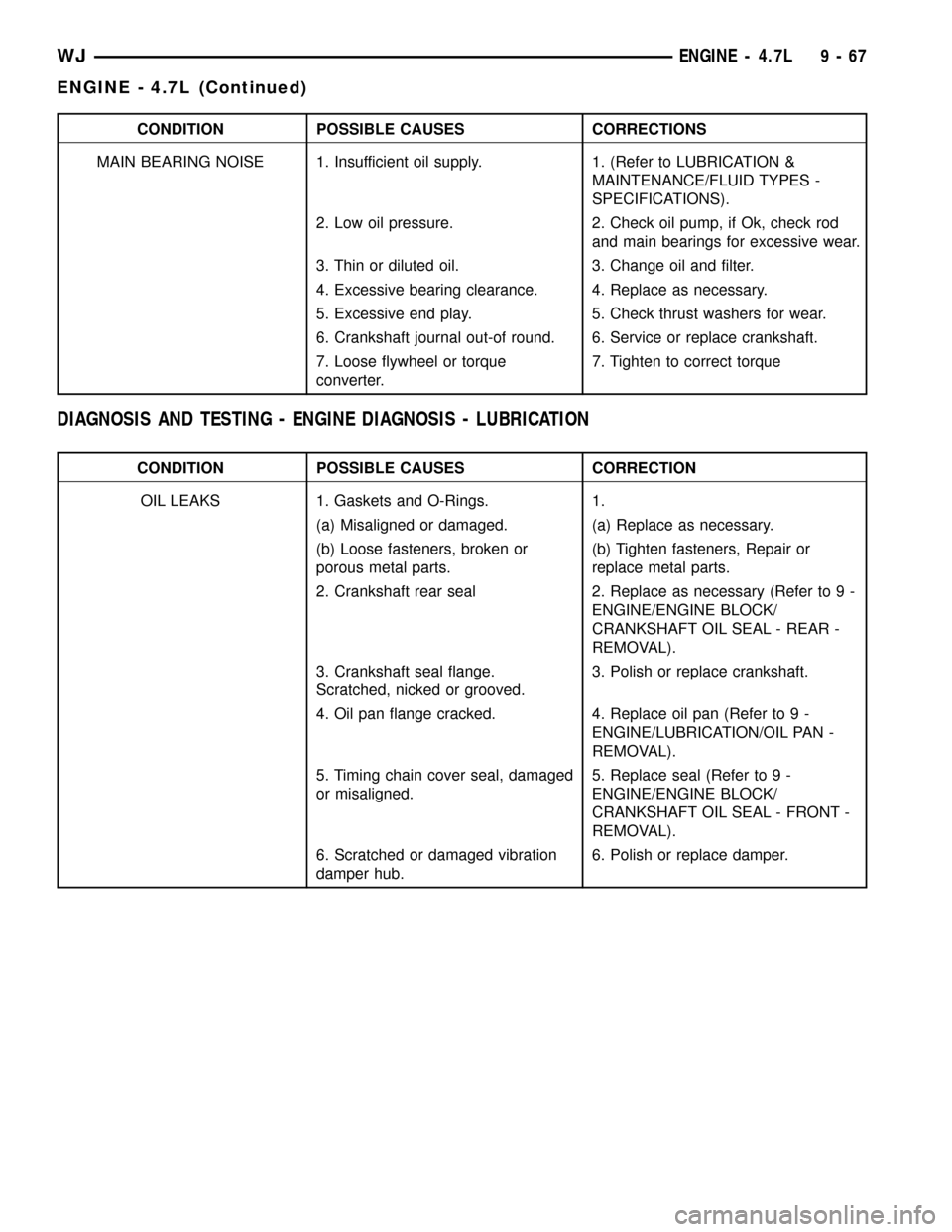
CONDITION POSSIBLE CAUSES CORRECTIONS
MAIN BEARING NOISE 1. Insufficient oil supply. 1. (Refer to LUBRICATION &
MAINTENANCE/FLUID TYPES -
SPECIFICATIONS).
2. Low oil pressure. 2. Check oil pump, if Ok, check rod
and main bearings for excessive wear.
3. Thin or diluted oil. 3. Change oil and filter.
4. Excessive bearing clearance. 4. Replace as necessary.
5. Excessive end play. 5. Check thrust washers for wear.
6. Crankshaft journal out-of round. 6. Service or replace crankshaft.
7. Loose flywheel or torque
converter.7. Tighten to correct torque
DIAGNOSIS AND TESTING - ENGINE DIAGNOSIS - LUBRICATION
CONDITION POSSIBLE CAUSES CORRECTION
OIL LEAKS 1. Gaskets and O-Rings. 1.
(a) Misaligned or damaged. (a) Replace as necessary.
(b) Loose fasteners, broken or
porous metal parts.(b) Tighten fasteners, Repair or
replace metal parts.
2. Crankshaft rear seal 2. Replace as necessary (Refer to 9 -
ENGINE/ENGINE BLOCK/
CRANKSHAFT OIL SEAL - REAR -
REMOVAL).
3. Crankshaft seal flange.
Scratched, nicked or grooved.3. Polish or replace crankshaft.
4. Oil pan flange cracked. 4. Replace oil pan (Refer to 9 -
ENGINE/LUBRICATION/OIL PAN -
REMOVAL).
5. Timing chain cover seal, damaged
or misaligned.5. Replace seal (Refer to 9 -
ENGINE/ENGINE BLOCK/
CRANKSHAFT OIL SEAL - FRONT -
REMOVAL).
6. Scratched or damaged vibration
damper hub.6. Polish or replace damper.
WJENGINE - 4.7L 9 - 67
ENGINE - 4.7L (Continued)