JEEP GRAND CHEROKEE 2003 WJ / 2.G Workshop Manual
Manufacturer: JEEP, Model Year: 2003, Model line: GRAND CHEROKEE, Model: JEEP GRAND CHEROKEE 2003 WJ / 2.GPages: 2199, PDF Size: 76.01 MB
Page 1851 of 2199
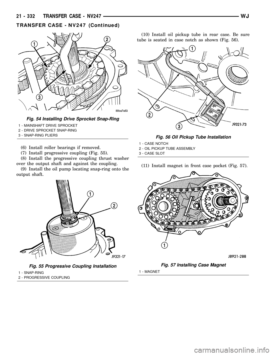
(6) Install roller bearings if removed.
(7) Install progressive coupling (Fig. 55).
(8) Install the progressive coupling thrust washer
over the output shaft and against the coupling.
(9) Install the oil pump locating snap-ring onto the
output shaft.(10) Install oil pickup tube in rear case. Be sure
tube is seated in case notch as shown (Fig. 56).
(11) Install magnet in front case pocket (Fig. 57).
Fig. 54 Installing Drive Sprocket Snap-Ring
1 - MAINSHAFT DRIVE SPROCKET
2 - DRIVE SPROCKET SNAP-RING
3 - SNAP-RING PLIERS
Fig. 55 Progressive Coupling Installation
1 - SNAP-RING
2 - PROGRESSIVE COUPLING
Fig. 56 Oil Pickup Tube Installation
1 - CASE NOTCH
2 - OIL PICKUP TUBE ASSEMBLY
3 - CASE SLOT
Fig. 57 Installing Case Magnet
1 - MAGNET
21 - 332 TRANSFER CASE - NV247WJ
TRANSFER CASE - NV247 (Continued)
Page 1852 of 2199
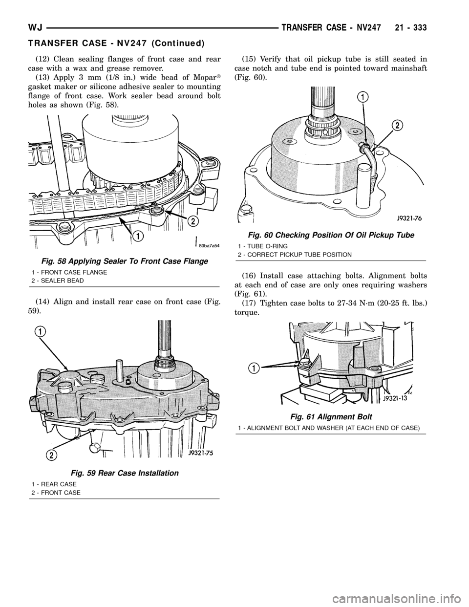
(12) Clean sealing flanges of front case and rear
case with a wax and grease remover.
(13) Apply 3 mm (1/8 in.) wide bead of Mopart
gasket maker or silicone adhesive sealer to mounting
flange of front case. Work sealer bead around bolt
holes as shown (Fig. 58).
(14) Align and install rear case on front case (Fig.
59).(15) Verify that oil pickup tube is still seated in
case notch and tube end is pointed toward mainshaft
(Fig. 60).
(16) Install case attaching bolts. Alignment bolts
at each end of case are only ones requiring washers
(Fig. 61).
(17) Tighten case bolts to 27-34 N´m (20-25 ft. lbs.)
torque.
Fig. 58 Applying Sealer To Front Case Flange
1 - FRONT CASE FLANGE
2 - SEALER BEAD
Fig. 59 Rear Case Installation
1 - REAR CASE
2 - FRONT CASE
Fig. 60 Checking Position Of Oil Pickup Tube
1 - TUBE O-RING
2 - CORRECT PICKUP TUBE POSITION
Fig. 61 Alignment Bolt
1 - ALIGNMENT BOLT AND WASHER (AT EACH END OF CASE)
WJTRANSFER CASE - NV247 21 - 333
TRANSFER CASE - NV247 (Continued)
Page 1853 of 2199
COMPANION FLANGE AND RANGE LEVER
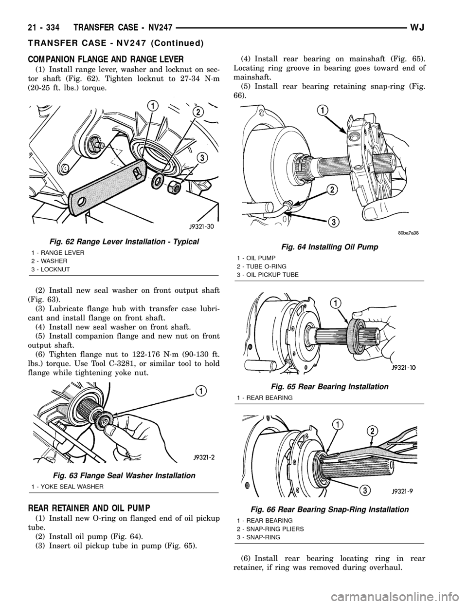
(1) Install range lever, washer and locknut on sec-
tor shaft (Fig. 62). Tighten locknut to 27-34 N´m
(20-25 ft. lbs.) torque.
(2) Install new seal washer on front output shaft
(Fig. 63).
(3) Lubricate flange hub with transfer case lubri-
cant and install flange on front shaft.
(4) Install new seal washer on front shaft.
(5) Install companion flange and new nut on front
output shaft.
(6) Tighten flange nut to 122-176 N´m (90-130 ft.
lbs.) torque. Use Tool C-3281, or similar tool to hold
flange while tightening yoke nut.
REAR RETAINER AND OIL PUMP
(1) Install new O-ring on flanged end of oil pickup
tube.
(2) Install oil pump (Fig. 64).
(3) Insert oil pickup tube in pump (Fig. 65).(4) Install rear bearing on mainshaft (Fig. 65).
Locating ring groove in bearing goes toward end of
mainshaft.
(5) Install rear bearing retaining snap-ring (Fig.
66).
(6) Install rear bearing locating ring in rear
retainer, if ring was removed during overhaul.
Fig. 62 Range Lever Installation - Typical
1 - RANGE LEVER
2 - WASHER
3 - LOCKNUT
Fig. 63 Flange Seal Washer Installation
1 - YOKE SEAL WASHER
Fig. 64 Installing Oil Pump
1 - OIL PUMP
2 - TUBE O-RING
3 - OIL PICKUP TUBE
Fig. 65 Rear Bearing Installation
1 - REAR BEARING
Fig. 66 Rear Bearing Snap-Ring Installation
1 - REAR BEARING
2 - SNAP-RING PLIERS
3 - SNAP-RING
21 - 334 TRANSFER CASE - NV247WJ
TRANSFER CASE - NV247 (Continued)
Page 1854 of 2199
(7) Apply 3 mm (1/8 in.) wide bead of Mopartgas-
ket maker or silicone adhesive sealer to mounting
surface of rear retainer. Allow sealer to set-up
slightly before proceeding.
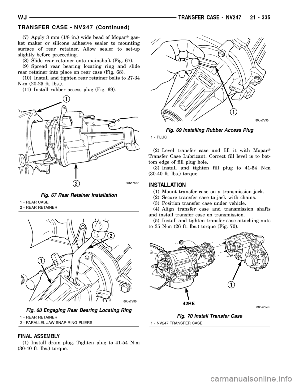
(8) Slide rear retainer onto mainshaft (Fig. 67).
(9) Spread rear bearing locating ring and slide
rear retainer into place on rear case (Fig. 68).
(10) Install and tighten rear retainer bolts to 27-34
N´m (20-25 ft. lbs.).
(11) Install rubber access plug (Fig. 69).
FINAL ASSEMBLY
(1) Install drain plug. Tighten plug to 41-54 N´m
(30-40 ft. lbs.) torque.(2) Level transfer case and fill it with Mopart
Transfer Case Lubricant. Correct fill level is to bot-
tom edge of fill plug hole.
(3) Install and tighten fill plug to 41-54 N´m
(30-40 ft. lbs.) torque.
INSTALLATION
(1) Mount transfer case on a transmission jack.
(2) Secure transfer case to jack with chains.
(3) Position transfer case under vehicle.
(4) Align transfer case and transmission shafts
and install transfer case on transmission.
(5) Install and tighten transfer case attaching nuts
to 35 N´m (26 ft. lbs.) torque (Fig. 70).Fig. 67 Rear Retainer Installation
1 - REAR CASE
2 - REAR RETAINER
Fig. 68 Engaging Rear Bearing Locating Ring
1 - REAR RETAINER
2 - PARALLEL JAW SNAP-RING PLIERS
Fig. 69 Installing Rubber Access Plug
1 - PLUG
Fig. 70 Install Transfer Case
1 - NV247 TRANSFER CASE
WJTRANSFER CASE - NV247 21 - 335
TRANSFER CASE - NV247 (Continued)
Page 1855 of 2199
(6) Connect front propeller shaft and install rear
propeller shaft. (Refer to 3 - DIFFERENTIAL &
DRIVELINE/PROPELLER SHAFT/PROPELLER
SHAFT - INSTALLATION)
(7) Fill transfer case with correct fluid. Check
transmission fluid level. Correct as necessary.
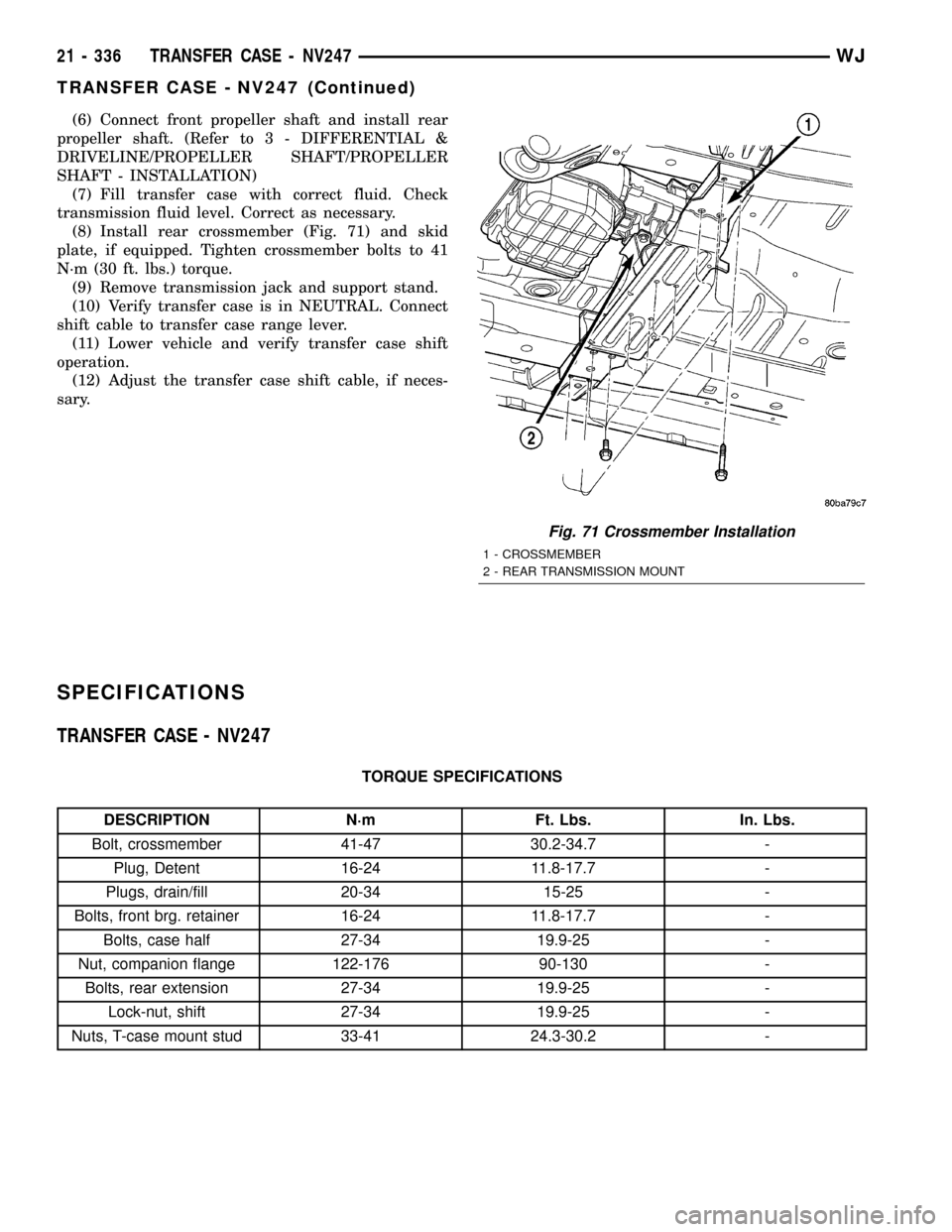
(8) Install rear crossmember (Fig. 71) and skid
plate, if equipped. Tighten crossmember bolts to 41
N´m (30 ft. lbs.) torque.
(9) Remove transmission jack and support stand.
(10) Verify transfer case is in NEUTRAL. Connect
shift cable to transfer case range lever.
(11) Lower vehicle and verify transfer case shift
operation.
(12) Adjust the transfer case shift cable, if neces-
sary.
SPECIFICATIONS
TRANSFER CASE - NV247
TORQUE SPECIFICATIONS
DESCRIPTION N´m Ft. Lbs. In. Lbs.
Bolt, crossmember 41-47 30.2-34.7 -
Plug, Detent 16-24 11.8-17.7 -
Plugs, drain/fill 20-34 15-25 -
Bolts, front brg. retainer 16-24 11.8-17.7 -
Bolts, case half 27-34 19.9-25 -
Nut, companion flange 122-176 90-130 -
Bolts, rear extension 27-34 19.9-25 -
Lock-nut, shift 27-34 19.9-25 -
Nuts, T-case mount stud 33-41 24.3-30.2 -
Fig. 71 Crossmember Installation
1 - CROSSMEMBER
2 - REAR TRANSMISSION MOUNT
21 - 336 TRANSFER CASE - NV247WJ
TRANSFER CASE - NV247 (Continued)
Page 1856 of 2199

SPECIAL TOOLS
TRANSFER CASE - NV247
Installer, Bearing - 5066
Installer, Seal - 6952-A
Installer, Bearing - 6953
Remover, Bushing - 6957
Installer, Seal - C-3995-A
Handle - C-4171
Installer, Bushing - 8145
Remover, Bearing - C-4210
Remover, Bearing - L-4454
Cup - 8148
WJTRANSFER CASE - NV247 21 - 337
TRANSFER CASE - NV247 (Continued)
Page 1857 of 2199

FLUID
STANDARD PROCEDURE - FLUID DRAIN/
REFILL
The fill and drain plugs are both in the rear case
(Fig. 72).
(1) Raise vehicle.
(2) Position drain pan under transfer case.
(3) Remove drain and fill plugs and drain lubri-
cant completely.
(4) Install drain plug. Tighten plug to 20-34 N´m
(15-25 ft. lbs.).
(5) Remove drain pan.(6) Fill transfer case to bottom edge of fill plug
opening with MopartTransfer Case Lubricant.
(7) Install and tighten fill plug to 20-34 N´m
(15-25 ft. lbs.).
(8) Lower vehicle.
FRONT OUTPUT SHAFT SEAL
REMOVAL
(1) Raise vehicle on hoist.
(2) Remove front propeller shaft. (Refer to 3 - DIF-
FERENTIAL & DRIVELINE/PROPELLER SHAFT/
PROPELLER SHAFT - REMOVAL)
(3) Remove front output shaft companion shaft.
(4) Remove seal from front case with pry tool (Fig.
73).
INSTALLATION
(1) Install new front output seal in front case with
Installer Tool 6952-A as follows:
(a) Place new seal on tool. Garter spring on seal
goes toward interior of case.
(b) Start seal in bore with light taps from ham-
mer (Fig. 74). Once seal is started, continue tap-
ping seal into bore until installer tool seats against
case.
(2) Install companion flange and torque nut to
122-176 N´m (90-130 ft. lbs.).
(3) Install front propeller shaft. (Refer to 3 - DIF-
FERENTIAL & DRIVELINE/PROPELLER SHAFT/
PROPELLER SHAFT - INSTALLATION)
Installer, Bearign - 8128
Installer, Seal - 7884
Fig. 72 Fill/Drain Plug and I.D. Tag Location -
Typical
1 - I.D. TAG
2 - FILL PLUG
3 - DRAIN PLUG
Fig. 73 Remove Front Output Shaft Seal
1 - OUTPUT SHAFT SEAL
2 - PRYBAR
21 - 338 TRANSFER CASE - NV247WJ
TRANSFER CASE - NV247 (Continued)
Page 1858 of 2199
REAR RETAINER BUSHING
AND SEAL
REMOVAL
(1) Raise vehicle on hoist.
(2) Remove rear propeller shaft. (Refer to 3 - DIF-
FERENTIAL & DRIVELINE/PROPELLER SHAFT/
PROPELLER SHAFT - REMOVAL)
(3) Using a suitable pry tool or slide-hammer
mounted screw, remove the rear retainer seal.
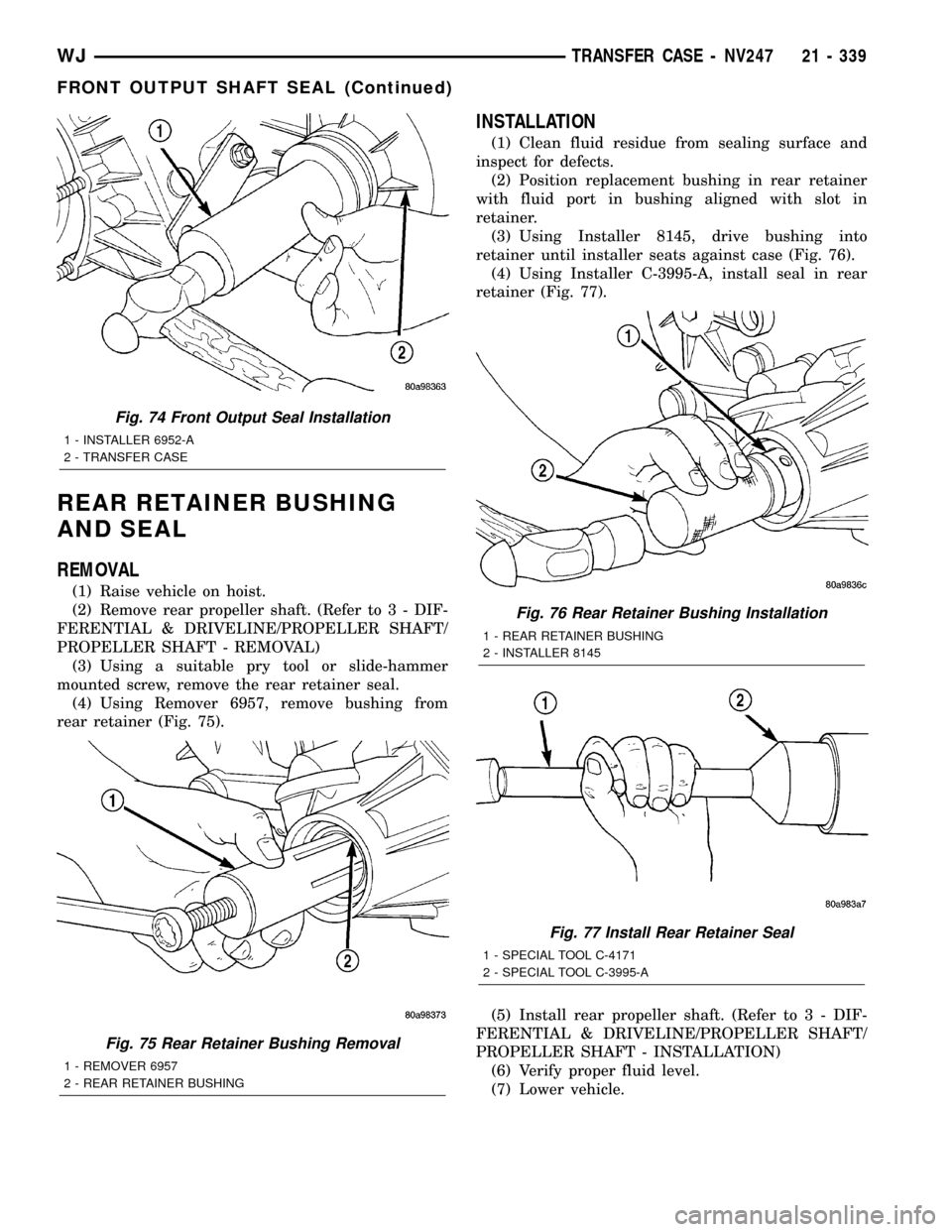
(4) Using Remover 6957, remove bushing from
rear retainer (Fig. 75).
INSTALLATION
(1) Clean fluid residue from sealing surface and
inspect for defects.
(2) Position replacement bushing in rear retainer
with fluid port in bushing aligned with slot in
retainer.
(3) Using Installer 8145, drive bushing into
retainer until installer seats against case (Fig. 76).
(4) Using Installer C-3995-A, install seal in rear
retainer (Fig. 77).
(5) Install rear propeller shaft. (Refer to 3 - DIF-
FERENTIAL & DRIVELINE/PROPELLER SHAFT/
PROPELLER SHAFT - INSTALLATION)
(6) Verify proper fluid level.
(7) Lower vehicle.
Fig. 74 Front Output Seal Installation
1 - INSTALLER 6952-A
2 - TRANSFER CASE
Fig. 75 Rear Retainer Bushing Removal
1 - REMOVER 6957
2 - REAR RETAINER BUSHING
Fig. 76 Rear Retainer Bushing Installation
1 - REAR RETAINER BUSHING
2 - INSTALLER 8145
Fig. 77 Install Rear Retainer Seal
1 - SPECIAL TOOL C-4171
2 - SPECIAL TOOL C-3995-A
WJTRANSFER CASE - NV247 21 - 339
FRONT OUTPUT SHAFT SEAL (Continued)
Page 1859 of 2199
SHIFT CABLE
REMOVAL
(1) Shift transfer case into NEUTRAL.
(2) Raise vehicle.
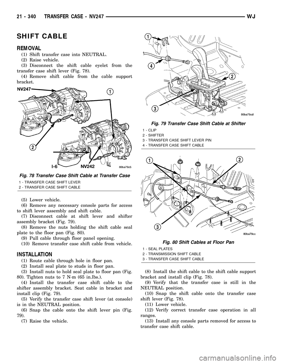
(3) Disconnect the shift cable eyelet from the
transfer case shift lever (Fig. 78).
(4) Remove shift cable from the cable support
bracket.
(5) Lower vehicle.
(6) Remove any necessary console parts for access
to shift lever assembly and shift cable.
(7) Disconnect cable at shift lever and shifter
assembly bracket (Fig. 79).
(8) Remove the nuts holding the shift cable seal
plate to the floor pan (Fig. 80).
(9) Pull cable through floor panel opening.
(10) Remove transfer case shift cable from vehicle.
INSTALLATION
(1) Route cable through hole in floor pan.
(2) Install seal plate to studs in floor pan.
(3) Install nuts to hold seal plate to floor pan (Fig.
80). Tighten nuts to 7 N´m (65 in.lbs.).
(4) Install the transfer case shift cable to the
shifter assembly bracket. Seat cable in bracket and
install clip (Fig. 79).
(5) Verify the transfer case shift lever (at console)
is in the NEUTRAL position.
(6) Snap the cable onto the shift lever pin (Fig.
79).
(7) Raise the vehicle.(8) Install the shift cable to the shift cable support
bracket and install clip (Fig. 78).
(9) Verify that the transfer case is still in the
NEUTRAL position.
(10) Snap the shift cable onto the transfer case
shift lever (Fig. 78).
(11) Lower vehicle.
(12) Verify correct transfer case operation in all
ranges.
(13) Install any console parts removed for access to
transfer case shift cable.
Fig. 78 Transfer Case Shift Cable at Transfer Case
1 - TRANSFER CASE SHIFT LEVER
2 - TRANSFER CASE SHIFT CABLE
Fig. 79 Transfer Case Shift Cable at Shifter
1 - CLIP
2 - SHIFTER
3 - TRANSFER CASE SHIFT LEVER PIN
4 - TRANSFER CASE SHIFT CABLE
Fig. 80 Shift Cables at Floor Pan
1 - SEAL PLATES
2 - TRANSMISSION SHIFT CABLE
3 - TRANSFER CASE SHIFT CABLE
21 - 340 TRANSFER CASE - NV247WJ
Page 1860 of 2199
TIRES/WHEELS
TABLE OF CONTENTS
page page
TIRES/WHEELS
DIAGNOSIS AND TESTING - TIRE AND
WHEEL RUNOUT......................1
STANDARD PROCEDURE
STANDARD PROCEDURE - TIRE AND
WHEEL BALANCE......................2
STANDARD PROCEDURE - MATCH
MOUNTING...........................4
STANDARD PROCEDURE - TIRE ROTATION . 5
STANDARD PROCEDURE - WHEEL
INSTALLATION........................5
TIRES
DESCRIPTION
DESCRIPTION - TIRES..................6
DESCRIPTION - RADIAL±PLY TIRES.......6
DESCRIPTION - TIRE INFLATION
PRESSURES..........................6
DESCRIPTION - TIRE PRESSURE FOR
HIGH SPEED..........................7
DESCRIPTION - REPLACEMENT TIRES.....7
DIAGNOSIS AND TESTING
DIAGNOSIS AND TESTING - PRESSURE
GAUGES.............................8
DIAGNOSIS AND TESTING - TREAD WEAR
INDICATORS..........................8
DIAGNOSIS AND TESTING - TIRE WEAR
PATTERNS...........................8
DIAGNOSIS AND TESTING - TIRE NOISE
OR VIBRATION........................8STANDARD PROCEDURE - REPAIRING
LEAKS...............................8
CLEANING.............................9
SPECIFICATIONS
TIRES...............................9
SPECIFICATIONS -.....................9
SPARE TIRE
DESCRIPTION - SPARE / TEMPORARY TIRE . . 10
WHEELS
DESCRIPTION.........................10
DIAGNOSIS AND TESTING - WHEEL
INSPECTION.........................10
STANDARD PROCEDURE - WHEEL
REPLACEMENT.......................10
SPECIFICATIONS
TORQUE CHART......................11
STUDS
REMOVAL.............................11
INSTALLATION.........................11
TIRE PRESSURE MONITORING
DESCRIPTION.........................12
OPERATION...........................12
DIAGNOSIS AND TESTING - TIRE PRESSURE
MONITORING SYSTEM.................12
SENSOR
REMOVAL - TIRE PRESSURE SENSOR/
TRANSMITTER.......................12
INSTALLATION - TIRE PRESSURE SENSOR/
TRANSMITTER.......................13
TIRES/WHEELS
DIAGNOSIS AND TESTING - TIRE AND WHEEL
RUNOUT
Radial runout is the difference between the high
and low points on the tire or wheel (Fig. 1).
Lateral runout is thewobbleof the tire or wheel.
Radial runout of more than 1.5 mm (.060 inch)
measured at the center line of the tread may cause
the vehicle to shake.
Lateral runout of more than 2.0 mm (.080 inch)
measured near the shoulder of the tire may cause the
vehicle to shake.
Sometimes radial runout can be reduced. Relocate
the wheel and tire assembly on the mounting studs
(See Method 1). If this does not reduce runout to an
acceptable level, the tire can be rotated on the wheel.
(See Method 2).
METHOD 1 (RELOCATE WHEEL ON HUB)
(1) Drive vehicle a short distance to eliminate tire
flat spotting from a parked position.
(2) Check wheel bearings and adjust if adjustable
or replace if necessary.
(3) Check the wheel mounting surface.
(4) Relocate wheel on the mounting, two studs
over from the original position.
(5) Tighten wheel nuts until all are properly
torqued, to eliminate brake distortion.
(6) Check radial runout. If still excessive, mark
tire sidewall, wheel, and stud at point of maximum
runout and proceed to Method 2.
METHOD 2 (RELOCATE TIRE ON WHEEL)
NOTE: Rotating the tire on wheel is particularly
effective when there is runout in both tire and
wheel.
WJTIRES/WHEELS 22 - 1