head gasket JEEP GRAND CHEROKEE 2003 WJ / 2.G User Guide
[x] Cancel search | Manufacturer: JEEP, Model Year: 2003, Model line: GRAND CHEROKEE, Model: JEEP GRAND CHEROKEE 2003 WJ / 2.GPages: 2199, PDF Size: 76.01 MB
Page 1253 of 2199
FORM-IN-PLACE GASKET AND SEALER
APPLICATION
Assembling parts using a form-in-place gasket
requires care but it's easier then using precut gaskets.
MopartGasket Maker material should be applied
sparingly 1 mm (0.040 in.) diameter or less of sealant
to one gasket surface. Be certain the material sur-
rounds each mounting hole. Excess material can eas-
ily be wiped off. Components should be torqued in
place within 15 minutes. The use of a locating dowel
is recommended during assembly to prevent smear-
ing material off the location.
MopartEngine RTV GEN II or ATF RTV gasket
material should be applied in a continuous bead
approximately 3 mm (0.120 in.) in diameter. All
mounting holes must be circled. For corner sealing, a
3.17 or 6.35 mm (1/8 or 1/4 in.) drop is placed in the
center of the gasket contact area. Uncured sealant
may be removed with a shop towel. Components
should be torqued in place while the sealant is still
wet to the touch (within 10 minutes). The usage of a
locating dowel is recommended during assembly to
prevent smearing material off the location.
MopartGasket Sealant in an aerosol can should be
applied using a thin, even coat sprayed completely
over both surfaces to be joined, and both sides of a
gasket. Then proceed with assembly. Material in a
can w/applicator can be brushed on evenly over the
sealing surfaces. Material in an aerosol can should be
used on engines with multi-layer steel gaskets.
STANDARD PROCEDURE - REPAIR DAMAGED
OR WORN THREADS
CAUTION: Be sure that the tapped holes maintain
the original center line.
Damaged or worn threads can be repaired. Essen-
tially, this repair consists of:
²Drilling out worn or damaged threads.
²Tapping the hole with a special Heli-Coil Tap, or
equivalent.
²Installing an insert into the tapped hole to bring
the hole back to its original thread size.
STANDARD PROCEDUREÐHYDROSTATIC LOCK
CAUTION: DO NOT use the starter motor to rotate
the crankshaft. Severe damage could occur.
When an engine is suspected of hydrostatic lock
(regardless of what caused the problem), follow the
steps below.
(1) Perform the Fuel Pressure Release Procedure
(Refer to 14 - FUEL SYSTEM/FUEL DELIVERY -
STANDARD PROCEDURE).(2) Disconnect the negative cable(s) from the bat-
tery.
(3) Inspect air cleaner, induction system, and
intake manifold to ensure system is dry and clear of
foreign material.
(4) Place a shop towel around the spark plugs to
catch any fluid that may possibly be under pressure
in the cylinder head. Remove the spark plugs.
(5) With all spark plugs removed, rotate the crank-
shaft using a breaker bar and socket.
(6) Identify the fluid in the cylinders (coolant, fuel,
oil, etc.).
(7) Be sure all fluid has been removed from the
cylinders.
(8) Repair engine or components as necessary to
prevent this problem from occurring again.
(9) Squirt a small amount of engine oil into the
cylinders to lubricate the walls. This will prevent
damage on restart.
(10) Install new spark plugs. Tighten the spark
plugs to 41 N´m (30 ft. lbs.) torque.
(11) Drain engine oil. Remove and discard the oil
filter.
(12) Install the drain plug. Tighten the plug to 34
N´m (25 ft. lbs.) torque.
(13) Install a new oil filter.
(14) Fill engine crankcase with the specified
amount and grade of oil. (Refer to LUBRICATION &
MAINTENANCE - SPECIFICATIONS).
(15) Connect the negative cable(s) to the battery.
(16) Start the engine and check for any leaks.
STANDARD PROCEDURE - CYLINDER BORE
HONING
Before honing, stuff plenty of clean shop towels
under the bores and over the crankshaft to keep
abrasive materials from entering the crankshaft
area.
(1)
Used carefully, the Cylinder Bore Sizing Hone
C-823, equipped with 220 grit stones, is the best tool
for this job. In addition to deglazing, it will reduce
taper and out-of-round, as well as removing light scuff-
ing, scoring and scratches. Usually, a few strokes will
clean up a bore and maintain the required limits.
CAUTION: DO NOT use rigid type hones to remove
cylinder wall glaze.
(2) Deglazing of the cylinder walls may be done if
the cylinder bore is straight and round. Use a cylin-
der surfacing hone, Honing Tool C-3501, equipped
with 280 grit stones (C-3501-3810). about 20-60
strokes, depending on the bore condition, will be suf-
ficient to provide a satisfactory surface. Using honing
oil C-3501-3880, or a light honing oil, available from
major oil distributors.
9 - 10 ENGINE - 4.0LWJ
ENGINE - 4.0L (Continued)
Page 1263 of 2199
(2) Drain the coolant (Refer to 7 - COOLING -
STANDARD PROCEDURE) and disconnect the hoses
at the engine thermostat housing and the water
pump inlet. DO NOT waste reusable coolant. If the
solution is clean and is being drained only to service
the engine or cooling system, drain the coolant into a
clean container for reuse.
(3) Remove the air cleaner assembly (Refer to 9 -
ENGINE/AIR INTAKE SYSTEM/AIR CLEANER
HOUSING - REMOVAL).
(4) Remove the cylinder head cover (Refer to 9 -
ENGINE/CYLINDER HEAD/CYLINDER HEAD
COVER(S) - REMOVAL).
(5) Remove the capscrews, bridge and pivot assem-
blies and rocker arms (Refer to 9 - ENGINE/CYLIN-
DER HEAD/ROCKER ARM / ADJUSTER ASSY -
REMOVAL).
(6) Remove the push rods.Retain the push rods,
bridges, pivots and rocker arms in the same
order as removed.
(7) Remove the accessory drive belt (Refer to 7 -
COOLING/ACCESSORY DRIVE/DRIVE BELTS -
REMOVAL).
(8) Remove the A/C compressor mounting bolts
and secure the compressor to the side.
(9) Remove the power steering pump and bracket
from the intake manifold and water pump. Set the
pump and bracket aside. DO NOT disconnect the
hoses.
(10) Perform the Fuel System Pressure Release
procedure. (Refer to 14 - FUEL SYSTEM/FUEL
DELIVERY - STANDARD PROCEDURE).
(11) Disconnect the fuel supply line at the fuel rail.(12) Remove the intake and exhaust manifolds
from the engine cylinder head (Refer to 9 - ENGINE/
MANIFOLDS/INTAKE MANIFOLD - REMOVAL).
(13) Remove the coil rail (Refer to 8 - ELECTRI-
CAL/IGNITION CONTROL/COIL RAIL - REMOV-
AL).
(14) Remove spark plugs (Refer to 8 - ELECTRI-
CAL/IGNITION CONTROL/SPARK PLUG - REMOV-
AL).
(15) Disconnect the temperature sending unit wire
connector.
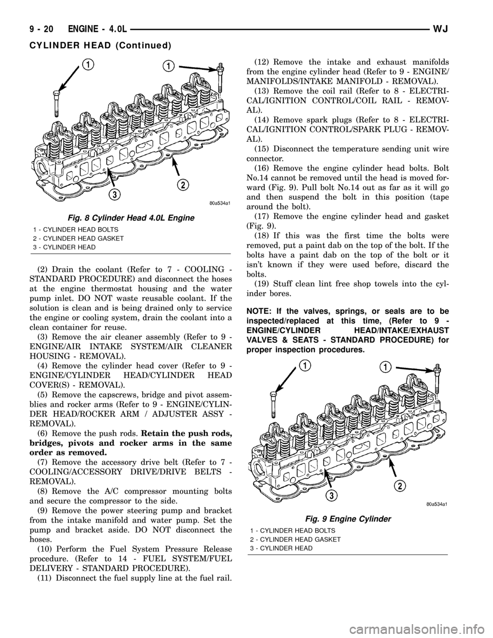
(16) Remove the engine cylinder head bolts. Bolt
No.14 cannot be removed until the head is moved for-
ward (Fig. 9). Pull bolt No.14 out as far as it will go
and then suspend the bolt in this position (tape
around the bolt).
(17) Remove the engine cylinder head and gasket
(Fig. 9).
(18) If this was the first time the bolts were
removed, put a paint dab on the top of the bolt. If the
bolts have a paint dab on the top of the bolt or it
isn't known if they were used before, discard the
bolts.
(19) Stuff clean lint free shop towels into the cyl-
inder bores.
NOTE: If the valves, springs, or seals are to be
inspected/replaced at this time, (Refer to 9 -
ENGINE/CYLINDER HEAD/INTAKE/EXHAUST
VALVES & SEATS - STANDARD PROCEDURE) for
proper inspection procedures.
Fig. 8 Cylinder Head 4.0L Engine
1 - CYLINDER HEAD BOLTS
2 - CYLINDER HEAD GASKET
3 - CYLINDER HEAD
Fig. 9 Engine Cylinder
1 - CYLINDER HEAD BOLTS
2 - CYLINDER HEAD GASKET
3 - CYLINDER HEAD
9 - 20 ENGINE - 4.0LWJ
CYLINDER HEAD (Continued)
Page 1264 of 2199
CLEANING
Thoroughly clean the engine cylinder head and cyl-
inder block mating surfaces. Clean the intake and
engine exhaust manifold and engine cylinder head
mating surfaces. Remove all gasket material and car-
bon.
Check to ensure that no coolant or foreign material
has fallen into the tappet bore area.
Remove the carbon deposits from the combustion
chambers and top of the pistons.
INSPECTION
Use a straightedge and feeler gauge to check the
flatness of the engine cylinder head and block mating
surfaces.
INSTALLATION
NOTE: This procedure can be done with the engine
in or out of the vehicle.
The engine cylinder head gasket is a composition
gasket. The gasket is to be installed DRY.DO NOT
use a gasket sealing compound on the gasket.
If the engine cylinder head is to be replaced and
the original valves used, measure the valve stem
diameter. Only standard size valves can be used with
a service replacement engine cylinder head unless
the replacement head valve stem guide bores are
reamed to accommodate oversize valve stems.
Remove all carbon buildup and reface the valves.
(1) Remove the shop towels from the cylinder
bores. Coat the bores with clean engine oil.
(2) Position the engine cylinder head gasket (with
the numbers facing up) using the alignment dowels
in the cylinder block, to position the gasket.
CAUTION: Engine cylinder head bolts should be
reused only once. Replace the head bolts if they
were used before or if they have a paint dab on the
top of the bolt.
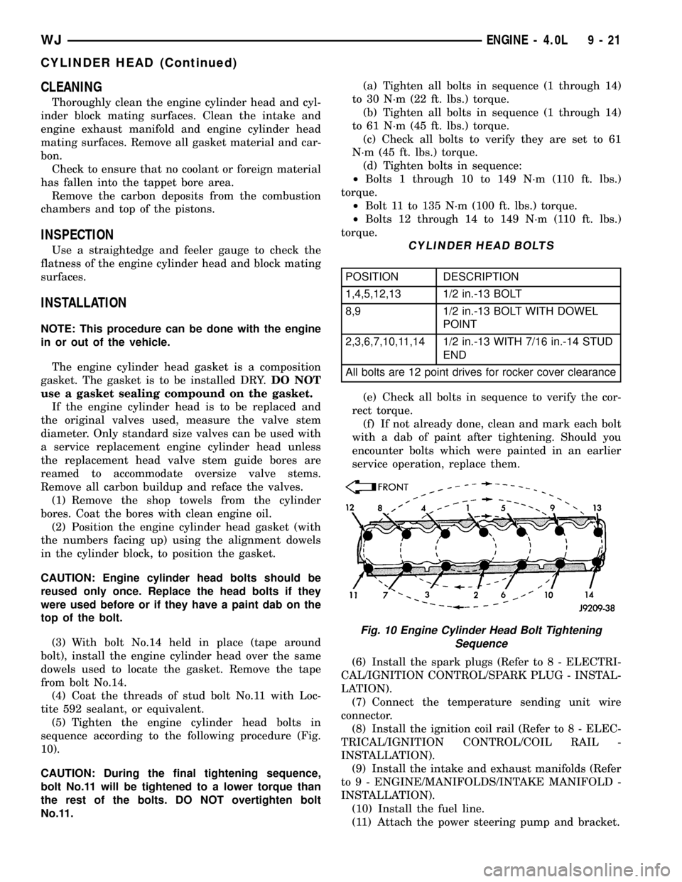
(3) With bolt No.14 held in place (tape around
bolt), install the engine cylinder head over the same
dowels used to locate the gasket. Remove the tape
from bolt No.14.
(4) Coat the threads of stud bolt No.11 with Loc-
tite 592 sealant, or equivalent.
(5) Tighten the engine cylinder head bolts in
sequence according to the following procedure (Fig.
10).
CAUTION: During the final tightening sequence,
bolt No.11 will be tightened to a lower torque than
the rest of the bolts. DO NOT overtighten bolt
No.11.(a) Tighten all bolts in sequence (1 through 14)
to 30 N´m (22 ft. lbs.) torque.
(b) Tighten all bolts in sequence (1 through 14)
to 61 N´m (45 ft. lbs.) torque.
(c) Check all bolts to verify they are set to 61
N´m (45 ft. lbs.) torque.
(d) Tighten bolts in sequence:
²Bolts 1 through 10 to 149 N´m (110 ft. lbs.)
torque.
²Bolt 11 to 135 N´m (100 ft. lbs.) torque.
²Bolts 12 through 14 to 149 N´m (110 ft. lbs.)
torque.
CYLINDER HEAD BOLTS
POSITION DESCRIPTION
1,4,5,12,13 1/2 in.-13 BOLT
8,9 1/2 in.-13 BOLT WITH DOWEL
POINT
2,3,6,7,10,11,14 1/2 in.-13 WITH 7/16 in.-14 STUD
END
All bolts are 12 point drives for rocker cover clearance
(e) Check all bolts in sequence to verify the cor-
rect torque.
(f) If not already done, clean and mark each bolt
with a dab of paint after tightening. Should you
encounter bolts which were painted in an earlier
service operation, replace them.
(6) Install the spark plugs (Refer to 8 - ELECTRI-
CAL/IGNITION CONTROL/SPARK PLUG - INSTAL-
LATION).
(7) Connect the temperature sending unit wire
connector.
(8) Install the ignition coil rail (Refer to 8 - ELEC-
TRICAL/IGNITION CONTROL/COIL RAIL -
INSTALLATION).
(9) Install the intake and exhaust manifolds (Refer
to 9 - ENGINE/MANIFOLDS/INTAKE MANIFOLD -
INSTALLATION).
(10) Install the fuel line.
(11) Attach the power steering pump and bracket.
Fig. 10 Engine Cylinder Head Bolt Tightening
Sequence
WJENGINE - 4.0L 9 - 21
CYLINDER HEAD (Continued)
Page 1265 of 2199
(12) Install the push rods, rocker arms, pivots and
bridges in the order they were removed (Refer to 9 -
ENGINE/CYLINDER HEAD/ROCKER ARM /
ADJUSTER ASSY - INSTALLATION).
(13) Install the engine cylinder head cover (Refer
to 9 - ENGINE/CYLINDER HEAD/CYLINDER
HEAD COVER(S) - INSTALLATION).
(14) Attach the air conditioner compressor mount-
ing bracket to the engine cylinder head and block.
Tighten the bolts to 40 N´m (30 ft. lbs.) torque.
(15) Attach the air conditioning compressor to the
bracket. Tighten the bolts to 27 N´m (20 ft. lbs.)
torque.
CAUTION: The serpentine drive belt must be routed
correctly. Incorrect routing can cause the water
pump to turn in the opposite direction causing the
engine to overheat.
(16) Install the serpentine drive belt. (Refer to 7 -
COOLING/ACCESSORY DRIVE/DRIVE BELTS -
INSTALLATION).
(17) Install the air cleaner and ducting.
(18) Connect the hoses to the engine thermostat
housing and fill the cooling system to the specified
level (Refer to 7 - COOLING - STANDARD PROCE-
DURE).
(19) The automatic transmission throttle linkage
and cable must be adjusted after completing the
engine cylinder head installation (Refer to 21 -
TRANSMISSION/TRANSAXLE/AUTOMATIC - AW4/
THROTTLE VALVE CABLE - ADJUSTMENTS).
(20) Install the temperature sending unit and con-
nect the wire connector.
(21) If equipped with air conditioning, install A/C
compressor (Refer to 24 - HEATING & AIR CONDI-
TIONING/PLUMBING/A/C COMPRESSOR -
INSTALLATION) and charge A/C system (Refer to 24
- HEATING & AIR CONDITIONING/PLUMBING -
STANDARD PROCEDURE).
(22) Connect negative cable to battery.
WARNING: USE EXTREME CAUTION WHEN THE
ENGINE IS OPERATING. DO NOT STAND IN DIRECT
LINE WITH THE FAN. DO NOT PUT HANDS NEAR
THE PULLEYS, BELTS OR FAN. DO NOT WEAR
LOOSE CLOTHING.
(23) Operate the engine with the radiator cap off.
Inspect for leaks and continue operating the engine
until the engine thermostat opens. Add coolant, if
required.CYLINDER HEAD COVER(S)
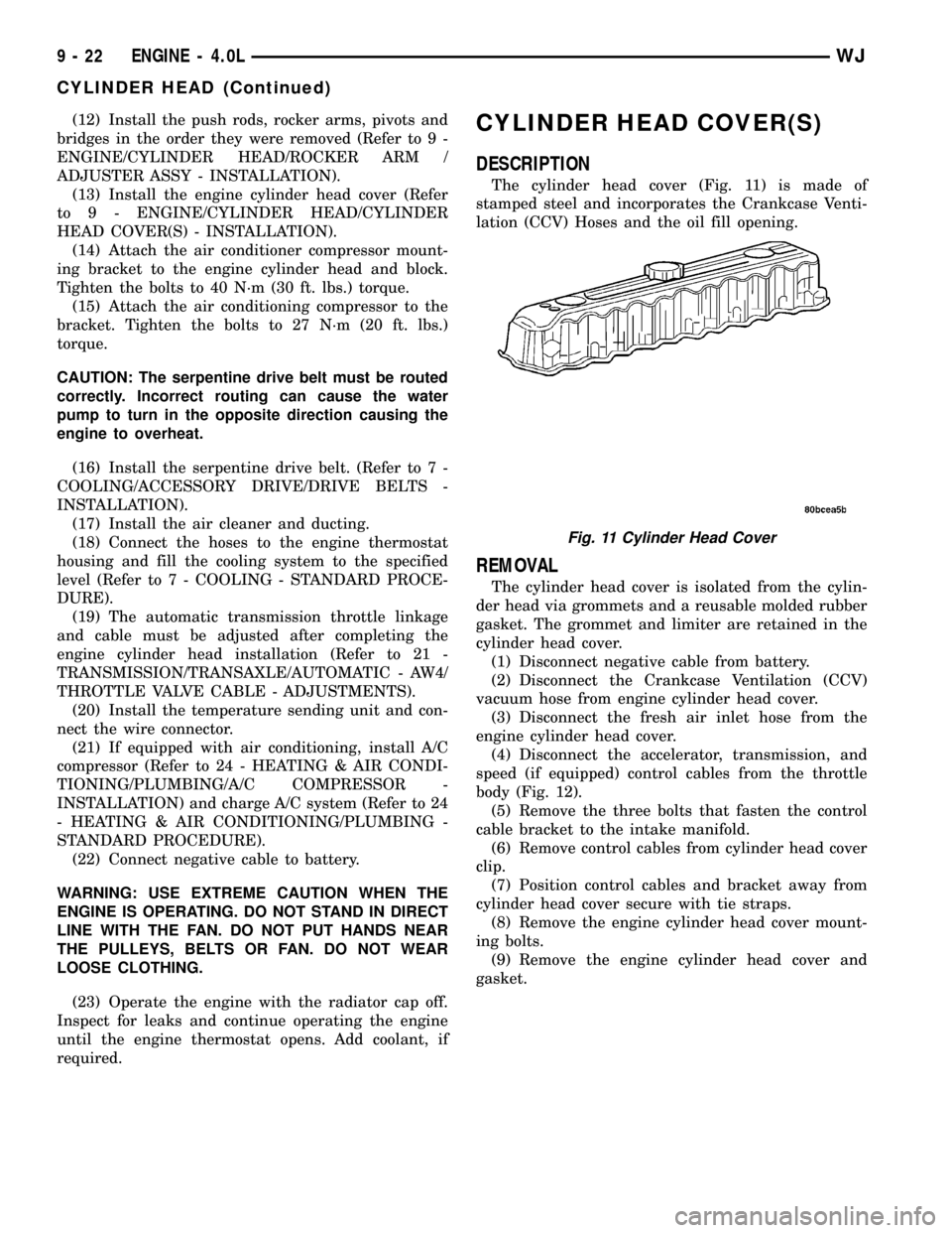
DESCRIPTION
The cylinder head cover (Fig. 11) is made of
stamped steel and incorporates the Crankcase Venti-
lation (CCV) Hoses and the oil fill opening.
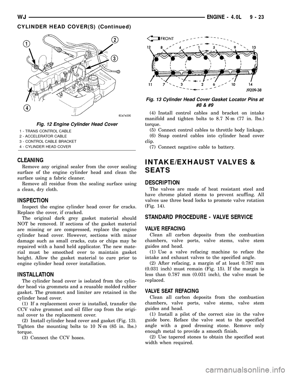
REMOVAL
The cylinder head cover is isolated from the cylin-
der head via grommets and a reusable molded rubber
gasket. The grommet and limiter are retained in the
cylinder head cover.
(1) Disconnect negative cable from battery.
(2) Disconnect the Crankcase Ventilation (CCV)
vacuum hose from engine cylinder head cover.
(3) Disconnect the fresh air inlet hose from the
engine cylinder head cover.
(4) Disconnect the accelerator, transmission, and
speed (if equipped) control cables from the throttle
body (Fig. 12).
(5) Remove the three bolts that fasten the control
cable bracket to the intake manifold.
(6) Remove control cables from cylinder head cover
clip.
(7) Position control cables and bracket away from
cylinder head cover secure with tie straps.
(8) Remove the engine cylinder head cover mount-
ing bolts.
(9) Remove the engine cylinder head cover and
gasket.
Fig. 11 Cylinder Head Cover
9 - 22 ENGINE - 4.0LWJ
CYLINDER HEAD (Continued)
Page 1266 of 2199
CLEANING
Remove any original sealer from the cover sealing
surface of the engine cylinder head and clean the
surface using a fabric cleaner.
Remove all residue from the sealing surface using
a clean, dry cloth.
INSPECTION
Inspect the engine cylinder head cover for cracks.
Replace the cover, if cracked.
The original dark grey gasket material should
NOT be removed. If sections of the gasket material
are missing or are compressed, replace the engine
cylinder head cover. However, sections with minor
damage such as small cracks, cuts or chips may be
repaired with a hand held applicator. The new mate-
rial must be smoothed over to maintain gasket
height. Allow the gasket material to cure prior to
engine cylinder head cover installation.
INSTALLATION
The cylinder head cover is isolated from the cylin-
der head via grommets and a reusable molded rubber
gasket. The grommet and limiter are retained in the
cylinder head cover.
(1) If a replacement cover is installed, transfer the
CCV valve grommet and oil filler cap from the origi-
nal cover to the replacement cover.
(2) Install cylinder head cover and gasket (Fig. 13).
Tighten the mounting bolts to 10 N´m (85 in. lbs.)
torque.
(3) Connect the CCV hoses.(4) Install control cables and bracket on intake
manifold and tighten bolts to 8.7 N´m (77 in. lbs.)
torque.
(5) Connect control cables to throttle body linkage.
(6) Snap control cables into cylinder head cover
clip.
(7) Connect negative cable to battery.
INTAKE/EXHAUST VALVES &
SEATS
DESCRIPTION
The valves are made of heat resistant steel and
have chrome plated stems to prevent scuffing. All
valves use three bead locks to promote valve rotation
(Fig. 14).
STANDARD PROCEDURE - VALVE SERVICE
VALVE REFACING
Clean all carbon deposits from the combustion
chambers, valve ports, valve stems, valve stem
guides and head.
(1) Use a valve refacing machine to reface the
intake and exhaust valves to the specified angle.
(2) After refacing, a margin of at least 0.787 mm
(0.031 inch) must remain (Fig. 15). If the margin is
less than 0.787 mm (0.031 inch), the valve must be
replaced.
VALVE SEAT REFACING
Clean all carbon deposits from the combustion
chambers, valve ports, valve stems, valve stem
guides and head.
(1) Install a pilot of the correct size in the valve
guide bore. Reface the valve seat to the specified
angle with a good dressing stone. Remove only
enough metal to provide a smooth finish.
(2) Use tapered stones to obtain the specified seat
width when required.
Fig. 12 Engine Cylinder Head Cover
1 - TRANS CONTROL CABLE
2 - ACCELERATOR CABLE
3 - CONTROL CABLE BRACKET
4 - CYLINDER HEAD COVER
Fig. 13 Cylinder Head Cover Gasket Locator Pins at
#8
WJENGINE - 4.0L 9 - 23
CYLINDER HEAD COVER(S) (Continued)
Page 1274 of 2199
REMOVAL
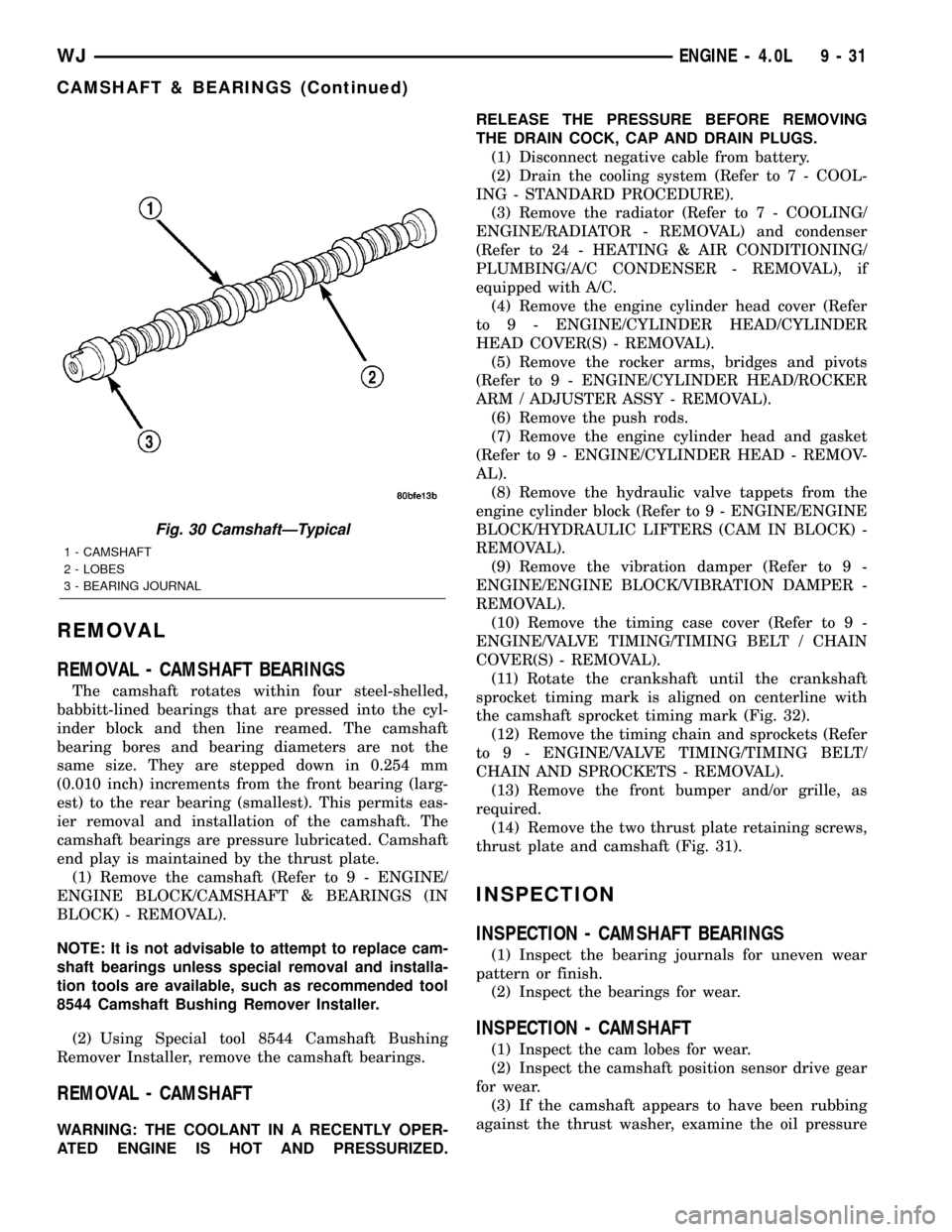
REMOVAL - CAMSHAFT BEARINGS
The camshaft rotates within four steel-shelled,
babbitt-lined bearings that are pressed into the cyl-
inder block and then line reamed. The camshaft
bearing bores and bearing diameters are not the
same size. They are stepped down in 0.254 mm
(0.010 inch) increments from the front bearing (larg-
est) to the rear bearing (smallest). This permits eas-
ier removal and installation of the camshaft. The
camshaft bearings are pressure lubricated. Camshaft
end play is maintained by the thrust plate.
(1) Remove the camshaft (Refer to 9 - ENGINE/
ENGINE BLOCK/CAMSHAFT & BEARINGS (IN
BLOCK) - REMOVAL).
NOTE: It is not advisable to attempt to replace cam-
shaft bearings unless special removal and installa-
tion tools are available, such as recommended tool
8544 Camshaft Bushing Remover Installer.
(2) Using Special tool 8544 Camshaft Bushing
Remover Installer, remove the camshaft bearings.
REMOVAL - CAMSHAFT
WARNING: THE COOLANT IN A RECENTLY OPER-
ATED ENGINE IS HOT AND PRESSURIZED.RELEASE THE PRESSURE BEFORE REMOVING
THE DRAIN COCK, CAP AND DRAIN PLUGS.
(1) Disconnect negative cable from battery.
(2) Drain the cooling system (Refer to 7 - COOL-
ING - STANDARD PROCEDURE).
(3) Remove the radiator (Refer to 7 - COOLING/
ENGINE/RADIATOR - REMOVAL) and condenser
(Refer to 24 - HEATING & AIR CONDITIONING/
PLUMBING/A/C CONDENSER - REMOVAL), if
equipped with A/C.
(4) Remove the engine cylinder head cover (Refer
to 9 - ENGINE/CYLINDER HEAD/CYLINDER
HEAD COVER(S) - REMOVAL).
(5) Remove the rocker arms, bridges and pivots
(Refer to 9 - ENGINE/CYLINDER HEAD/ROCKER
ARM / ADJUSTER ASSY - REMOVAL).
(6) Remove the push rods.
(7) Remove the engine cylinder head and gasket
(Refer to 9 - ENGINE/CYLINDER HEAD - REMOV-
AL).
(8) Remove the hydraulic valve tappets from the
engine cylinder block (Refer to 9 - ENGINE/ENGINE
BLOCK/HYDRAULIC LIFTERS (CAM IN BLOCK) -
REMOVAL).
(9) Remove the vibration damper (Refer to 9 -
ENGINE/ENGINE BLOCK/VIBRATION DAMPER -
REMOVAL).
(10) Remove the timing case cover (Refer to 9 -
ENGINE/VALVE TIMING/TIMING BELT / CHAIN
COVER(S) - REMOVAL).
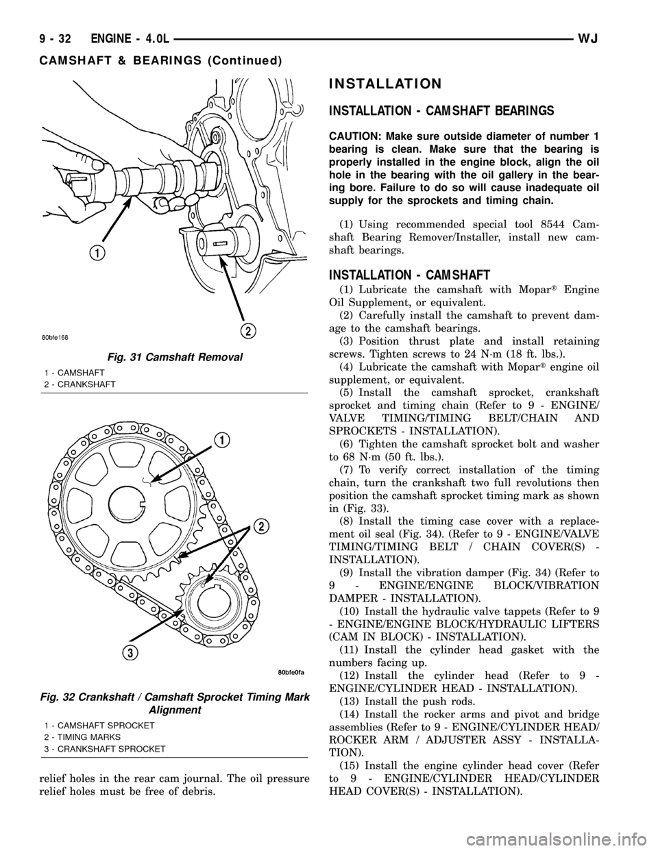
(11) Rotate the crankshaft until the crankshaft
sprocket timing mark is aligned on centerline with
the camshaft sprocket timing mark (Fig. 32).
(12) Remove the timing chain and sprockets (Refer
to 9 - ENGINE/VALVE TIMING/TIMING BELT/
CHAIN AND SPROCKETS - REMOVAL).
(13) Remove the front bumper and/or grille, as
required.
(14) Remove the two thrust plate retaining screws,
thrust plate and camshaft (Fig. 31).
INSPECTION
INSPECTION - CAMSHAFT BEARINGS
(1) Inspect the bearing journals for uneven wear
pattern or finish.
(2) Inspect the bearings for wear.
INSPECTION - CAMSHAFT
(1) Inspect the cam lobes for wear.
(2) Inspect the camshaft position sensor drive gear
for wear.
(3) If the camshaft appears to have been rubbing
against the thrust washer, examine the oil pressure
Fig. 30 CamshaftÐTypical
1 - CAMSHAFT
2 - LOBES
3 - BEARING JOURNAL
WJENGINE - 4.0L 9 - 31
CAMSHAFT & BEARINGS (Continued)
Page 1275 of 2199
relief holes in the rear cam journal. The oil pressure
relief holes must be free of debris.
INSTALLATION
INSTALLATION - CAMSHAFT BEARINGS
CAUTION: Make sure outside diameter of number 1
bearing is clean. Make sure that the bearing is
properly installed in the engine block, align the oil
hole in the bearing with the oil gallery in the bear-
ing bore. Failure to do so will cause inadequate oil
supply for the sprockets and timing chain.
(1) Using recommended special tool 8544 Cam-
shaft Bearing Remover/Installer, install new cam-
shaft bearings.
INSTALLATION - CAMSHAFT
(1) Lubricate the camshaft with MopartEngine
Oil Supplement, or equivalent.
(2) Carefully install the camshaft to prevent dam-
age to the camshaft bearings.
(3) Position thrust plate and install retaining
screws. Tighten screws to 24 N´m (18 ft. lbs.).
(4) Lubricate the camshaft with Mopartengine oil
supplement, or equivalent.
(5) Install the camshaft sprocket, crankshaft
sprocket and timing chain (Refer to 9 - ENGINE/
VALVE TIMING/TIMING BELT/CHAIN AND
SPROCKETS - INSTALLATION).
(6) Tighten the camshaft sprocket bolt and washer
to 68 N´m (50 ft. lbs.).
(7) To verify correct installation of the timing
chain, turn the crankshaft two full revolutions then
position the camshaft sprocket timing mark as shown
in (Fig. 33).
(8) Install the timing case cover with a replace-
ment oil seal (Fig. 34). (Refer to 9 - ENGINE/VALVE
TIMING/TIMING BELT / CHAIN COVER(S) -
INSTALLATION).
(9) Install the vibration damper (Fig. 34) (Refer to
9 - ENGINE/ENGINE BLOCK/VIBRATION
DAMPER - INSTALLATION).
(10) Install the hydraulic valve tappets (Refer to 9
- ENGINE/ENGINE BLOCK/HYDRAULIC LIFTERS
(CAM IN BLOCK) - INSTALLATION).
(11) Install the cylinder head gasket with the
numbers facing up.
(12) Install the cylinder head (Refer to 9 -
ENGINE/CYLINDER HEAD - INSTALLATION).
(13) Install the push rods.
(14) Install the rocker arms and pivot and bridge
assemblies (Refer to 9 - ENGINE/CYLINDER HEAD/
ROCKER ARM / ADJUSTER ASSY - INSTALLA-
TION).
(15) Install the engine cylinder head cover (Refer
to 9 - ENGINE/CYLINDER HEAD/CYLINDER
HEAD COVER(S) - INSTALLATION).
Fig. 31 Camshaft Removal
1 - CAMSHAFT
2 - CRANKSHAFT
Fig. 32 Crankshaft / Camshaft Sprocket Timing Mark
Alignment
1 - CAMSHAFT SPROCKET
2 - TIMING MARKS
3 - CRANKSHAFT SPROCKET
9 - 32 ENGINE - 4.0LWJ
CAMSHAFT & BEARINGS (Continued)
Page 1288 of 2199
PISTON SIZE CHART
CYLINDER BORE SIZE PISTON LETTER SIZE
98.438 - 98.448 mm
(3.8755 - 3.8759 in.)A
98.448 - 98.458 mm
(3.8759 - 3.8763 in.)B
98.458 - 98.468 mm
(3.8763 - 3.8767 in.)C
98.468 - 98.478 mm
(3.8767 - 3.8771 in.)D
98.478 - 98.488 mm
(3.8771 - 3.8775 in.)E
98.488 - 98.498 mm
(3.8775 - 3.8779 in.)F
REMOVAL
(1) Remove the engine cylinder head cover. (Refer
to 9 - ENGINE/CYLINDER HEAD/CYLINDER
HEAD COVER(S) - REMOVAL).
(2) Remove the rocker arms, bridges and pivots.
(3) Remove the push rods.
(4) Remove the engine cylinder head. (Refer to 9 -
ENGINE/CYLINDER HEAD - REMOVAL).
(5) Position the pistons one at a time near the bot-
tom of the stroke. Use a ridge reamer to remove theridge from the top end of the cylinder walls. Use a
protective cloth to collect the cuttings.
(6) Raise the vehicle.
(7) Drain the engine oil.
(8) Remove the oil pan and gasket. (Refer to 9 -
ENGINE/LUBRICATION/OIL PAN - REMOVAL).
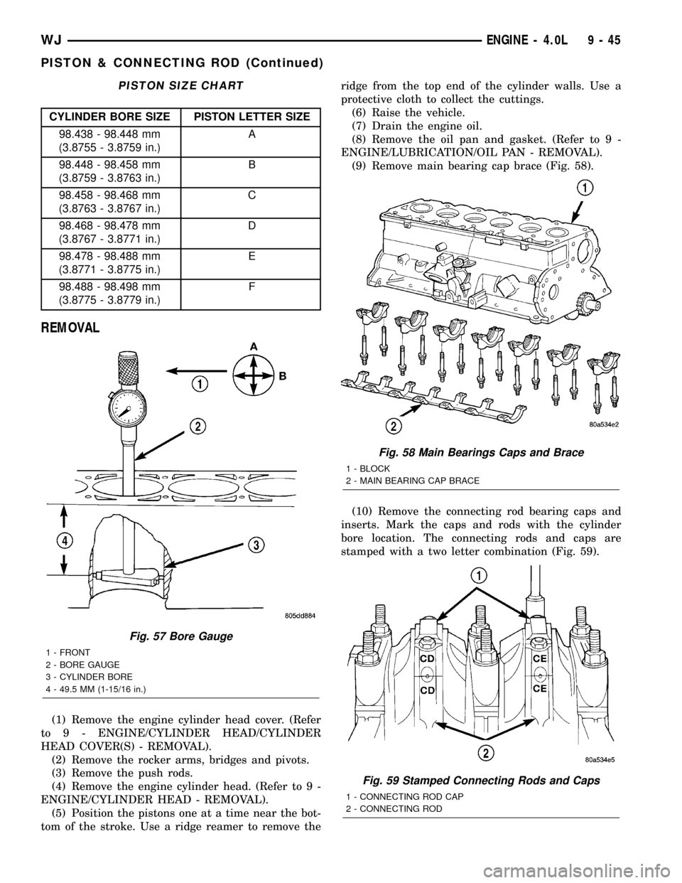
(9) Remove main bearing cap brace (Fig. 58).
(10) Remove the connecting rod bearing caps and
inserts. Mark the caps and rods with the cylinder
bore location. The connecting rods and caps are
stamped with a two letter combination (Fig. 59).
Fig. 57 Bore Gauge
1 - FRONT
2 - BORE GAUGE
3 - CYLINDER BORE
4 - 49.5 MM (1-15/16 in.)
Fig. 58 Main Bearings Caps and Brace
1 - BLOCK
2 - MAIN BEARING CAP BRACE
Fig. 59 Stamped Connecting Rods and Caps
1 - CONNECTING ROD CAP
2 - CONNECTING ROD
WJENGINE - 4.0L 9 - 45
PISTON & CONNECTING ROD (Continued)
Page 1290 of 2199
(12) Install the oil pan and gasket (Refer to 9 -
ENGINE/LUBRICATION/OIL PAN - INSTALLA-
TION).
(13) Lower the vehicle.
(14) Install the engine cylinder head (Refer to 9 -
ENGINE/CYLINDER HEAD - INSTALLATION),
push rods, rocker arms, bridges, pivots and engine
cylinder head cover(Refer to 9 - ENGINE/CYLINDER
HEAD/CYLINDER HEAD COVER(S) - INSTALLA-
TION).
(15) Fill the crankcase with engine oil.
PISTON RINGS
STANDARD PROCEDURE - PISTON RING
FITTING
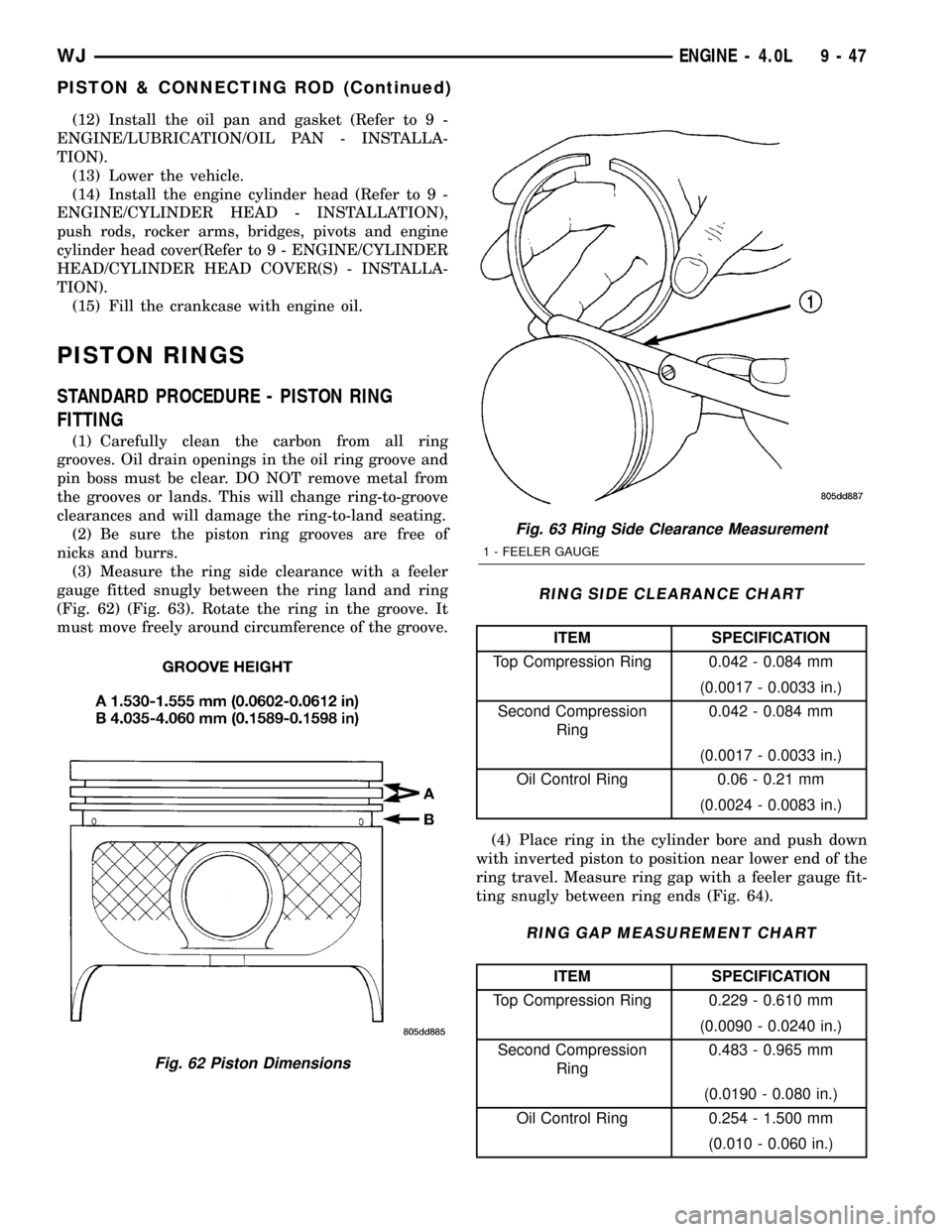
(1) Carefully clean the carbon from all ring
grooves. Oil drain openings in the oil ring groove and
pin boss must be clear. DO NOT remove metal from
the grooves or lands. This will change ring-to-groove
clearances and will damage the ring-to-land seating.
(2) Be sure the piston ring grooves are free of
nicks and burrs.
(3) Measure the ring side clearance with a feeler
gauge fitted snugly between the ring land and ring
(Fig. 62) (Fig. 63). Rotate the ring in the groove. It
must move freely around circumference of the groove.
RING SIDE CLEARANCE CHART
ITEM SPECIFICATION
Top Compression Ring 0.042 - 0.084 mm
(0.0017 - 0.0033 in.)
Second Compression
Ring0.042 - 0.084 mm
(0.0017 - 0.0033 in.)
Oil Control Ring 0.06 - 0.21 mm
(0.0024 - 0.0083 in.)
(4) Place ring in the cylinder bore and push down
with inverted piston to position near lower end of the
ring travel. Measure ring gap with a feeler gauge fit-
ting snugly between ring ends (Fig. 64).
RING GAP MEASUREMENT CHART
ITEM SPECIFICATION
Top Compression Ring 0.229 - 0.610 mm
(0.0090 - 0.0240 in.)
Second Compression
Ring0.483 - 0.965 mm
(0.0190 - 0.080 in.)
Oil Control Ring 0.254 - 1.500 mm
(0.010 - 0.060 in.)
Fig. 62 Piston Dimensions
Fig. 63 Ring Side Clearance Measurement
1 - FEELER GAUGE
WJENGINE - 4.0L 9 - 47
PISTON & CONNECTING ROD (Continued)
Page 1298 of 2199
(10) Place a piece of wood (2 x 2) between the jack
stand and the engine vibration damper.
(11) Remove the engine mount through bolts.
(12) Using the jack stand, raise the engine until
adequate clearance is obtained to remove the oil pan.
(13) Remove transmission oil cooling lines (if
equipped) and oxygen sensor wiring supports that
are attached to the oil pan studs.
(14) Remove the oil pan bolts and studs. Carefully
slide the oil pan and gasket to the rear. If equipped
with an oil level sensor, take care not to damage the
sensor.
INSTALLATION
(1) Clean the block and pan gasket surfaces.
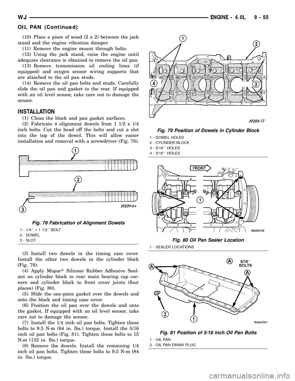
(2) Fabricate 4 alignment dowels from 1 1/2 x 1/4
inch bolts. Cut the head off the bolts and cut a slot
into the top of the dowel. This will allow easier
installation and removal with a screwdriver (Fig. 78).
(3) Install two dowels in the timing case cover.
Install the other two dowels in the cylinder block
(Fig. 79).
(4) Apply MopartSilicone Rubber Adhesive Seal-
ant on cylinder block to rear main bearing cap cor-
ners and cylinder block to front cover joints (four
places) (Fig. 80).
(5) Slide the one-piece gasket over the dowels and
onto the block and timing case cover.
(6) Position the oil pan over the dowels and onto
the gasket. If equipped with an oil level sensor, take
care not to damage the sensor.
(7) Install the 1/4 inch oil pan bolts. Tighten these
bolts to 9.5 N´m (84 in. lbs.) torque. Install the 5/16
inch oil pan bolts (Fig. 81). Tighten these bolts to 15
N´m (132 in. lbs.) torque.
(8) Remove the dowels. Install the remaining 1/4
inch oil pan bolts. Tighten these bolts to 9.5 N´m (84
in. lbs.) torque.
Fig. 78 Fabrication of Alignment Dowels
1 - 1/488ý 1 1/288BOLT
2 - DOWEL
3 - SLOT
Fig. 79 Position of Dowels in Cylinder Block
1 - DOWEL HOLES
2 - CYLINDER BLOCK
3 - 5/1688HOLES
4 - 5/1688HOLES
Fig. 80 Oil Pan Sealer Location
1 - SEALER LOCATIONS
Fig. 81 Position of 5/16 inch Oil Pan Bolts
1 - OIL PAN
2 - OIL PAN DRAIN PLUG
WJENGINE - 4.0L 9 - 55
OIL PAN (Continued)