tow bar JEEP GRAND CHEROKEE 2003 WJ / 2.G User Guide
[x] Cancel search | Manufacturer: JEEP, Model Year: 2003, Model line: GRAND CHEROKEE, Model: JEEP GRAND CHEROKEE 2003 WJ / 2.GPages: 2199, PDF Size: 76.01 MB
Page 646 of 2199
along the left roof side rail to the rear of the vehicle.
At the rear of the vehicle, the headliner hose is
routed above the headliner and along the upper lift-
gate opening panel toward the right side of the vehi-
cle. The headliner hose then passes through a hole
with a rubber grommet in the upper liftgate opening
panel and through another hole with a rubber grom-
met into the upper inner liftgate panel to the rear
washer nozzle.
Washer hose is available for service only as roll
stock, which must then be cut to length. The head-
liner washer hose is integral to the headliner unit
and, if faulty or damaged, the headliner unit must be
replaced. The molded plastic washer hose fittings
cannot be repaired. If these fittings are faulty or
damaged, they must be replaced.
OPERATION
Washer fluid in the washer reservoir is pressurized
and fed by the rear washer pump/motor through the
rear washer system plumbing and fittings to the rear
washer nozzle on the liftgate outer panel above the
liftgate glass. Whenever routing the washer hose or a
wire harness containing a washer hose, it must be
routed away from hot, sharp, or moving parts; and,
sharp bends that might pinch the hose must be
avoided.
REAR WASHER NOZZLE
DESCRIPTION
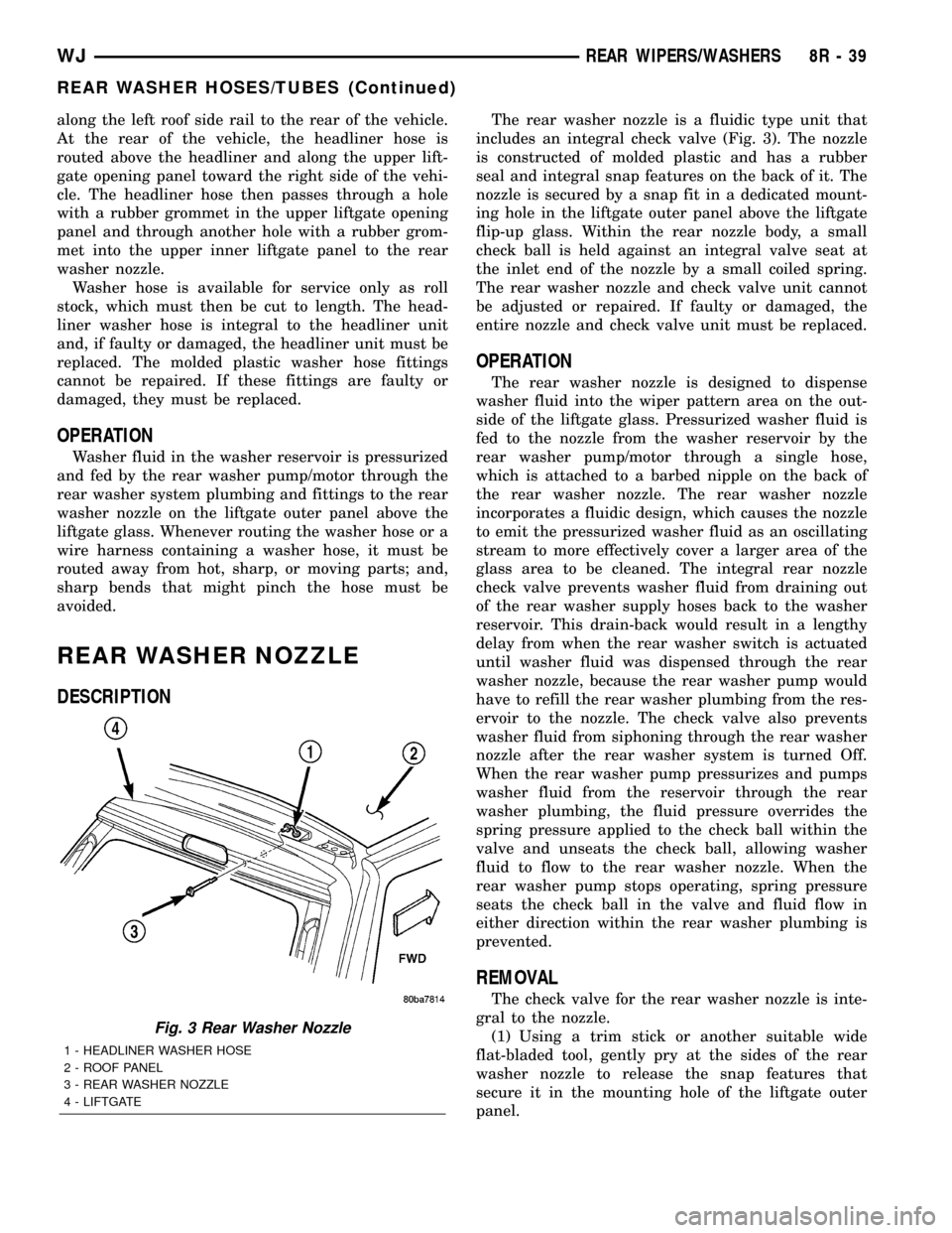
The rear washer nozzle is a fluidic type unit that
includes an integral check valve (Fig. 3). The nozzle
is constructed of molded plastic and has a rubber
seal and integral snap features on the back of it. The
nozzle is secured by a snap fit in a dedicated mount-
ing hole in the liftgate outer panel above the liftgate
flip-up glass. Within the rear nozzle body, a small
check ball is held against an integral valve seat at
the inlet end of the nozzle by a small coiled spring.
The rear washer nozzle and check valve unit cannot
be adjusted or repaired. If faulty or damaged, the
entire nozzle and check valve unit must be replaced.
OPERATION
The rear washer nozzle is designed to dispense
washer fluid into the wiper pattern area on the out-
side of the liftgate glass. Pressurized washer fluid is
fed to the nozzle from the washer reservoir by the
rear washer pump/motor through a single hose,
which is attached to a barbed nipple on the back of
the rear washer nozzle. The rear washer nozzle
incorporates a fluidic design, which causes the nozzle
to emit the pressurized washer fluid as an oscillating
stream to more effectively cover a larger area of the
glass area to be cleaned. The integral rear nozzle
check valve prevents washer fluid from draining out
of the rear washer supply hoses back to the washer
reservoir. This drain-back would result in a lengthy
delay from when the rear washer switch is actuated
until washer fluid was dispensed through the rear
washer nozzle, because the rear washer pump would
have to refill the rear washer plumbing from the res-
ervoir to the nozzle. The check valve also prevents
washer fluid from siphoning through the rear washer
nozzle after the rear washer system is turned Off.
When the rear washer pump pressurizes and pumps
washer fluid from the reservoir through the rear
washer plumbing, the fluid pressure overrides the
spring pressure applied to the check ball within the
valve and unseats the check ball, allowing washer
fluid to flow to the rear washer nozzle. When the
rear washer pump stops operating, spring pressure
seats the check ball in the valve and fluid flow in
either direction within the rear washer plumbing is
prevented.
REMOVAL
The check valve for the rear washer nozzle is inte-
gral to the nozzle.
(1) Using a trim stick or another suitable wide
flat-bladed tool, gently pry at the sides of the rear
washer nozzle to release the snap features that
secure it in the mounting hole of the liftgate outer
panel.
Fig. 3 Rear Washer Nozzle
1 - HEADLINER WASHER HOSE
2 - ROOF PANEL
3 - REAR WASHER NOZZLE
4 - LIFTGATE
WJREAR WIPERS/WASHERS 8R - 39
REAR WASHER HOSES/TUBES (Continued)
Page 647 of 2199
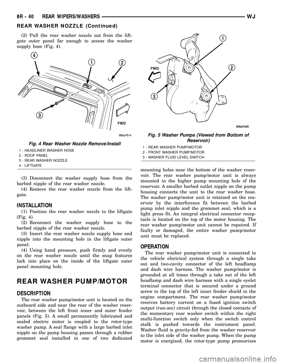
(2) Pull the rear washer nozzle out from the lift-
gate outer panel far enough to access the washer
supply hose (Fig. 4).
(3) Disconnect the washer supply hose from the
barbed nipple of the rear washer nozzle.
(4) Remove the rear washer nozzle from the lift-
gate.
INSTALLATION
(1) Position the rear washer nozzle to the liftgate
(Fig. 4).
(2) Reconnect the washer supply hose to the
barbed nipple of the rear washer nozzle.
(3) Insert the rear washer nozzle supply hose and
nipple into the mounting hole in the liftgate outer
panel.
(4) Using hand pressure, push firmly and evenly
on the rear washer nozzle until the snap features
lock into place on the inside of the liftgate outer
panel mounting hole.
REAR WASHER PUMP/MOTOR
DESCRIPTION
The rear washer pump/motor unit is located on the
outboard side and near the rear of the washer reser-
voir, between the left front inner and outer fender
panels (Fig. 5). A small permanently lubricated and
sealed electric motor is coupled to the rotor-type
washer pump. A seal flange with a large barbed inlet
nipple on the pump housing passes through a rubber
grommet seal installed in one of two dedicatedmounting holes near the bottom of the washer reser-
voir. The rear washer pump/motor unit is always
mounted in the higher pump mounting hole of the
reservoir. A smaller barbed outlet nipple on the pump
housing connects the unit to the rear washer hose.
The washer pump/motor unit is retained on the res-
ervoir by the interference fit between the barbed
pump inlet nipple and the grommet seal, which is a
light press fit. An integral electrical connector recep-
tacle is located on the top of the motor housing. The
rear washer pump/motor unit cannot be repaired. If
faulty or damaged, the entire washer pump/motor
unit must be replaced.
OPERATION
The rear washer pump/motor unit is connected to
the vehicle electrical system through a single take
out and two-cavity connector of the left headlamp
and dash wire harness. The washer pump/motor is
grounded at all times through a take out of the left
headlamp and dash wire harness with a single eyelet
terminal connector that is secured under a ground
screw to the top of the left inner fender shield in the
engine compartment. The rear washer pump/motor
receives battery current on a fused ignition switch
output (run-acc) circuit through the closed contacts of
the momentary rear washer switch within the right
multi-function switch only when the switch control
stalk is pushed towards the instrument panel.
Washer fluid is gravity-fed from the washer reservoir
to the inlet side of the washer pump. When the pump
motor is energized, the rotor-type pump pressurizes
Fig. 4 Rear Washer Nozzle Remove/Install
1 - HEADLINER WASHER HOSE
2 - ROOF PANEL
3 - REAR WASHER NOZZLE
4 - LIFTGATE
Fig. 5 Washer Pumps (Viewed from Bottom of
Reservoir)
1 - REAR WASHER PUMP/MOTOR
2 - FRONT WASHER PUMP/MOTOR
3 - WASHER FLUID LEVEL SWITCH
8R - 40 REAR WIPERS/WASHERSWJ
REAR WASHER NOZZLE (Continued)
Page 706 of 2199
8W-12 JUNCTION BLOCK
Component PageA/C Compressor Clutch Relay................8W-12-18
Accessory Delay Relay.....................8W-12-25
Adjustable Pedals Module..................8W-12-11
Airbag Control Module....................8W-12-25
Auto Shut Down Relay....................8W-12-18
Automatic Day/Night Mirror.................8W-12-23
Automatic Headlamp Light Sensor/VTSS LED......8W-12-15
Automatic Zone Control Module..........8W-12-15, 17, 22
Back-Up Lamp Relay.....................8W-12-22
Body Control Module . . . 8W-12-10, 12, 13, 15, 17, 20, 23, 24, 25,
26, 27, 28, 29, 30, 31, 35, 36
Brake Lamp Switch......................8W-12-24
Cargo Lamp......................8W-12-16, 24, 27
Cigar Lighter..........................8W-12-17
Cigar Lighter Relay....................8W-12-17, 26
Circuit Breaker No. 1...................8W-12-28, 29
Circuit Breaker No. 2......................8W-12-9
Clockspring...........................8W-12-31
Combination Flasher............8W-12-10, 22, 27, 32, 35
Controller Antilock Brake..................8W-12-21
Data Link Connector.....................8W-12-10
Driver Door Module......................8W-12-34
Driver Heated Seat Switch..................8W-12-22
Driver Lumbar Switch.....................8W-12-9
Driver Power Seat Switch...................8W-12-9
Electric Brake..........................8W-12-21
Engine Control Module....................8W-12-19
Engine Starter Motor Relay.................8W-12-26
EVAP/Purge Solenoid.....................8W-12-18
Fog Lamp Relay........................8W-12-24
Front Power Outlet......................8W-12-11
Front Wiper Motor....................8W-12-28, 29
Fuel Pump Relay........................8W-12-18
Fuse 2..............................8W-12-17
Fuse 3............................8W-12-10, 20
Fuse 4..............................8W-12-10
Fuse 5..............................8W-12-11
Fuse 6............................8W-12-12, 13
Fuse 7..............................8W-12-15
Fuse 8..............................8W-12-16
Fuse 9..............................8W-12-11
Fuse 10..............................8W-12-11
Fuse 11..............................8W-12-17
Fuse 12.......................8W-12-18, 19, 21, 34
Fuse 14..............................8W-12-20
Fuse 15.........................8W-12-11, 15, 20
Fuse 16..............................8W-12-10
Fuse 17..............................8W-12-10
Fuse 18...........................8W-12-21, 34
Fuse 19..............................8W-12-21
Fuse 20..............................8W-12-22
Fuse 21...........................8W-12-18, 19
Fuse 22..............................8W-12-23
Fuse 23..............................8W-12-24
Fuse 24..............................8W-12-24
Fuse 25..............................8W-12-25
Fuse 26..............................8W-12-17
Fuse 27..............................8W-12-36
Fuse 28..............................8W-12-26
Fuse 29..............................8W-12-26
Fuse 30..............................8W-12-26
Fuse 31..............................8W-12-26
Fuse 32..............................8W-12-25
Fuse 33..............................8W-12-25
G200...............................8W-12-35
Glove Box Lamp........................8W-12-16
Headlamp Leveling Switch...............8W-12-12, 13
High Beam Relay........................8W-12-10
Horn Relay...........................8W-12-31
Horn Switch...........................8W-12-31
Instrument Cluster..................8W-12-10, 23, 32
Intrusion Transceiver Module................8W-12-16
Junction Block.........8W-12-2, 3, 9, 10, 11, 12, 13, 15, 16,
17, 18, 19, 20, 21, 22, 23, 24, 25,
26, 27, 28, 29, 30, 31, 32, 34, 35, 36Component PageLeft Courtesy Lamp......................8W-12-16
Left Door Handle Courtesy Lamp.........8W-12-16, 24, 30
Left Fog Lamp.........................8W-12-24
Left Front Park Lamp.....................8W-12-14
Left Front Park/Turn Signal Lamp...........8W-12-14, 33
Left Front Side Marker Lamp..............8W-12-14, 33
Left Front Turn Signal Lamp................8W-12-33
Left Headlamp Leveling Motor...............8W-12-14
Left High Beam Headlamp..................8W-12-10
Left Liftgate Ajar Switch...................8W-12-30
Left Low Beam Headlamp..................8W-12-20
Left Multi-Function Switch...............8W-12-10, 35
Left Rear Door Lock Motor/Ajar Switch..........8W-12-27
Left Rear Lamp Assembly...........8W-12-12, 13, 27, 36
Left Side Repeater Lamp...................8W-12-32
Left Visor/Vanity Lamp..................8W-12-16, 30
License Lamp No. 1....................8W-12-12, 13
License Lamp No. 2....................8W-12-12, 13
Liftgate Flip-Up Ajar Switch.................8W-12-30
Liftgate Flip-Up Push Button Switch...........8W-12-16
Liftgate Power Lock Motor..................8W-12-16
Low Beam Relay........................8W-12-20
Low Beam/Daytime Running Lamp Relay.........8W-12-20
Manual Temperature Control..............8W-12-17, 22
Overhead Map/Courtesy Lamp...........8W-12-16, 24, 30
Park Lamp Relay.....................8W-12-12, 13
Park/Neutral Position Switch................8W-12-22
Passenger Door Module....................8W-12-34
Passenger Heated Seat Switch...............8W-12-22
Passenger Lumbar Switch...................8W-12-9
Passenger Power Seat Switch.................8W-12-9
Power Amplifier.........................8W-12-11
Power Connector........................8W-12-11
Power Distribution Center....8W-12-10, 11, 15, 17, 20, 21, 34
Powertrain Control Module.................8W-12-18
Radio.............................8W-12-11, 26
Rain Sensor...........................8W-12-25
Rear Window Defogger....................8W-12-17
Rear Window Defogger Relay................8W-12-17
Rear Wiper Motor.....................8W-12-16, 30
Remote Keyless Module....................8W-12-15
Right Courtesy Lamp.....................8W-12-16
Right Door Handle Courtesy Lamp........8W-12-16, 24, 30
Right Fog Lamp........................8W-12-24
Right Front Park Lamp....................8W-12-14
Right Front Park/Turn Signal Lamp..........8W-12-14, 33
Right Front Side Marker Lamp.............8W-12-14, 33
Right Front Turn Signal Lamp...............8W-12-33
Right Headlamp Leveling Motor..............8W-12-14
Right High Beam Headlamp.................8W-12-10
Right Liftgate Ajar Switch..................8W-12-30
Right Low Beam Headlamp.................8W-12-20
Right Multi-Function Switch.................8W-12-26
Right Rear Lamp Assembly..........8W-12-12, 13, 32, 36
Right Side Repeater Lamp..................8W-12-32
Right Visor/Vanity Lamp.................8W-12-16, 30
Seat Module...........................8W-12-9
Sentry Key Immobilizer Module............8W-12-15, 23
Shifter Assembly......................8W-12-18, 19
Siren...............................8W-12-15
Sunroof Control Module....................8W-12-25
Temperature Valve Actuator.................8W-12-22
Trailer Tow Brake Lamp Relay...............8W-12-21
Trailer Tow Circuit Breaker.................8W-12-17
Trailer Tow Connector.....................8W-12-12
Trailer Tow Left Turn Relay.................8W-12-27
Trailer Tow Right Turn Relay................8W-12-32
Transmission Control Module..............8W-12-18, 26
Transmission Solenoid/TRS Assembly...........8W-12-22
Underhood Lamp........................8W-12-15
Vehicle Information Center...............8W-12-16, 23
Wiper High/Low Relay..................8W-12-28, 29
Wiper On/Off Relay....................8W-12-28, 29
WJ8W-12 JUNCTION BLOCK 8W - 12 - 1
Page 742 of 2199
8W-15 GROUND DISTRIBUTION
Component Page
A/C Compressor Clutch.................. 8W-15-4
Adjustable Pedals Module............. 8W-15-17, 21
Airbag Control Module.................. 8W-15-16
Ash Receiver Lamp.................... 8W-15-14
Automatic Day/Night Mirror.............. 8W-15-19
Automatic Zone Control Module........... 8W-15-15
Battery............................ 8W-15-2, 3
Blower Motor Controller................. 8W-15-15
Body Control Module.............. 8W-15-12, 13, 15
Brake Lamp Switch................. 8W-15-17, 22
Center High Mounted Stop Lamp.......... 8W-15-20
Cigar Lighter........................ 8W-15-14
Cigar Lighter Relay.................... 8W-15-12
Controller Antilock Brake................ 8W-15-12
Coolant Level Sensor............... 8W-15-9, 10, 11
Crankcase Heater...................... 8W-15-4
Data Link Connector.................. 8W-15-2, 3
Driver Cylinder Lock Switch.............. 8W-15-16
Driver Door Lock Motor/Ajar Switch........ 8W-15-16
Driver Door Module.................... 8W-15-16
Driver Heated Seat Switch............... 8W-15-14
Driver Lumbar Switch............... 8W-15-18, 21
Driver Power Seat Switch............. 8W-15-18, 21
Driver Rear Power Window Switch....... 8W-15-18, 21
Electric Brake........................ 8W-15-17
Electronic Speed Control Servo.......... 8W-15-9, 10
Engine Control Module.................. 8W-15-3
Front Power Outlet.................... 8W-15-14
Front Washer Pump................... 8W-15-6, 7
Front Wiper Motor.................... 8W-15-6, 7
Fuel Pump Module.................... 8W-15-19
G100............................. 8W-15-2, 3
G101............................. 8W-15-2, 3
G102............................... 8W-15-2
G103............................. 8W-15-2, 3
G104............................... 8W-15-4
G105............................... 8W-15-4
G106............................. 8W-15-6, 7
G107.............................. 8W-15-12
G108.......................... 8W-15-9, 10, 11
G200......................... 8W-15-13, 14, 15
G201.............................. 8W-15-16
G300......................... 8W-15-16, 17, 18
G301......................... 8W-15-19, 21, 22
Headlamp Leveling Switch............... 8W-15-15
Hood Ajar Switch..................... 8W-15-6, 7
Horn No. 1...................... 8W-15-9, 10, 11
Horn No. 2...................... 8W-15-9, 10, 11
Hydraulic Cooling Module........... 8W-15-9, 10, 11
Ignition Switch....................... 8W-15-15
Instrument Cluster.................. 8W-15-13, 14
Intake Port Swirl Actuator................ 8W-15-3
Intrusion Transceiver Module.......... 8W-15-21, 22
Junction Block.................. 8W-15-12, 13, 15
Left Fog Lamp...................... 8W-15-6, 7
Left Front Park Lamp................... 8W-15-5
Left Front Park/Turn Signal Lamp.......... 8W-15-5
Left Front Turn Signal Lamp.............. 8W-15-5
Left Headlamp Leveling Motor............. 8W-15-5
Left High Beam Headlamp................ 8W-15-5
Component Page
Left Liftgate Ajar Switch................ 8W-15-20
Left Low Beam Headlamp................ 8W-15-5
Left Multi-Function Switch............... 8W-15-15
Left Rear Door Lock Motor/Ajar Switch.... 8W-15-21, 22
Left Rear Lamp Assembly............... 8W-15-19
Left Side Repeater Lamp............... 8W-15-6, 7
License Lamp No. 1.................... 8W-15-20
License Lamp No. 2.................... 8W-15-20
Liftgate Flip-Up Ajar Switch.............. 8W-15-20
Liftgate Flip-Up Release Solenoid.......... 8W-15-20
Line Pressure Sensor.................... 8W-15-2
Low Beam/Daytime Running Lamp Relay.... 8W-15-12
Manual Temperature Control........... 8W-15-13, 15
Oxygen Sensor 1/2 Downstream............ 8W-15-4
Oxygen Sensor 2/2 Downstream............ 8W-15-4
Park Lamp Relay..................... 8W-15-12
Passenger Door Lock Motor/Ajar Switch...... 8W-15-16
Passenger Door Module................. 8W-15-16
Passenger Heated Seat Switch............ 8W-15-14
Passenger Lumbar Switch............. 8W-15-17, 22
Passenger Power Seat Switch.......... 8W-15-17, 22
Passenger Rear Power Window Switch.... 8W-15-16, 22
Power Amplifier.................... 8W-15-17, 18
Power Connector...................... 8W-15-15
Powertrain Control Module............... 8W-15-2
Radio........................... 8W-15-17, 18
Rain Sensor....................... 8W-15-21, 22
Rear Power Outlet.................. 8W-15-17, 18
Rear Washer Pump................... 8W-15-6, 7
Rear Window Defogger.................. 8W-15-20
Rear Wiper Motor..................... 8W-15-20
Remote Keyless Module................. 8W-15-16
Right Fog Lamp.................. 8W-15-9, 10, 11
Right Front Park Lamp.................. 8W-15-8
Right Front Park/Turn Signal Lamp......... 8W-15-8
Right Front Turn Signal Lamp............. 8W-15-8
Right Headlamp Leveling Motor............ 8W-15-8
Right High Beam Headlamp............... 8W-15-8
Right Low Beam Headlamp............... 8W-15-8
Right Rear Door Lock Motor/Ajar Switch . . 8W-15-16, 18
Right Rear Lamp Assembly............ 8W-15-17, 18
Right Side Repeater Lamp........... 8W-15-9, 10, 11
Seat Module...................... 8W-15-18, 21
Sentry Key Immobilizer Module........... 8W-15-13
Shifter Assembly................... 8W-15-14, 15
Siren............................. 8W-15-6, 7
Sunroof Control Module................. 8W-15-19
Sunroof Motor........................ 8W-15-19
Sunroof Switch....................... 8W-15-19
Temperature Valve Actuator.............. 8W-15-13
Trailer Tow Brake Lamp Relay............ 8W-15-19
Trailer Tow Connector.................. 8W-15-19
Trailer Tow Left Turn Relay.............. 8W-15-19
Trailer Tow Right Turn Relay............. 8W-15-19
Transmission Control Module.............. 8W-15-2
Transmission Control Relay............ 8W-15-9, 10
Underhood Lamp..................... 8W-15-6, 7
Vehicle Information Center............ 8W-15-21, 22
Viscous/Cabin Heater................... 8W-15-4
Washer Fluid Level Switch.............. 8W-15-6, 7
WJ8W-15 GROUND DISTRIBUTION 8W - 15 - 1
Page 1051 of 2199
Component Page
LIFTGATE FLIP-UP PUSH
BUTTON SWITCH................ 8W-80-97
LIFTGATE FLIP-UP RELEASE
SOLENOID...................... 8W-80-97
LIFTGATE POWER LOCK MOTOR..... 8W-80-97
LINE PRESSURE SENSOR (4.7L)...... 8W-80-98
MANIFOLD ABSOLUTE PRESSURE
SENSOR (4.0L)................... 8W-80-98
MANIFOLD ABSOLUTE PRESSURE
SENSOR (4.7L)................... 8W-80-98
MANUAL TEMPERATURE
CONTROL C1 (MTC).............. 8W-80-98
MANUAL TEMPERATURE
CONTROL C2 (MTC).............. 8W-80-99
MASS AIR FLOW SENSOR (DIESEL) . . . 8W-80-99
MODE DOOR MOTOR/ACTUATOR
(AZC).......................... 8W-80-99
NEEDLE MOVEMENT SENSOR
(DIESEL)....................... 8W-80-99
OUTPUT SPEED SENSOR (4.0L)...... 8W-80-99
OUTPUT SPEED SENSOR (4.7L)..... 8W-80-100
OVERHEAD MAP/COURTESY LAMP . . 8W-80-100
OXYGEN SENSOR 1/1 UPSTREAM.... 8W-80-100
OXYGEN SENSOR 1/2 DOWNSTREAM . 8W-80-100
OXYGEN SENSOR 2/1 UPSTREAM.... 8W-80-100
OXYGEN SENSOR 2/2
DOWNSTREAM................. 8W-80-101
PARK/NEUTRAL POSITION SWITCH
(4.0L).......................... 8W-80-101
PARK/NEUTRAL POSITION SWITCH
(DIESEL)...................... 8W-80-101
PASSENGER AIRBAG.............. 8W-80-101
PASSENGER BLEND DOOR
MOTOR/ACTUATOR (LHD) (AZC) . . . 8W-80-101
PASSENGER BLEND DOOR
MOTOR/ACTUATOR (RHD) (AZC) . . . 8W-80-102
PASSENGER CURTAIN AIRBAG...... 8W-80-102
PASSENGER DOOR LOCK MOTOR/AJAR
SWITCH....................... 8W-80-102
PASSENGER DOOR MODULE C1..... 8W-80-102
PASSENGER DOOR MODULE C2..... 8W-80-103
PASSENGER FRONT DOOR
COURTESY LAMP............... 8W-80-103
PASSENGER FRONT POWER
WINDOW MOTOR............... 8W-80-103
PASSENGER HEATED SEAT BACK
(PREMIUM I/III)................. 8W-80-103
PASSENGER HEATED SEAT CUSHION
(PREMIUM I/III)................. 8W-80-104
PASSENGER HEATED SEAT SWITCH . 8W-80-104
PASSENGER LUMBAR MOTOR
(MIDLINE/PREMIUM)............ 8W-80-104
PASSENGER LUMBAR SWITCH
(MIDLINE/PREMIUM)............ 8W-80-104
PASSENGER POWER MIRROR....... 8W-80-105Component Page
PASSENGER POWER SEAT FRONT
RISER MOTOR.................. 8W-80-105
PASSENGER POWER SEAT
HORIZONTAL MOTOR........... 8W-80-105
PASSENGER POWER SEAT REAR
RISER MOTOR.................. 8W-80-105
PASSENGER POWER SEAT RECLINER
MOTOR (MIDLINE/PREMIUM)..... 8W-80-106
PASSENGER POWER SEAT SWITCH
(MIDLINE/PREMIUM)............ 8W-80-106
PASSENGER REAR POWER
WINDOW MOTOR............... 8W-80-106
PASSENGER REAR POWER
WINDOW SWITCH............... 8W-80-106
PASSENGER SEAT BELT SWITCH.... 8W-80-106
PASSENGER SIDE IMPACT
SENSOR....................... 8W-80-107
POWER AMPLIFIER C1
(PREMIUM RADIO).............. 8W-80-107
POWER AMPLIFIER C2
(PREMIUM RADIO).............. 8W-80-107
POWER CONNECTOR.............. 8W-80-108
POWERTRAIN CONTROL
MODULE C1 (GAS).............. 8W-80-108
POWERTRAIN CONTROL
MODULE C2 (GAS).............. 8W-80-109
POWERTRAIN CONTROL
MODULE C3 (GAS).............. 8W-80-110
RADIATOR FAN MOTOR............ 8W-80-110
RADIATOR FAN RELAY............. 8W-80-111
RADIO C1........................ 8W-80-111
RADIO C2........................ 8W-80-111
RAIN SENSOR (AUTOWIPE)......... 8W-80-112
REAR POWER OUTLET............. 8W-80-112
REAR WASHER PUMP.............. 8W-80-112
REAR WIPER MOTOR.............. 8W-80-112
RECIRCULATION DOOR
MOTOR/ACTUATOR (AZC)......... 8W-80-112
RED BRAKE WARNING INDICATOR
SWITCH....................... 8W-80-113
REMOTE KEYLESS MODULE
(JAPAN)....................... 8W-80-113
RIGHT COURTESY LAMP........... 8W-80-113
RIGHT DOOR HANDLE
COURTESY LAMP............... 8W-80-113
RIGHT FOG LAMP................. 8W-80-113
RIGHT FRONT DOOR SPEAKER..... 8W-80-114
RIGHT FRONT IMPACT SENSOR..... 8W-80-114
RIGHT FRONT PARK LAMP......... 8W-80-114
RIGHT FRONT PARK/TURN SIGNAL LAMP
(EXCEPT BUILT-UP-EXPORT)...... 8W-80-114
RIGHT FRONT SIDE MARKER LAMP
(EXCEPT BUILT-UP-EXPORT)...... 8W-80-115
RIGHT FRONT TURN SIGNAL LAMP
(BUILT-UP-EXPORT)............. 8W-80-115
8W - 80 - 4 8W-80 CONNECTOR PIN-OUTWJ
Page 1234 of 2199
(9) Remove the PDC and the right headlamp and
dash wire harness from the engine compartment as a
unit.
DISASSEMBLY
POWER DISTRIBUTION CENTER DISASSEMBLY
PDC HOUSING LOWER COVER REMOVAL
The Power Distribution Center (PDC) cover, the
PDC housing lower cover, the PDC relay wedges, the
PDC relay cassettes and the PDC B(+) terminal stud
module are available for service replacement. The
PDC cover can be simply unlatched and removed
from the PDC housing without the PDC being
removed or disassembled. Service of the remaining
PDC components requires that the PDC be removed
from its mounting and disassembled. Refer toWiring
Repairin Wiring Diagrams for the location of the
wiring repair procedures.
(1) Remove the battery from the battery support.
Refer toBattery Systemfor the location of the bat-
tery removal procedures.
(2) Unlatch and remove the cover from the PDC.
(3) Remove the two nuts that secure the two-holed
eyelet of the battery wire harness PDC take out to
the B(+) terminal studs near the front of the PDC.
(4) Remove the battery wire harness PDC take out
eyelet from the two PDC B(+) terminal studs.
(5) Disengage the latches on the PDC housing
mounts from the tabs on the PDC mounting stan-
chions on the battery support, and pull the PDC
housing upward to disengage the mounts from the
stanchions.
(6) Where the right headlamp and dash wire har-
ness exits the PDC, remove the tape that secures the
wire harness to the trough formation on the PDC
housing lower cover.
(7) Using a trim stick or another suitable wide
flat-bladed tool, gently pry the latches on each side
and the front of the PDC housing that secure the
housing lower cover to the PDC and remove the
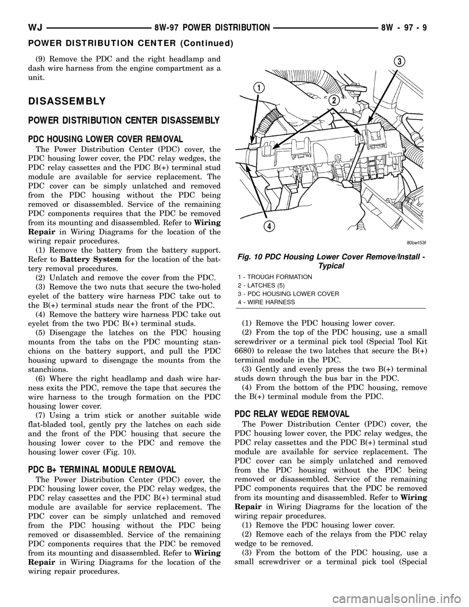
housing lower cover (Fig. 10).
PDC B+ TERMINAL MODULE REMOVAL
The Power Distribution Center (PDC) cover, the
PDC housing lower cover, the PDC relay wedges, the
PDC relay cassettes and the PDC B(+) terminal stud
module are available for service replacement. The
PDC cover can be simply unlatched and removed
from the PDC housing without the PDC being
removed or disassembled. Service of the remaining
PDC components requires that the PDC be removed
from its mounting and disassembled. Refer toWiring
Repairin Wiring Diagrams for the location of the
wiring repair procedures.(1) Remove the PDC housing lower cover.
(2) From the top of the PDC housing, use a small
screwdriver or a terminal pick tool (Special Tool Kit
6680) to release the two latches that secure the B(+)
terminal module in the PDC.
(3) Gently and evenly press the two B(+) terminal
studs down through the bus bar in the PDC.
(4) From the bottom of the PDC housing, remove
the B(+) terminal module from the PDC.
PDC RELAY WEDGE REMOVAL
The Power Distribution Center (PDC) cover, the
PDC housing lower cover, the PDC relay wedges, the
PDC relay cassettes and the PDC B(+) terminal stud
module are available for service replacement. The
PDC cover can be simply unlatched and removed
from the PDC housing without the PDC being
removed or disassembled. Service of the remaining
PDC components requires that the PDC be removed
from its mounting and disassembled. Refer toWiring
Repairin Wiring Diagrams for the location of the
wiring repair procedures.
(1) Remove the PDC housing lower cover.
(2) Remove each of the relays from the PDC relay
wedge to be removed.
(3) From the bottom of the PDC housing, use a
small screwdriver or a terminal pick tool (Special
Fig. 10 PDC Housing Lower Cover Remove/Install -
Typical
1 - TROUGH FORMATION
2 - LATCHES (5)
3 - PDC HOUSING LOWER COVER
4 - WIRE HARNESS
WJ8W-97 POWER DISTRIBUTION 8W - 97 - 9
POWER DISTRIBUTION CENTER (Continued)
Page 1236 of 2199
CAUTION: Do not remove the wiring and terminals
from the terminal cavities of the faulty PDC relay
cassette at this time. Refer to the Assembly proce-
dure that follows for the proper procedures for
transferring the wiring and terminals to the replace-
ment PDC relay cassette.
ASSEMBLY
POWER DISTRIBUTION CENTER ASSEMBLY
PDC B(+) TERMINAL MODULE INSTALLATION
(1) From the bottom of the PDC housing, align and
insert the B(+) terminal module into the PDC.
(2) From the bottom of the PDC housing, align and
insert the two studs of the PDC B(+) terminal mod-
ule through the bus bar in the PDC.
(3) From the bottom of the PDC housing, press the
B(+) terminal module gently and evenly into the PDC
until both of the latches are fully engaged.
(4) Install the PDC housing lower cover.
RELAY WEDGE INSTALLATION
(1) From the top of the PDC housing, align and
insert the PDC relay wedge latch arms into the cor-
rect cavities in the relay cassette.
(2) Gently and evenly press the PDC relay wedge
down into the relay cassette until both of the latches
are fully engaged.
(3) Install each of the removed relays into the
proper cavities of the PDC relay wedge.
(4) Install the PDC housing lower cover.
RELAY CASSETTE INSTALLATION
(1) Move the faulty PDC relay cassette with its
wiring away from the bottom of the PDC housing far
enough to allow the replacement relay cassette to be
installed into the PDC.
(2) Using the faulty relay cassette as a guide, be
certain that the replacement relay cassette is cor-
rectly oriented before installing it into the PDC hous-
ing.
(3) From the bottom of the PDC housing, align and
insert the replacement relay cassette into the PDC.
Press the relay cassette up into the PDC until both
of the latches are fully engaged.
CAUTION: Proper care must be taken to be certain
that the wiring and terminals from the faulty PDC
relay cassette are installed in the correct terminal
cavities of the replacement relay cassette. To pre-
vent mistakes it is recommended that the wiring
and terminals be removed from the faulty relay cas-
sette one cavity at a time, repaired or spliced as
necessary, then installed securely into the correctcavity of the replacement relay cassette. If you are
not absolutely certain into which cavity a terminal
should be installed, refer to Power Distribution in
the index of this service manual for the location of
complete circuit diagrams covering the PDC.
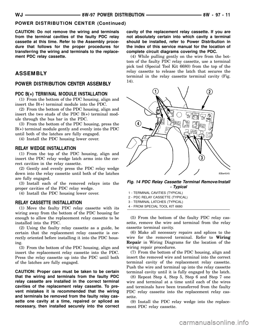
(4) While pulling gently on the wire from the bot-
tom of the faulty PDC relay cassette, use a terminal
pick tool (Special Tool Kit 6680) from the top of the
relay cassette to release the latch that secures the
terminal in the relay cassette terminal cavity (Fig.
14).
(5) From the bottom of the faulty PDC relay cas-
sette, remove the wire and terminal from the relay
cassette terminal cavity.
(6) Make all necessary repairs and splices to the
wire for the removed terminal. Refer toWiring
Repairin Wiring Diagrams for the location of the
wiring repair procedures.
(7) From the bottom of the PDC housing, align and
insert the removed wire and terminal into the correct
terminal cavity of the replacement relay cassette.
Push the wire and terminal up into the relay cassette
terminal cavity until it is fully engaged by the latch.
(8) Repeat Step 4, Step 5, Step 6 and Step 7 one
wire and terminal at a time until each of the wires
and terminals have been transferred from the faulty
PDC relay cassette into the replacement relay cas-
sette.
(9) Install the PDC relay wedge into the replace-
ment PDC relay cassette.
Fig. 14 PDC Relay Cassette Terminal Remove/Install
- Typical
1 - TERMINAL CAVITIES (TYPICAL)
2 - PDC RELAY CASSETTE (TYPICAL)
3 - TERMINAL LATCHES (TYPICAL)
4 - FROM SPECIAL TOOL KIT 6680
WJ8W-97 POWER DISTRIBUTION 8W - 97 - 11
POWER DISTRIBUTION CENTER (Continued)
Page 1253 of 2199
FORM-IN-PLACE GASKET AND SEALER
APPLICATION
Assembling parts using a form-in-place gasket
requires care but it's easier then using precut gaskets.
MopartGasket Maker material should be applied
sparingly 1 mm (0.040 in.) diameter or less of sealant
to one gasket surface. Be certain the material sur-
rounds each mounting hole. Excess material can eas-
ily be wiped off. Components should be torqued in
place within 15 minutes. The use of a locating dowel
is recommended during assembly to prevent smear-
ing material off the location.
MopartEngine RTV GEN II or ATF RTV gasket
material should be applied in a continuous bead
approximately 3 mm (0.120 in.) in diameter. All
mounting holes must be circled. For corner sealing, a
3.17 or 6.35 mm (1/8 or 1/4 in.) drop is placed in the
center of the gasket contact area. Uncured sealant
may be removed with a shop towel. Components
should be torqued in place while the sealant is still
wet to the touch (within 10 minutes). The usage of a
locating dowel is recommended during assembly to
prevent smearing material off the location.
MopartGasket Sealant in an aerosol can should be
applied using a thin, even coat sprayed completely
over both surfaces to be joined, and both sides of a
gasket. Then proceed with assembly. Material in a
can w/applicator can be brushed on evenly over the
sealing surfaces. Material in an aerosol can should be
used on engines with multi-layer steel gaskets.
STANDARD PROCEDURE - REPAIR DAMAGED
OR WORN THREADS
CAUTION: Be sure that the tapped holes maintain
the original center line.
Damaged or worn threads can be repaired. Essen-
tially, this repair consists of:
²Drilling out worn or damaged threads.
²Tapping the hole with a special Heli-Coil Tap, or
equivalent.
²Installing an insert into the tapped hole to bring
the hole back to its original thread size.
STANDARD PROCEDUREÐHYDROSTATIC LOCK
CAUTION: DO NOT use the starter motor to rotate
the crankshaft. Severe damage could occur.
When an engine is suspected of hydrostatic lock
(regardless of what caused the problem), follow the
steps below.
(1) Perform the Fuel Pressure Release Procedure
(Refer to 14 - FUEL SYSTEM/FUEL DELIVERY -
STANDARD PROCEDURE).(2) Disconnect the negative cable(s) from the bat-
tery.
(3) Inspect air cleaner, induction system, and
intake manifold to ensure system is dry and clear of
foreign material.
(4) Place a shop towel around the spark plugs to
catch any fluid that may possibly be under pressure
in the cylinder head. Remove the spark plugs.
(5) With all spark plugs removed, rotate the crank-
shaft using a breaker bar and socket.
(6) Identify the fluid in the cylinders (coolant, fuel,
oil, etc.).
(7) Be sure all fluid has been removed from the
cylinders.
(8) Repair engine or components as necessary to
prevent this problem from occurring again.
(9) Squirt a small amount of engine oil into the
cylinders to lubricate the walls. This will prevent
damage on restart.
(10) Install new spark plugs. Tighten the spark
plugs to 41 N´m (30 ft. lbs.) torque.
(11) Drain engine oil. Remove and discard the oil
filter.
(12) Install the drain plug. Tighten the plug to 34
N´m (25 ft. lbs.) torque.
(13) Install a new oil filter.
(14) Fill engine crankcase with the specified
amount and grade of oil. (Refer to LUBRICATION &
MAINTENANCE - SPECIFICATIONS).
(15) Connect the negative cable(s) to the battery.
(16) Start the engine and check for any leaks.
STANDARD PROCEDURE - CYLINDER BORE
HONING
Before honing, stuff plenty of clean shop towels
under the bores and over the crankshaft to keep
abrasive materials from entering the crankshaft
area.
(1)
Used carefully, the Cylinder Bore Sizing Hone
C-823, equipped with 220 grit stones, is the best tool
for this job. In addition to deglazing, it will reduce
taper and out-of-round, as well as removing light scuff-
ing, scoring and scratches. Usually, a few strokes will
clean up a bore and maintain the required limits.
CAUTION: DO NOT use rigid type hones to remove
cylinder wall glaze.
(2) Deglazing of the cylinder walls may be done if
the cylinder bore is straight and round. Use a cylin-
der surfacing hone, Honing Tool C-3501, equipped
with 280 grit stones (C-3501-3810). about 20-60
strokes, depending on the bore condition, will be suf-
ficient to provide a satisfactory surface. Using honing
oil C-3501-3880, or a light honing oil, available from
major oil distributors.
9 - 10 ENGINE - 4.0LWJ
ENGINE - 4.0L (Continued)
Page 1639 of 2199
INSPECTION
Replace the clutch discs if warped, worn, scored,
burned/charred, the lugs are damaged, or if the fac-
ing is flaking off. Replace the top and bottom pres-
sure plates if scored, warped, or cracked. Be sure the
driving lugs on the pressure and clutch plates are
also in good condition. The lugs must not be bent,
cracked or damaged in any way.
Replace the piston spring and wave spring if either
part is distorted, warped or broken.
Check the lug grooves in the clutch retainer. The
clutch and pressure plates should slide freely in the
slots. Replace the retainer if the grooves are worn or
damaged. Also check action of the check balls in the
retainer and piston. Each check ball must move
freely and not stick.
Replace the retainer bushing if worn, scored, or
doubt exists about bushing condition.
Inspect the piston and retainer seal surfaces for
nicks or scratches. Minor scratches can be removed
with crocus cloth. However, replace the piston and/or
retainer if the seal surfaces are seriously scored.
Check condition of the fiber thrust washer and
metal output shaft thrust washer. Replace either
washer if worn or damaged.
Check condition of the seal rings on the input shaft
and clutch retainer hub. Replace the seal rings only
if worn, distorted, or damaged. The input shaft front
seal ring is teflon with chamfered ends. The rear ring
is metal with interlocking ends.
Check the input shaft for wear, or damage. Replace
the shaft if worn, scored or damaged in any way.
ASSEMBLY
(1) Soak clutch discs in transmission fluid while
assembling other clutch parts.
(2) Install new seal rings on clutch retainer hub
and input shaft, if necessary, (Fig. 227) and (Fig.
228).
(a) Be sure clutch hub seal ring is fully seated in
groove and is not twisted.
(3) Lubricate splined end of input shaft and clutch
retainer with transmission fluid. Then press input
shaft into retainer (Fig. 229). Use a suitably sized
press tool to support retainer as close to input shaft
as possible.
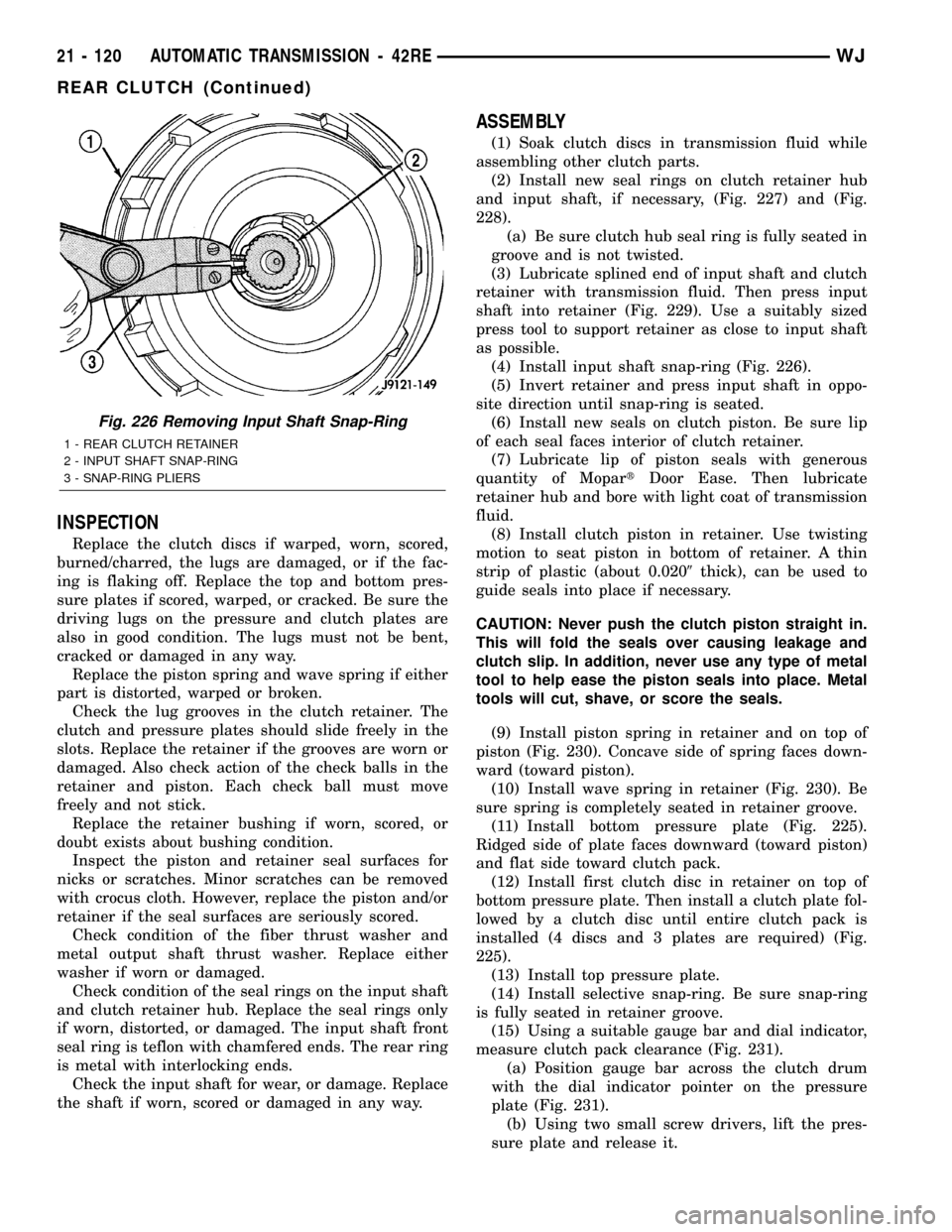
(4) Install input shaft snap-ring (Fig. 226).
(5) Invert retainer and press input shaft in oppo-
site direction until snap-ring is seated.
(6) Install new seals on clutch piston. Be sure lip
of each seal faces interior of clutch retainer.
(7) Lubricate lip of piston seals with generous
quantity of MopartDoor Ease. Then lubricate
retainer hub and bore with light coat of transmission
fluid.
(8) Install clutch piston in retainer. Use twisting
motion to seat piston in bottom of retainer. A thin
strip of plastic (about 0.0209thick), can be used to
guide seals into place if necessary.
CAUTION: Never push the clutch piston straight in.
This will fold the seals over causing leakage and
clutch slip. In addition, never use any type of metal
tool to help ease the piston seals into place. Metal
tools will cut, shave, or score the seals.
(9) Install piston spring in retainer and on top of
piston (Fig. 230). Concave side of spring faces down-
ward (toward piston).
(10) Install wave spring in retainer (Fig. 230). Be
sure spring is completely seated in retainer groove.
(11) Install bottom pressure plate (Fig. 225).
Ridged side of plate faces downward (toward piston)
and flat side toward clutch pack.
(12) Install first clutch disc in retainer on top of
bottom pressure plate. Then install a clutch plate fol-
lowed by a clutch disc until entire clutch pack is
installed (4 discs and 3 plates are required) (Fig.
225).
(13) Install top pressure plate.
(14) Install selective snap-ring. Be sure snap-ring
is fully seated in retainer groove.
(15) Using a suitable gauge bar and dial indicator,
measure clutch pack clearance (Fig. 231).
(a) Position gauge bar across the clutch drum
with the dial indicator pointer on the pressure
plate (Fig. 231).
(b) Using two small screw drivers, lift the pres-
sure plate and release it.
Fig. 226 Removing Input Shaft Snap-Ring
1 - REAR CLUTCH RETAINER
2 - INPUT SHAFT SNAP-RING
3 - SNAP-RING PLIERS
21 - 120 AUTOMATIC TRANSMISSION - 42REWJ
REAR CLUTCH (Continued)
Page 1829 of 2199
FLUID
STANDARD PROCEDURE - FLUID DRAIN/
REFILL
The fill and drain plugs are both in the rear case
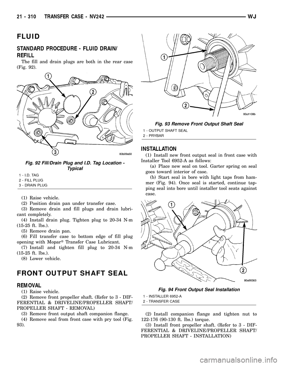
(Fig. 92).
(1) Raise vehicle.
(2) Position drain pan under transfer case.
(3) Remove drain and fill plugs and drain lubri-
cant completely.
(4) Install drain plug. Tighten plug to 20-34 N´m
(15-25 ft. lbs.).
(5) Remove drain pan.
(6) Fill transfer case to bottom edge of fill plug
opening with MopartTransfer Case Lubricant.
(7) Install and tighten fill plug to 20-34 N´m
(15-25 ft. lbs.).
(8) Lower vehicle.
FRONT OUTPUT SHAFT SEAL
REMOVAL
(1) Raise vehicle.
(2) Remove front propeller shaft. (Refer to 3 - DIF-
FERENTIAL & DRIVELINE/PROPELLER SHAFT/
PROPELLER SHAFT - REMOVAL)
(3) Remove front output shaft companion flange.
(4) Remove seal from front case with pry tool (Fig.
93).
INSTALLATION
(1) Install new front output seal in front case with
Installer Tool 6952-A as follows:
(a) Place new seal on tool. Garter spring on seal
goes toward interior of case.
(b) Start seal in bore with light taps from ham-
mer (Fig. 94). Once seal is started, continue tap-
ping seal into bore until installer tool seats against
case.
(2) Install companion flange and tighten nut to
122-176 (90-130 ft. lbs.) torque.
(3) Install front propeller shaft. (Refer to 3 - DIF-
FERENTIAL & DRIVELINE/PROPELLER SHAFT/
PROPELLER SHAFT - INSTALLATION)
Fig. 92 Fill/Drain Plug and I.D. Tag Location -
Typical
1 - I.D. TAG
2 - FILL PLUG
3 - DRAIN PLUG
Fig. 93 Remove Front Output Shaft Seal
1 - OUTPUT SHAFT SEAL
2 - PRYBAR
Fig. 94 Front Output Seal Installation
1 - INSTALLER 6952-A
2 - TRANSFER CASE
21 - 310 TRANSFER CASE - NV242WJ