Differential JEEP GRAND CHEROKEE 2003 WJ / 2.G Owner's Manual
[x] Cancel search | Manufacturer: JEEP, Model Year: 2003, Model line: GRAND CHEROKEE, Model: JEEP GRAND CHEROKEE 2003 WJ / 2.GPages: 2199, PDF Size: 76.01 MB
Page 84 of 2199
(6) Install propeller shaft with installation refer-
ence marks aligned.
(7) Fill differential with gear lubricant.
(8) Install brake rotors and calipers.
(9) Install wheel and tire assemblies.
(10) Lower the vehicle.
COLLAPSIBLE SPACER
REMOVAL
(1) Raise and support the vehicle.
(2) Remove wheel and tire assemblies.
(3) Remove brake rotors and calipers. Refer to 5
Brakes for procedures.
(4) Mark the propeller shaft and pinion companion
flange for installation reference.
(5) Remove propeller shaft from the pinion com-
panion flange.
(6) Rotate pinion gear a minimum of ten times and
verify pinion rotates smoothly.
(7) Record pinion gear rotating torque with a
torque wrench for installation reference.
(8) Remove pinion nut and washer. Using a short
piece of pipe and Spanner Wrench 6958 to hold the
pinion companion flange.
(9) Remove pinion companion flange with Remover
C-452 and Flange Wrench C-3281.
(10) Remove pinion shaft seal with Remover
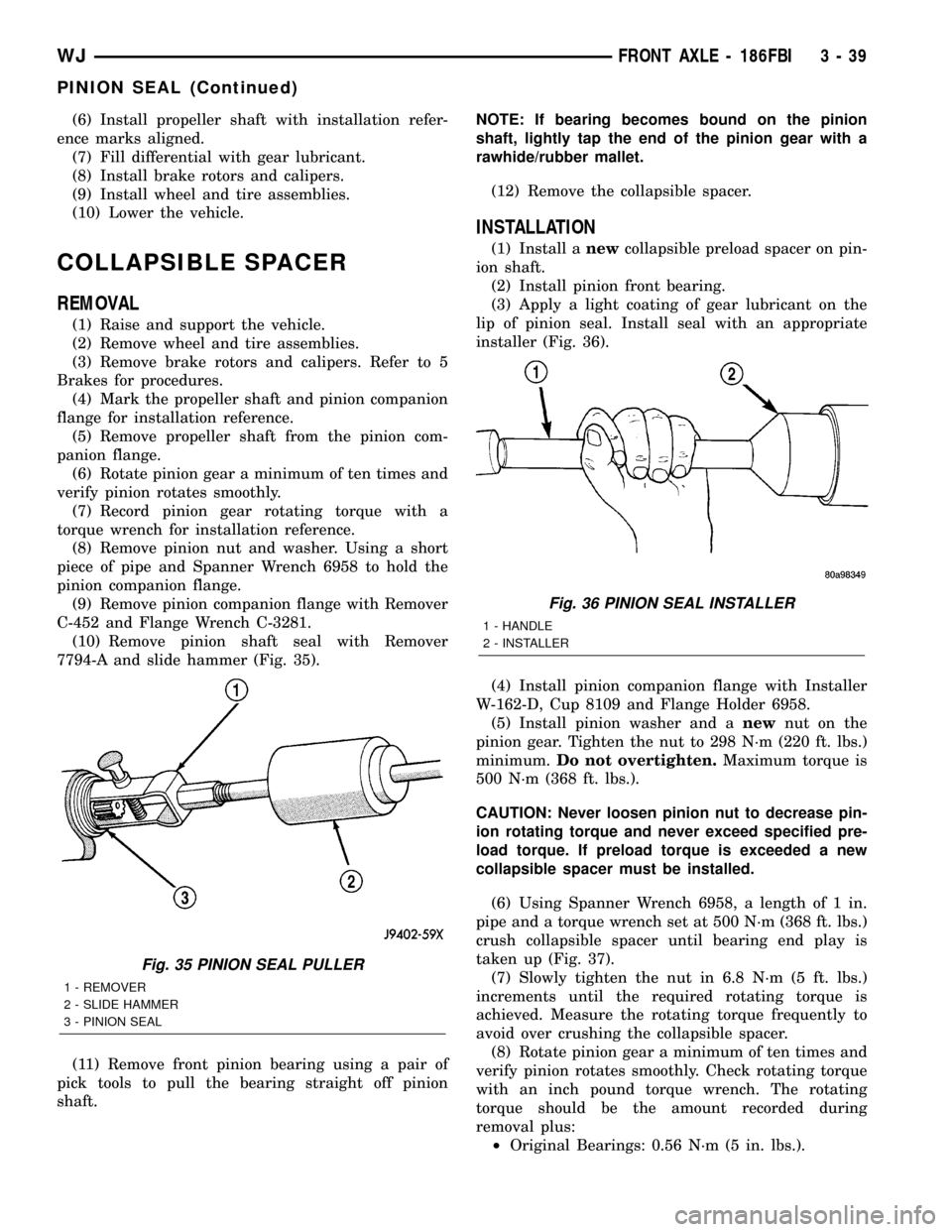
7794-A and slide hammer (Fig. 35).
(11) Remove front pinion bearing using a pair of
pick tools to pull the bearing straight off pinion
shaft.NOTE: If bearing becomes bound on the pinion
shaft, lightly tap the end of the pinion gear with a
rawhide/rubber mallet.
(12) Remove the collapsible spacer.
INSTALLATION
(1) Install anewcollapsible preload spacer on pin-
ion shaft.
(2) Install pinion front bearing.
(3) Apply a light coating of gear lubricant on the
lip of pinion seal. Install seal with an appropriate
installer (Fig. 36).
(4) Install pinion companion flange with Installer
W-162-D, Cup 8109 and Flange Holder 6958.
(5) Install pinion washer and anewnut on the
pinion gear. Tighten the nut to 298 N´m (220 ft. lbs.)
minimum.Do not overtighten.Maximum torque is
500 N´m (368 ft. lbs.).
CAUTION: Never loosen pinion nut to decrease pin-
ion rotating torque and never exceed specified pre-
load torque. If preload torque is exceeded a new
collapsible spacer must be installed.
(6) Using Spanner Wrench 6958, a length of 1 in.
pipe and a torque wrench set at 500 N´m (368 ft. lbs.)
crush collapsible spacer until bearing end play is
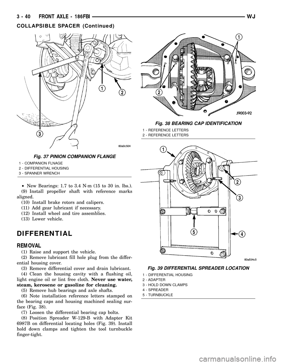
taken up (Fig. 37).
(7) Slowly tighten the nut in 6.8 N´m (5 ft. lbs.)
increments until the required rotating torque is
achieved. Measure the rotating torque frequently to
avoid over crushing the collapsible spacer.
(8) Rotate pinion gear a minimum of ten times and
verify pinion rotates smoothly. Check rotating torque
with an inch pound torque wrench. The rotating
torque should be the amount recorded during
removal plus:
²Original Bearings: 0.56 N´m (5 in. lbs.).
Fig. 35 PINION SEAL PULLER
1 - REMOVER
2 - SLIDE HAMMER
3 - PINION SEAL
Fig. 36 PINION SEAL INSTALLER
1 - HANDLE
2 - INSTALLER
WJFRONT AXLE - 186FBI 3 - 39
PINION SEAL (Continued)
Page 85 of 2199
²New Bearings: 1.7 to 3.4 N´m (15 to 30 in. lbs.).
(9) Install propeller shaft with reference marks
aligned.
(10) Install brake rotors and calipers.
(11) Add gear lubricant if necessary.
(12) Install wheel and tire assemblies.
(13) Lower vehicle.
DIFFERENTIAL
REMOVAL
(1) Raise and support the vehicle.
(2) Remove lubricant fill hole plug from the differ-
ential housing cover.
(3) Remove differential cover and drain lubricant.
(4) Clean the housing cavity with a flushing oil,
light engine oil or lint free cloth.Never use water,
steam, kerosene or gasoline for cleaning.
(5) Remove hub bearings and axle shafts.
(6) Note installation reference letters stamped on
the bearing caps and housing machined sealing sur-
face (Fig. 38).
(7) Loosen the differential bearing cap bolts.
(8) Position Spreader W-129-B with Adapter Kit
6987B on differential locating holes (Fig. 39). Install
hold down clamps and tighten the tool turnbuckle
finger-tight.
Fig. 37 PINION COMPANION FLANGE
1 - COMPANION FLNAGE
2 - DIFFERENTIAL HOUSING
3 - SPANNER WRENCH
Fig. 38 BEARING CAP IDENTIFICATION
1 - REFERENCE LETTERS
2 - REFERENCE LETTERS
Fig. 39 DIFFERENTIAL SPREADER LOCATION
1 - DIFFERENTIAL HOUSING
2 - ADAPTER
3 - HOLD DOWN CLAMPS
4 - SPREADER
5 - TURNBUCKLE
3 - 40 FRONT AXLE - 186FBIWJ
COLLAPSIBLE SPACER (Continued)
Page 86 of 2199
(9) Install a Pilot Stud C-3288-B at the left side of
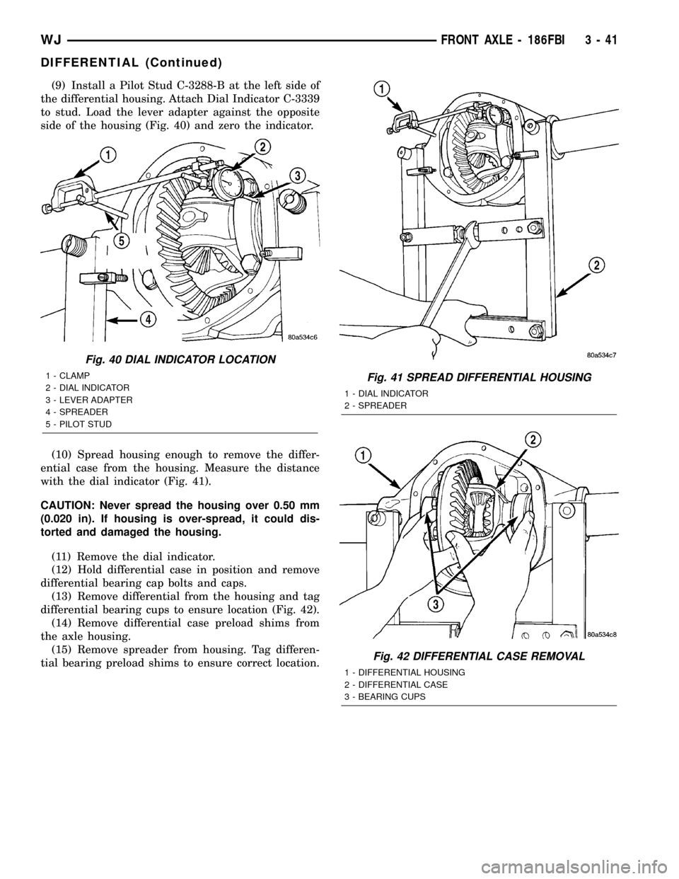
the differential housing. Attach Dial Indicator C-3339
to stud. Load the lever adapter against the opposite
side of the housing (Fig. 40) and zero the indicator.
(10) Spread housing enough to remove the differ-
ential case from the housing. Measure the distance
with the dial indicator (Fig. 41).
CAUTION: Never spread the housing over 0.50 mm
(0.020 in). If housing is over-spread, it could dis-
torted and damaged the housing.
(11) Remove the dial indicator.
(12) Hold differential case in position and remove
differential bearing cap bolts and caps.
(13) Remove differential from the housing and tag
differential bearing cups to ensure location (Fig. 42).
(14) Remove differential case preload shims from
the axle housing.
(15) Remove spreader from housing. Tag differen-
tial bearing preload shims to ensure correct location.
Fig. 40 DIAL INDICATOR LOCATION
1 - CLAMP
2 - DIAL INDICATOR
3 - LEVER ADAPTER
4 - SPREADER
5 - PILOT STUDFig. 41 SPREAD DIFFERENTIAL HOUSING
1 - DIAL INDICATOR
2 - SPREADER
Fig. 42 DIFFERENTIAL CASE REMOVAL
1 - DIFFERENTIAL HOUSING
2 - DIFFERENTIAL CASE
3 - BEARING CUPS
WJFRONT AXLE - 186FBI 3 - 41
DIFFERENTIAL (Continued)
Page 87 of 2199
DISASSEMBLY
(1) Remove the ring gear.
(2) Drive out the roll pin holding pinion gear mate
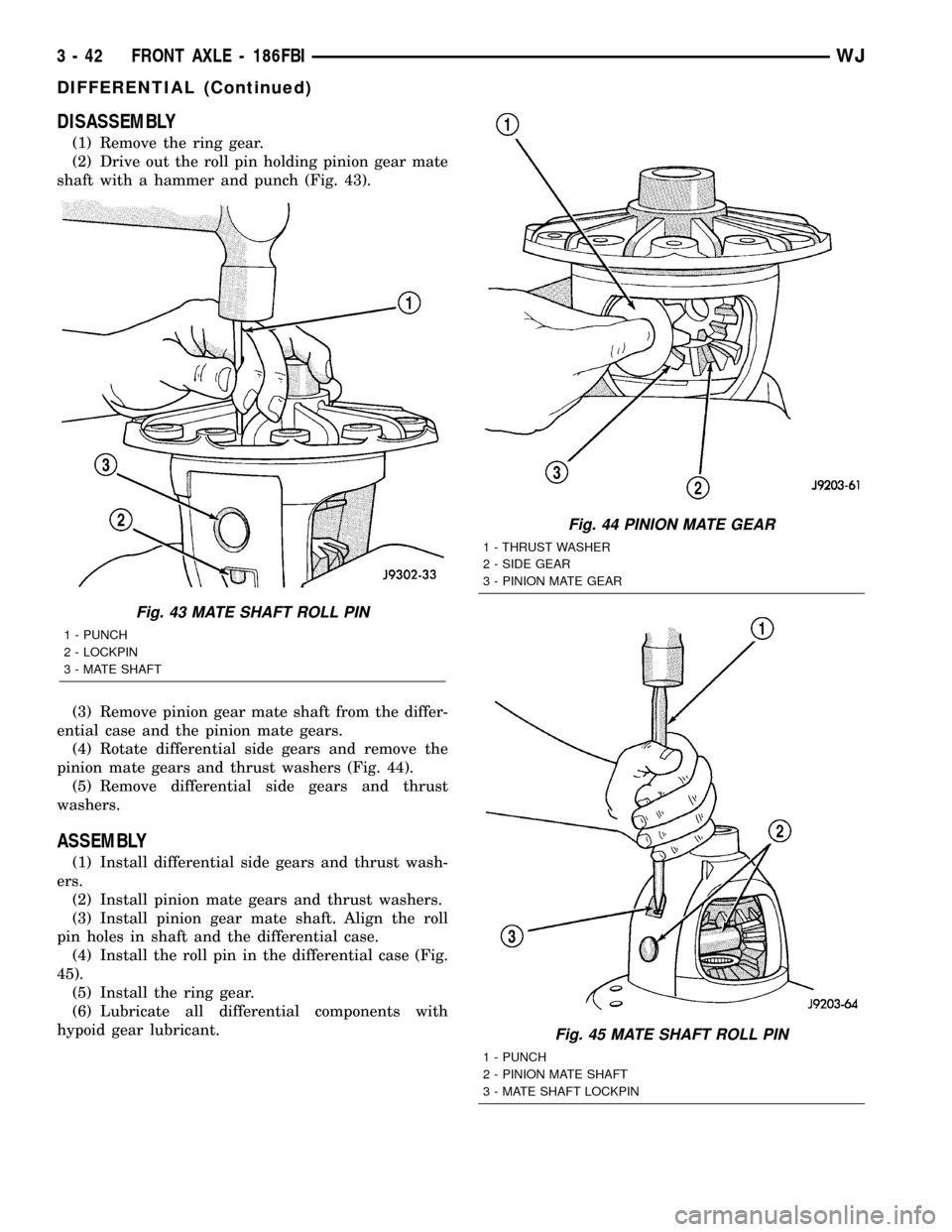
shaft with a hammer and punch (Fig. 43).
(3) Remove pinion gear mate shaft from the differ-
ential case and the pinion mate gears.
(4) Rotate differential side gears and remove the
pinion mate gears and thrust washers (Fig. 44).
(5) Remove differential side gears and thrust
washers.
ASSEMBLY
(1) Install differential side gears and thrust wash-
ers.
(2) Install pinion mate gears and thrust washers.
(3) Install pinion gear mate shaft. Align the roll
pin holes in shaft and the differential case.
(4) Install the roll pin in the differential case (Fig.
45).
(5) Install the ring gear.
(6) Lubricate all differential components with
hypoid gear lubricant.
Fig. 43 MATE SHAFT ROLL PIN
1 - PUNCH
2 - LOCKPIN
3 - MATE SHAFT
Fig. 44 PINION MATE GEAR
1 - THRUST WASHER
2 - SIDE GEAR
3 - PINION MATE GEAR
Fig. 45 MATE SHAFT ROLL PIN
1 - PUNCH
2 - PINION MATE SHAFT
3 - MATE SHAFT LOCKPIN
3 - 42 FRONT AXLE - 186FBIWJ
DIFFERENTIAL (Continued)
Page 88 of 2199
INSTALLATION
NOTE: If replacement differential bearings or differ-
ential case are being installed, differential side
bearing shim requirements may change. Refer to
Adjustments (Differential Bearing Preload and Gear
Backlash) to determine the proper shim selection.
(1) Position Spreader W-129-B with Adapter Kit
6987B on differential locating holes. Install hold
down clamps and tighten the tool turnbuckle finger-
tight.
(2) Install a Pilot Stud C-3288-B at the left side of
the differential housing. Attach Dial Indicator C-3339
to pilot stud. Load the indicator plunger against the
opposite side of the housing and zero the indicator.
(3) Spread the housing enough to install the case
in the housing. Measure the distance with the dial
indicator.
CAUTION: Never spread the housing over 0.50 mm
(0.020 in). If housing is over-spread, it could dis-
torted and damaged the housing.
(4) Remove the dial indicator.
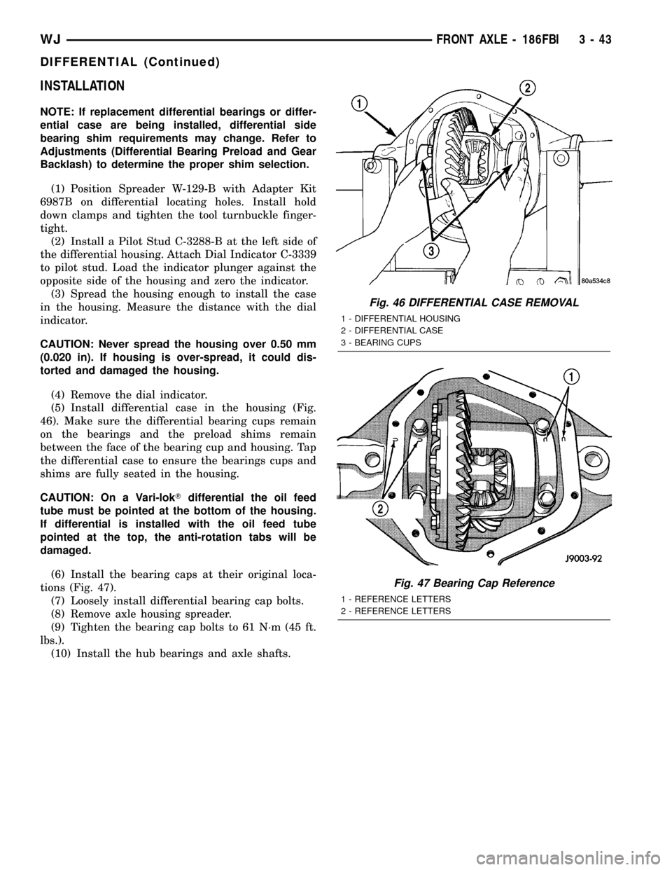
(5) Install differential case in the housing (Fig.
46). Make sure the differential bearing cups remain
on the bearings and the preload shims remain
between the face of the bearing cup and housing. Tap
the differential case to ensure the bearings cups and
shims are fully seated in the housing.
CAUTION: On a Vari-lokTdifferential the oil feed
tube must be pointed at the bottom of the housing.
If differential is installed with the oil feed tube
pointed at the top, the anti-rotation tabs will be
damaged.
(6) Install the bearing caps at their original loca-
tions (Fig. 47).
(7) Loosely install differential bearing cap bolts.
(8) Remove axle housing spreader.
(9) Tighten the bearing cap bolts to 61 N´m (45 ft.
lbs.).
(10) Install the hub bearings and axle shafts.
Fig. 46 DIFFERENTIAL CASE REMOVAL
1 - DIFFERENTIAL HOUSING
2 - DIFFERENTIAL CASE
3 - BEARING CUPS
Fig. 47 Bearing Cap Reference
1 - REFERENCE LETTERS
2 - REFERENCE LETTERS
WJFRONT AXLE - 186FBI 3 - 43
DIFFERENTIAL (Continued)
Page 89 of 2199
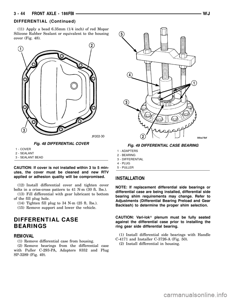
(11) Apply a bead 6.35mm (1/4 inch) of red Mopar
Silicone Rubber Sealant or equivalent to the housing
cover (Fig. 48).
CAUTION: If cover is not installed within 3 to 5 min-
utes, the cover must be cleaned and new RTV
applied or adhesion quality will be compromised.
(12) Install differential cover and tighten cover
bolts in a criss-cross pattern to 41 N´m (30 ft. lbs.).
(13) Fill differential with gear lubricant to bottom
of the fill plug hole.
(14) Tighten fill plug to 34 N´m (25 ft. lbs.).
(15) Remove support and lower the vehicle.
DIFFERENTIAL CASE
BEARINGS
REMOVAL
(1) Remove differential case from housing.
(2) Remove bearings from the differential case
with Puller C-293-PA, Adapters 8352 and Plug
SP-3289 (Fig. 49).
INSTALLATION
NOTE: If replacement differential side bearings or
differential case are being installed, differential side
bearing shim requirements may change. Refer to
Adjustments (Differential Bearing Preload and Gear
Backlash) to determine the proper shim selection.
CAUTION: Vari-lokTplenum must be fully seated
against the differential case prior to installing the
ring gear side differential bearing.
(1) Install differential side bearings with Handle
C-4171 and Installer C-3726-A (Fig. 50).
(2) Install differential in housing.
Fig. 48 DIFFERENTIAL COVER
1 - COVER
2 - SEALANT
3 - SEALANT BEADFig. 49 DIFFERENTIAL CASE BEARING
1 - ADAPTERS
2 - BEARING
3 - DIFFERENTIAL
4 - PLUG
5 - PULLER
3 - 44 FRONT AXLE - 186FBIWJ
DIFFERENTIAL (Continued)
Page 90 of 2199
PINION GEAR/RING GEAR
REMOVAL
NOTE: The ring gear and pinion are serviced as a
matched set. Nevar replace one gear without replac-
ing the other matching gear.
(1) Raise and support vehicle
(2) Mark pinion companion flange and propeller
shaft for installation alignment.
(3) Remove propeller shaft from pinion companion
flange and tie propeller shaft to underbody.
(4) Remove differential from axle housing.
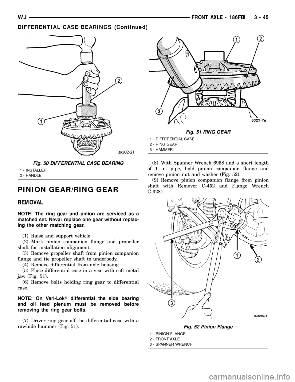
(5) Place differential case in a vise with soft metal
jaw (Fig. 51).
(6) Remove bolts holding ring gear to differential
case.
NOTE: On Veri-LokTdifferential the side bearing
and oil feed plenum must be removed before
removing the ring gear bolts.
(7) Driver ring gear off the differential case with a
rawhide hammer (Fig. 51).(8) With Spanner Wrench 6958 and a short length
of 1 in. pipe, hold pinion companion flange and
remove pinion nut and washer (Fig. 52).
(9) Remove pinion companion flange from pinion
shaft with Remover C-452 and Flange Wrench
C-3281.
Fig. 50 DIFFERENTIAL CASE BEARING
1 - INSTALLER
2 - HANDLE
Fig. 51 RING GEAR
1 - DIFFERENTIAL CASE
2 - RING GEAR
3 - HAMMER
Fig. 52 Pinion Flange
1 - PINION FLANGE
2 - FRONT AXLE
3 - SPANNER WRENCH
WJFRONT AXLE - 186FBI 3 - 45
DIFFERENTIAL CASE BEARINGS (Continued)
Page 93 of 2199
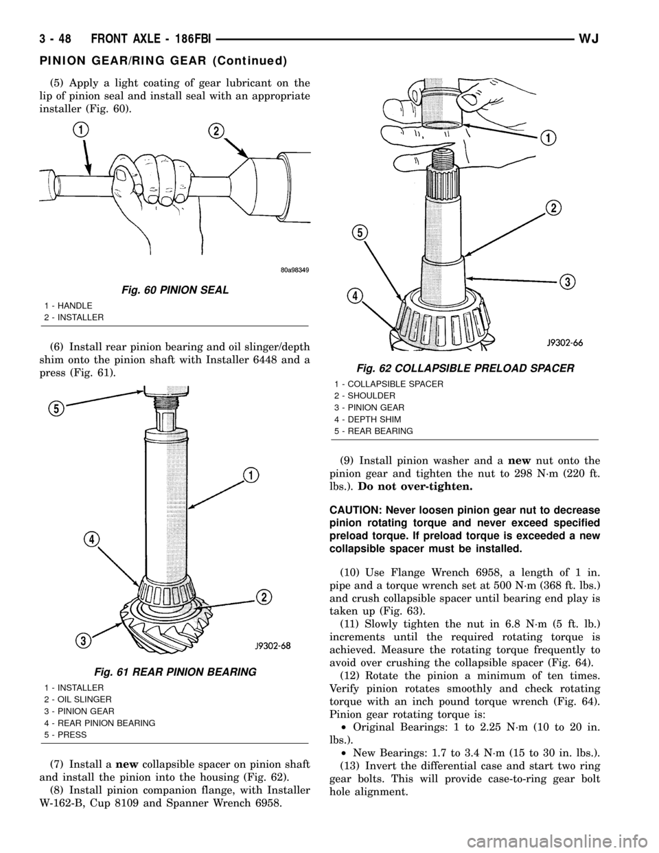
(5) Apply a light coating of gear lubricant on the
lip of pinion seal and install seal with an appropriate
installer (Fig. 60).
(6) Install rear pinion bearing and oil slinger/depth
shim onto the pinion shaft with Installer 6448 and a
press (Fig. 61).
(7) Install anewcollapsible spacer on pinion shaft
and install the pinion into the housing (Fig. 62).
(8) Install pinion companion flange, with Installer
W-162-B, Cup 8109 and Spanner Wrench 6958.(9) Install pinion washer and anewnut onto the
pinion gear and tighten the nut to 298 N´m (220 ft.
lbs.).Do not over-tighten.
CAUTION: Never loosen pinion gear nut to decrease
pinion rotating torque and never exceed specified
preload torque. If preload torque is exceeded a new
collapsible spacer must be installed.
(10) Use Flange Wrench 6958, a length of 1 in.
pipe and a torque wrench set at 500 N´m (368 ft. lbs.)
and crush collapsible spacer until bearing end play is
taken up (Fig. 63).
(11) Slowly tighten the nut in 6.8 N´m (5 ft. lb.)
increments until the required rotating torque is
achieved. Measure the rotating torque frequently to
avoid over crushing the collapsible spacer (Fig. 64).
(12) Rotate the pinion a minimum of ten times.
Verify pinion rotates smoothly and check rotating
torque with an inch pound torque wrench (Fig. 64).
Pinion gear rotating torque is:
²Original Bearings: 1 to 2.25 N´m (10 to 20 in.
lbs.).
²New Bearings: 1.7 to 3.4 N´m (15 to 30 in. lbs.).
(13) Invert the differential case and start two ring
gear bolts. This will provide case-to-ring gear bolt
hole alignment.
Fig. 60 PINION SEAL
1 - HANDLE
2 - INSTALLER
Fig. 61 REAR PINION BEARING
1 - INSTALLER
2 - OIL SLINGER
3 - PINION GEAR
4 - REAR PINION BEARING
5 - PRESS
Fig. 62 COLLAPSIBLE PRELOAD SPACER
1 - COLLAPSIBLE SPACER
2 - SHOULDER
3 - PINION GEAR
4 - DEPTH SHIM
5 - REAR BEARING
3 - 48 FRONT AXLE - 186FBIWJ
PINION GEAR/RING GEAR (Continued)
Page 94 of 2199
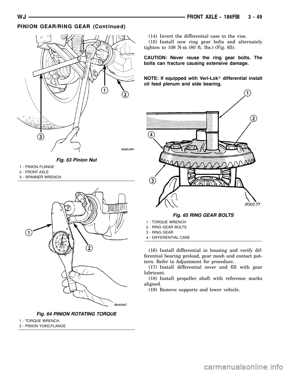
(14) Invert the differential case in the vise.
(15) Install new ring gear bolts and alternately
tighten to 108 N´m (80 ft. lbs.) (Fig. 65).
CAUTION: Never reuse the ring gear bolts. The
bolts can fracture causing extensive damage.
NOTE: If equipped with Veri-LokTdifferential install
oil feed plenum and side bearing.
(16) Install differential in housing and verify dif-
ferential bearing preload, gear mesh and contact pat-
tern. Refer to Adjustment for procedure.
(17) Install differential cover and fill with gear
lubricant.
(18) Install propeller shaft with reference marks
aligned.
(19) Remove supports and lower vehicle.
Fig. 63 Pinion Nut
1 - PINION FLANGE
2 - FRONT AXLE
3 - SPANNER WRENCH
Fig. 64 PINION ROTATING TORQUE
1 - TORQUE WRENCH
2 - PINION YOKE/FLANGE
Fig. 65 RING GEAR BOLTS
1 - TORQUE WRENCH
2 - RING GEAR BOLTS
3 - RING GEAR
4 - DIFFERENTIAL CASE
WJFRONT AXLE - 186FBI 3 - 49
PINION GEAR/RING GEAR (Continued)
Page 95 of 2199
REAR AXLE - 198RBI
TABLE OF CONTENTS
page page
REAR AXLE - 198RBI
DESCRIPTION.........................50
OPERATION...........................50
DIAGNOSIS AND TESTING................51
REMOVAL.............................55
INSTALLATION.........................56
ADJUSTMENTS........................56
SPECIFICATIONS.......................65
SPECIAL TOOLS.......................66
AXLE SHAFTS
REMOVAL.............................69
INSTALLATION.........................69
AXLE BEARINGS/SEALS
REMOVAL.............................69
INSTALLATION.........................70
PINION SEAL
REMOVAL.............................71
INSTALLATION.........................71
COLLAPSIBLE SPACER
REMOVAL.............................73INSTALLATION.........................73
DIFFERENTIAL
REMOVAL.............................75
DISASSEMBLY.........................77
ASSEMBLY............................77
INSTALLATION.........................77
DIFFERENTIAL-TRAC-LOC
DIAGNOSIS AND TESTING................79
DISASSEMBLY.........................79
CLEANING............................82
INSPECTION..........................82
ASSEMBLY............................82
DIFFERENTIAL CASE BEARINGS
REMOVAL.............................83
INSTALLATION.........................84
PINION GEAR/RING GEAR
REMOVAL.............................84
INSTALLATION.........................86
REAR AXLE - 198RBI
DESCRIPTION
The Rear Beam-design Iron (RBI) axle housing has
an iron center casting with axle shaft tubes extend-
ing from either side. The tubes are pressed into and
welded to the differential housing to form a one-piece
axle housing. The axles has semi-floating axle shafts,
meaning that loads are supported by the axle shaft
and bearings. The axle shafts are retained by bearing
retainer plates on the axles which are bolted to
flanges at the outboard end of the axle tubes.
The differential case is a one-piece design. Differ-
ential bearing preload and ring gear backlash is
adjusted by the use of selective spacer shims. Pinion
bearing preload is set and maintained by the use of a
collapsible spacer. A differential cover provides a
means for inspection and service.
Axles with optional Trac-Loktdifferential have a
one-piece differential case, and the same internal
components as a standard differential, plus two
clutch disc packs.
OPERATION
The axle receives power from the transmission/
transfer case through the rear propeller shaft. Therear propeller shaft is connected to the pinion gear
which rotates the differential through the gear mesh
with the ring gear bolted to the differential case. The
engine power is transmitted to the axle shafts
through the pinion mate and side gears. The side
gears are splined to the axle shafts.
STANDARD DIFFERENTIAL
During straight-ahead driving, the differential pin-
ion gears do not rotate on the pinion mate shaft. This
occurs because input torque applied to the gears is
divided and distributed equally between the two side
gears. As a result, the pinion gears revolve with the
pinion mate shaft but do not rotate around it (Fig. 1).
When turning corners, the outside wheel must
travel a greater distance than the inside wheel to
complete a turn. The difference must be compensated
for to prevent the tires from scuffing and skidding
through turns. To accomplish this, the differential
allows the axle shafts to turn at unequal speeds (Fig.
2). In this instance, the input torque applied to the
pinion gears is not divided equally. The pinion gears
now rotate around the pinion mate shaft in opposite
directions. This allows the side gear and axle shaft
attached to the outside wheel to rotate at a faster
speed.
3 - 50 REAR AXLE - 198RBIWJ