Panel JEEP GRAND CHEROKEE 2003 WJ / 2.G Workshop Manual
[x] Cancel search | Manufacturer: JEEP, Model Year: 2003, Model line: GRAND CHEROKEE, Model: JEEP GRAND CHEROKEE 2003 WJ / 2.GPages: 2199, PDF Size: 76.01 MB
Page 1942 of 2199

INTERIOR
TABLE OF CONTENTS
page page
A-PILLAR TRIM
REMOVAL.............................69
INSTALLATION.........................69
ASSIST HANDLE
REMOVAL.............................70
INSTALLATION.........................70
B-PILLAR LOWER TRIM
REMOVAL.............................70
INSTALLATION.........................70
B-PILLAR UPPER TRIM
REMOVAL.............................71
INSTALLATION.........................71
CARPETS AND FLOOR MATS
REMOVAL
REMOVAL - FRONT CARPET............71
REMOVAL - CARGO AREA CARPET.......71
INSTALLATION
INSTALLATION - FRONT CARPET.........71
INSTALLATION - CARGO AREA CARPET . . . 72
COWL TRIM
REMOVAL.............................72
INSTALLATION.........................72
C-PILLAR TRIM
REMOVAL.............................72
INSTALLATION.........................72
DOOR SILL SCUFF PLATE
REMOVAL.............................74
INSTALLATION.........................74
DOOR SILL TRIM
REMOVAL.............................74INSTALLATION.........................74
D-PILLAR TRIM
REMOVAL.............................75
INSTALLATION.........................75
FLOOR CONSOLE
REMOVAL.............................76
INSTALLATION.........................76
HEADLINER
REMOVAL.............................77
INSTALLATION.........................77
LIFTGATE OPENING UPPER TRIM
REMOVAL.............................79
INSTALLATION.........................79
QUARTER TRIM PANEL
REMOVAL.............................79
INSTALLATION.........................79
REAR STORAGE BOX
REMOVAL.............................79
INSTALLATION.........................80
REAR VIEW MIRROR
REMOVAL.............................80
INSTALLATION
INSTALLATION.......................80
INSTALLATION - REARVIEW MIRROR
SUPPORT BRACKET...................80
SUN VISOR
REMOVAL.............................80
INSTALLATION.........................80
A-PILLAR TRIM
REMOVAL
The A-pillar trim is attached to the A-pillar with
spring clips.
(1) Grasp A-pillar trim and pull trim outward from
A-pillar (Fig. 1).
(2) Separate A-pillar trim from A-pillar.
INSTALLATION
(1) Position A-pillar trim on A-pillar and, starting
at the bottom, press into place (Fig. 1).
(2) Using a trim stick or other suitable tool, care-
fully cover the edge of the trim with weatherstrip.
Fig. 1 A-Pillar Trim
1 - A-PILLAR TRIM
2 - A-PILLAR
3 - SPRING CLIP
WJINTERIOR 23 - 69
Page 1943 of 2199

ASSIST HANDLE
REMOVAL
(1) Remove the screws holding the assist handle to
the roof panel.
(2) Remove the assist handle from the roof panel.
INSTALLATION
(1) Align the assist handle with the screw holes in
the roof panel.
(2) Install the screws holding the assist handle to
the roof panel.
B-PILLAR LOWER TRIM
REMOVAL
(1) Remove front door sill trim (Refer to 23 -
BODY/INTERIOR/DOOR SILL TRIM - REMOVAL).
(2) Remove front seat shoulder belt anchor bolt.(3) Remove front seat shoulder belt height adjust-
ment knob and turning loop.
(4) Remove screw attaching front of quarter panel
trim to floor.
(5) Remove screws attaching front and rear of
B-pillar lower trim to floor.
(6) Remove screw attaching B-pillar lower trim to
B-pillar (Fig. 2).
(7) Grasp B-pillar lower trim and pull outward to
separate from B-pillar.
(8) Route seat/shoulder belt through access slot in
B-pillar lower trim.
(9) Separate B-pillar lower trim from B-pillar.
INSTALLATION
(1) Position B-pillar lower trim panel at B-pillar
(Fig. 2).
(2) Route seat/shoulder belt through access slot in
B-pillar lower trim.
(3) Press B-pillar lower trim onto B-pillar.
Fig. 2 B-Pillar Trim Panel
1 - B-PILLAR UPPER TRIM
2 - ACCESS COVER
3 - B-PILLAR LOWER TRIM
4 - PLASTIC NUT
5 - COWL LOWER TRIM6 - CLIP
7 - SCUFF PLATE
8 - SILL TRIM
9 - A-PILLAR TRIM
23 - 70 INTERIORWJ
Page 1944 of 2199

(4) Install screw attaching B-pillar lower trim to
B-pillar.
(5) Install screw attaching front of B-pillar lower
trim to floor.
(6) Install screw attaching front of quarter panel
trim to floor.
(7) Install front seat shoulder belt anchor bolt.
(8) Install front seat shoulder belt height adjust-
ment knob and turning loop.
(9) Install front door sill trim (Refer to 23 - BODY/
INTERIOR/DOOR SILL TRIM - INSTALLATION).
B-PILLAR UPPER TRIM
REMOVAL
(1) Remove shoulder belt height adjustment knob.
(2) Remove front seat belt turning loop.
(3) Remove the screw attaching lower B pillar
trim.
(4) Pull lower B pillar trim out far enough to
remove upper trim panel.
(5) Grasp upper B-pillar trim and pull outward to
detach from B-pillar (Fig. 2).
INSTALLATION
(1) Position trim panel on B-pillar (Fig. 2).
(2) Ensure trim panel covers inner edge of door
opening weatherstrip and press inward to seat.
(3) Install screw attaching lower B pillar trim
panel.
(4) Install front seat belt turning loop.
(5) Install shoulder belt height adjustment knob.
CARPETS AND FLOOR MATS
REMOVAL
REMOVAL - FRONT CARPET
(1) Remove door sill trim (Refer to 23 - BODY/IN-
TERIOR/DOOR SILL TRIM - REMOVAL).
(2) Remove the B-pillar lower trim, refer to (Refer
to 23 - BODY/INTERIOR/B-PILLAR LOWER TRIM -
REMOVAL).
(3) Remove front seats (Refer to 23 - BODY/
SEATS/SEAT - REMOVAL).
(4) Remove the rear seats lower cushions (Refer to
23 - BODY/SEATS/SEAT CUSHION - REMOVAL).
(5) Remove center floor console (Refer to 23 -
BODY/INTERIOR/FLOOR CONSOLE - REMOVAL).
(6) Remove any other interfering trim or molding.
(7) Lift carpet and mat from floor panel.
REMOVAL - CARGO AREA CARPET
(1) Lift tailgate.
(2) Fold rear seat cushions forward.
(3) Remove rear seat backs (Refer to 23 - BODY/
SEATS/REAR SEAT BACK - REMOVAL).
(4) Remove the rear shoulder belts (Refer to 8 -
ELECTRICAL/RESTRAINTS/REAR SEAT BELT &
RETRACTOR - REMOVAL).
(5) Remove the retractable security cargo cover
assembly.
(6) Remove the spare tire cover.
(7) Remove the rear cargo tie down footman loops.
The side mounted footman loops are retained by
screws. The floor footman loops are riveted (Fig. 3).
(8) Remove the C pillar trim (Refer to 23 - BODY/
INTERIOR/C-PILLAR TRIM - REMOVAL).
(9) Remove the CD changer, if equipped (Refer to 8
- ELECTRICAL/AUDIO/CD CHANGER - REMOV-
AL).
(10) Remove the Infinity amp, if equipped (Refer to
8 - ELECTRICAL/AUDIO/AMPLIFIER - REMOVAL).
(11) Lift the carpet.
INSTALLATION
INSTALLATION - FRONT CARPET
(1) Carefully lay the carpet and mat on the floor
panel. Align the carpet to allow installation of the
components fastened to the floor panel.
(2) Install the center console (Refer to 23 - BODY/
INTERIOR/FLOOR CONSOLE - INSTALLATION).
(3) Install the front seats (Refer to 23 - BODY/
SEATS/SEAT - INSTALLATION).
(4) Install the rear seat cushions (Refer to 23 -
BODY/SEATS/SEAT CUSHION - INSTALLATION).
Fig. 3 Cargo Area Carpet
1 - CARGO AREA CARPET
2 - RIVET
3 - CARGO TIE-DOWN LOOP
WJINTERIOR 23 - 71
B-PILLAR LOWER TRIM (Continued)
Page 1945 of 2199

(5) Install the lower B pillar trim (Refer to 23 -
BODY/INTERIOR/B-PILLAR LOWER TRIM -
INSTALLATION).
(6) Install the door sill trim (Refer to 23 - BODY/
INTERIOR/DOOR SILL TRIM - INSTALLATION).
(7) Install any other moldings or trim panels
removed.
INSTALLATION - CARGO AREA CARPET
(1) Thoroughly clean the area with Mopar Super
Kleent, or equivalent.
(2) Lay the new carpet in.
(3) Install the ªCº pillar trim (Refer to 23 - BODY/
INTERIOR/C-PILLAR TRIM - INSTALLATION).
(4) Install the CD changer, if equipped (Refer to 8 -
ELECTRICAL/AUDIO/CD CHANGER - INSTALLA-
TION).
(5) Install the footman loops (Fig. 3).
(6) Install the rear shoulder belts (Refer to 8 -
ELECTRICAL/RESTRAINTS/REAR SEAT BELT &
RETRACTOR - INSTALLATION).
(7) Install the rear seat backs (Refer to 23 -
BODY/SEATS/REAR SEAT BACK - INSTALLA-
TION).
(8) Install the Infinity amp, if equipped (Refer to 8
- ELECTRICAL/AUDIO/AMPLIFIER - INSTALLA-
TION).
(9) Install the spare tire cover.
(10) Install the retractable security cover.
COWL TRIM
REMOVAL
(1) Remove front door sill trim (Refer to 23 -
BODY/INTERIOR/DOOR SILL TRIM - REMOVAL).
(2) Remove screws attaching cowl trim to floor.
(3) Remove plastic nut.
(4) Grasp cowl trim and pull outward to separate
from clip.
(5) Separate cowl trim from vehicle.
INSTALLATION
(1) Position cowl trim and press into place.
(2) Install screws attaching cowl trim to floor.
(3) Install plastic nut.
(4) Install front door sill trim (Refer to 23 - BODY/
INTERIOR/DOOR SILL TRIM - INSTALLATION).
C-PILLAR TRIM
REMOVAL
(1) Remove rear shoulder belt turning loop.
(2) Remove rear shoulder belt height adjustment
knob.
(3) Remove screws attaching quarter panel trim.
(4) Pull quarter panel trim outward as necessary.
(5) Grasp C-pillar upper trim and pull outward to
disengage from C-pillar (Fig. 4).
(6) Route rear shoulder belt through access hole.
(7) Separate C-pillar upper trim from vehicle.
INSTALLATION
(1) Position C-pillar upper trim at C-pillar (Fig. 4).
(2) Route rear shoulder belt through access hole.
(3) Press C-pillar upper trim onto C-pillar.
(4) Press quarter panel trim into place as neces-
sary.
(5) Ensure front edge of trim is covered by weath-
erstrip.
(6) Install screws attaching quarter panel trim.
(7) Install rear shoulder belt height adjustment
knob.
(8) Install rear shoulder belt turning loop.
23 - 72 INTERIORWJ
CARPETS AND FLOOR MATS (Continued)
Page 1946 of 2199
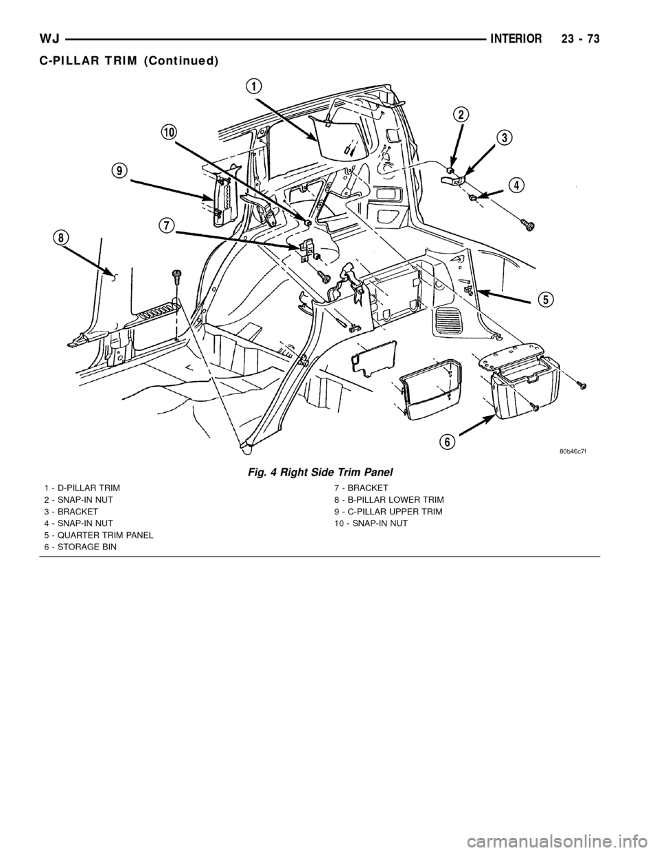
Fig. 4 Right Side Trim Panel
1 - D-PILLAR TRIM
2 - SNAP-IN NUT
3 - BRACKET
4 - SNAP-IN NUT
5 - QUARTER TRIM PANEL
6 - STORAGE BIN7 - BRACKET
8 - B-PILLAR LOWER TRIM
9 - C-PILLAR UPPER TRIM
10 - SNAP-IN NUT
WJINTERIOR 23 - 73
C-PILLAR TRIM (Continued)
Page 1948 of 2199
D-PILLAR TRIM
REMOVAL
The D-pillar trim is attached to the D-pillar with
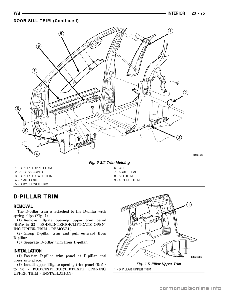
spring clips (Fig. 7).
(1) Remove liftgate opening upper trim panel
(Refer to 23 - BODY/INTERIOR/LIFTGATE OPEN-
ING UPPER TRIM - REMOVAL).
(2) Grasp D-pillar trim and pull outward from
D-pillar.
(3) Separate D-pillar trim from D-pillar.
INSTALLATION
(1) Position D-pillar trim panel at D-pillar and
press into place.
(2) Install upper liftgate opening trim panel (Refer
to 23 - BODY/INTERIOR/LIFTGATE OPENING
UPPER TRIM - INSTALLATION).
Fig. 6 Sill Trim Molding
1 - B-PILLAR UPPER TRIM
2 - ACCESS COVER
3 - B-PILLAR LOWER TRIM
4 - PLASTIC NUT
5 - COWL LOWER TRIM6 - CLIP
7 - SCUFF PLATE
8 - SILL TRIM
9 - A-PILLAR TRIM
Fig. 7 D Pillar Upper Trim
1 - D PILLAR UPPER TRIM
WJINTERIOR 23 - 75
DOOR SILL TRIM (Continued)
Page 1952 of 2199
LIFTGATE OPENING UPPER
TRIM
REMOVAL
The upper liftgate opening trim is held on with
spring clips.
(1) Grasp the rear of the trim piece and pull down
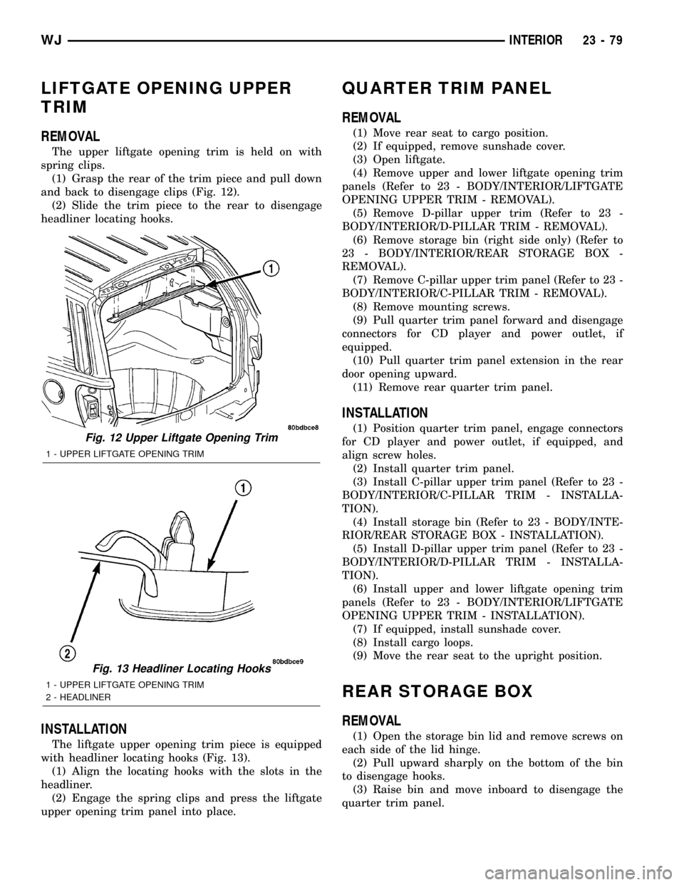
and back to disengage clips (Fig. 12).
(2) Slide the trim piece to the rear to disengage
headliner locating hooks.
INSTALLATION
The liftgate upper opening trim piece is equipped
with headliner locating hooks (Fig. 13).
(1) Align the locating hooks with the slots in the
headliner.
(2) Engage the spring clips and press the liftgate
upper opening trim panel into place.
QUARTER TRIM PANEL
REMOVAL
(1) Move rear seat to cargo position.
(2) If equipped, remove sunshade cover.
(3) Open liftgate.
(4) Remove upper and lower liftgate opening trim
panels (Refer to 23 - BODY/INTERIOR/LIFTGATE
OPENING UPPER TRIM - REMOVAL).
(5) Remove D-pillar upper trim (Refer to 23 -
BODY/INTERIOR/D-PILLAR TRIM - REMOVAL).
(6) Remove storage bin (right side only) (Refer to
23 - BODY/INTERIOR/REAR STORAGE BOX -
REMOVAL).
(7) Remove C-pillar upper trim panel (Refer to 23 -
BODY/INTERIOR/C-PILLAR TRIM - REMOVAL).
(8) Remove mounting screws.
(9) Pull quarter trim panel forward and disengage
connectors for CD player and power outlet, if
equipped.
(10) Pull quarter trim panel extension in the rear
door opening upward.
(11) Remove rear quarter trim panel.
INSTALLATION
(1) Position quarter trim panel, engage connectors
for CD player and power outlet, if equipped, and
align screw holes.
(2) Install quarter trim panel.
(3) Install C-pillar upper trim panel (Refer to 23 -
BODY/INTERIOR/C-PILLAR TRIM - INSTALLA-
TION).
(4) Install storage bin (Refer to 23 - BODY/INTE-
RIOR/REAR STORAGE BOX - INSTALLATION).
(5) Install D-pillar upper trim panel (Refer to 23 -
BODY/INTERIOR/D-PILLAR TRIM - INSTALLA-
TION).
(6) Install upper and lower liftgate opening trim
panels (Refer to 23 - BODY/INTERIOR/LIFTGATE
OPENING UPPER TRIM - INSTALLATION).
(7) If equipped, install sunshade cover.
(8) Install cargo loops.
(9) Move the rear seat to the upright position.
REAR STORAGE BOX
REMOVAL
(1) Open the storage bin lid and remove screws on
each side of the lid hinge.
(2) Pull upward sharply on the bottom of the bin
to disengage hooks.
(3) Raise bin and move inboard to disengage the
quarter trim panel.
Fig. 12 Upper Liftgate Opening Trim
1 - UPPER LIFTGATE OPENING TRIM
Fig. 13 Headliner Locating Hooks
1 - UPPER LIFTGATE OPENING TRIM
2 - HEADLINER
WJINTERIOR 23 - 79
Page 1953 of 2199
INSTALLATION
(1) Position the bin hooks high in the slots on the
quarter trim panel.
(2) Push downward until the bin snaps into place.
(3) Install the hinge screws.
REAR VIEW MIRROR
REMOVAL
(1)If equipped, disconnect mirror harness connector.
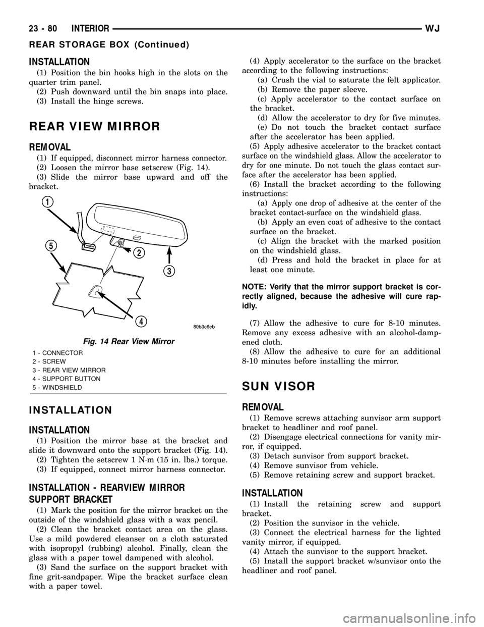
(2) Loosen the mirror base setscrew (Fig. 14).
(3) Slide the mirror base upward and off the
bracket.
INSTALLATION
INSTALLATION
(1) Position the mirror base at the bracket and
slide it downward onto the support bracket (Fig. 14).
(2) Tighten the setscrew 1 N´m (15 in. lbs.) torque.
(3) If equipped, connect mirror harness connector.
INSTALLATION - REARVIEW MIRROR
SUPPORT BRACKET
(1) Mark the position for the mirror bracket on the
outside of the windshield glass with a wax pencil.
(2) Clean the bracket contact area on the glass.
Use a mild powdered cleanser on a cloth saturated
with isopropyl (rubbing) alcohol. Finally, clean the
glass with a paper towel dampened with alcohol.
(3) Sand the surface on the support bracket with
fine grit-sandpaper. Wipe the bracket surface clean
with a paper towel.(4) Apply accelerator to the surface on the bracket
according to the following instructions:
(a) Crush the vial to saturate the felt applicator.
(b) Remove the paper sleeve.
(c) Apply accelerator to the contact surface on
the bracket.
(d) Allow the accelerator to dry for five minutes.
(e) Do not touch the bracket contact surface
after the accelerator has been applied.
(5)
Apply adhesive accelerator to the bracket contact
surface on the windshield glass. Allow the accelerator to
dry for one minute. Do not touch the glass contact sur-
face after the accelerator has been applied.
(6) Install the bracket according to the following
instructions:
(a)
Apply one drop of adhesive at the center of the
bracket contact-surface on the windshield glass.
(b) Apply an even coat of adhesive to the contact
surface on the bracket.
(c) Align the bracket with the marked position
on the windshield glass.
(d) Press and hold the bracket in place for at
least one minute.
NOTE: Verify that the mirror support bracket is cor-
rectly aligned, because the adhesive will cure rap-
idly.
(7) Allow the adhesive to cure for 8-10 minutes.
Remove any excess adhesive with an alcohol-damp-
ened cloth.
(8) Allow the adhesive to cure for an additional
8-10 minutes before installing the mirror.
SUN VISOR
REMOVAL
(1) Remove screws attaching sunvisor arm support
bracket to headliner and roof panel.
(2) Disengage electrical connections for vanity mir-
ror, if equipped.
(3) Detach sunvisor from support bracket.
(4) Remove sunvisor from vehicle.
(5) Remove retaining screw and support bracket.
INSTALLATION
(1) Install the retaining screw and support
bracket.
(2) Position the sunvisor in the vehicle.
(3) Connect the electrical harness for the lighted
vanity mirror, if equipped.
(4) Attach the sunvisor to the support bracket.
(5) Install the support bracket w/sunvisor onto the
headliner and roof panel.
Fig. 14 Rear View Mirror
1 - CONNECTOR
2 - SCREW
3 - REAR VIEW MIRROR
4 - SUPPORT BUTTON
5 - WINDSHIELD
23 - 80 INTERIORWJ
REAR STORAGE BOX (Continued)
Page 1960 of 2199
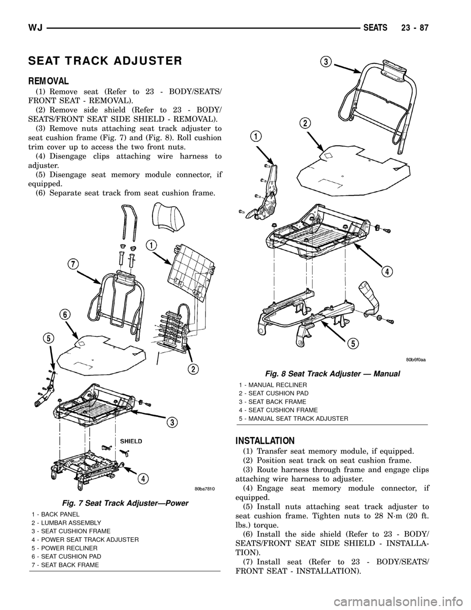
SEAT TRACK ADJUSTER
REMOVAL
(1) Remove seat (Refer to 23 - BODY/SEATS/
FRONT SEAT - REMOVAL).
(2) Remove side shield (Refer to 23 - BODY/
SEATS/FRONT SEAT SIDE SHIELD - REMOVAL).
(3) Remove nuts attaching seat track adjuster to
seat cushion frame (Fig. 7) and (Fig. 8). Roll cushion
trim cover up to access the two front nuts.
(4) Disengage clips attaching wire harness to
adjuster.
(5) Disengage seat memory module connector, if
equipped.
(6) Separate seat track from seat cushion frame.
INSTALLATION
(1) Transfer seat memory module, if equipped.
(2) Position seat track on seat cushion frame.
(3) Route harness through frame and engage clips
attaching wire harness to adjuster.
(4) Engage seat memory module connector, if
equipped.
(5) Install nuts attaching seat track adjuster to
seat cushion frame. Tighten nuts to 28 N´m (20 ft.
lbs.) torque.
(6) Install the side shield (Refer to 23 - BODY/
SEATS/FRONT SEAT SIDE SHIELD - INSTALLA-
TION).
(7) Install seat (Refer to 23 - BODY/SEATS/
FRONT SEAT - INSTALLATION).
Fig. 7 Seat Track AdjusterÐPower
1 - BACK PANEL
2 - LUMBAR ASSEMBLY
3 - SEAT CUSHION FRAME
4 - POWER SEAT TRACK ADJUSTER
5 - POWER RECLINER
6 - SEAT CUSHION PAD
7 - SEAT BACK FRAME
Fig. 8 Seat Track Adjuster Ð Manual
1 - MANUAL RECLINER
2 - SEAT CUSHION PAD
3 - SEAT BACK FRAME
4 - SEAT CUSHION FRAME
5 - MANUAL SEAT TRACK ADJUSTER
WJSEATS 23 - 87
Page 1964 of 2199
REAR SEAT CUSHION COVER
REMOVAL
(1) Remove rear seat cushion (Refer to 23 - BODY/
SEATS/REAR SEAT CUSHION - REMOVAL).
(2) From the underside of the seat, disengage
J-straps attaching cover to seat cushion base panel.
(3) Remove push-in fasteners attaching cushion
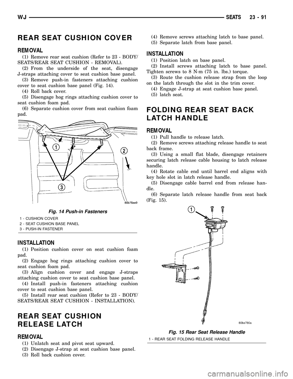
cover to seat cushion base panel (Fig. 14).
(4) Roll back cover.
(5) Disengage hog rings attaching cushion cover to
seat cushion foam pad.
(6) Separate cushion cover from seat cushion foam
pad.
INSTALLATION
(1) Position cushion cover on seat cushion foam
pad.
(2) Engage hog rings attaching cushion cover to
seat cushion foam pad.
(3) Align cushion cover and engage J-straps
attaching cushion cover to seat cushion base panel.
(4) Install push-in fasteners attaching cushion
cover to seat cushion base panel.
(5) Install rear seat cushion (Refer to 23 - BODY/
SEATS/REAR SEAT CUSHION - INSTALLATION).
REAR SEAT CUSHION
RELEASE LATCH
REMOVAL
(1) Unlatch seat and pivot seat upward.
(2) Disengage J-strap at seat cushion base panel.
(3) Roll back cushion cover.(4) Remove screws attaching latch to base panel.
(5) Separate latch from base panel.
INSTALLATION
(1) Position latch on base panel.
(2) Install screws attaching latch to base panel.
Tighten screws to 8 N´m (75 in. lbs.) torque.
(3) Route the cushion release strap from the loop
on the latch through the slot in the trim cover.
(4) Engage J-strap at seat cushion base panel.
(5) latch seat.
FOLDING REAR SEAT BACK
LATCH HANDLE
REMOVAL
(1) Pull handle to release latch.
(2) Remove screws attaching release handle to seat
back frame.
(3) Using a small flat blade, disengage retainers
securing latch release cable housing to latch release
handle.
(4) Rotate cable end until barrel end aligns with
key hole slot in latch release handle.
(5) Disengage cable barrel end from release han-
dle.
(6) Separate latch release handle from seat back
(Fig. 15).
Fig. 14 Push-in Fasteners
1 - CUSHION COVER
2 - SEAT CUSHION BASE PANEL
3 - PUSH-IN FASTENER
Fig. 15 Rear Seat Release Handle
1 - REAR SEAT FOLDING RELEASE HANDLE
WJSEATS 23 - 91