lamp replacement JEEP GRAND CHEROKEE 2003 WJ / 2.G Owner's Guide
[x] Cancel search | Manufacturer: JEEP, Model Year: 2003, Model line: GRAND CHEROKEE, Model: JEEP GRAND CHEROKEE 2003 WJ / 2.GPages: 2199, PDF Size: 76.01 MB
Page 1234 of 2199
(9) Remove the PDC and the right headlamp and
dash wire harness from the engine compartment as a
unit.
DISASSEMBLY
POWER DISTRIBUTION CENTER DISASSEMBLY
PDC HOUSING LOWER COVER REMOVAL
The Power Distribution Center (PDC) cover, the
PDC housing lower cover, the PDC relay wedges, the
PDC relay cassettes and the PDC B(+) terminal stud
module are available for service replacement. The
PDC cover can be simply unlatched and removed
from the PDC housing without the PDC being
removed or disassembled. Service of the remaining
PDC components requires that the PDC be removed
from its mounting and disassembled. Refer toWiring
Repairin Wiring Diagrams for the location of the
wiring repair procedures.
(1) Remove the battery from the battery support.
Refer toBattery Systemfor the location of the bat-
tery removal procedures.
(2) Unlatch and remove the cover from the PDC.
(3) Remove the two nuts that secure the two-holed
eyelet of the battery wire harness PDC take out to
the B(+) terminal studs near the front of the PDC.
(4) Remove the battery wire harness PDC take out
eyelet from the two PDC B(+) terminal studs.
(5) Disengage the latches on the PDC housing
mounts from the tabs on the PDC mounting stan-
chions on the battery support, and pull the PDC
housing upward to disengage the mounts from the
stanchions.
(6) Where the right headlamp and dash wire har-
ness exits the PDC, remove the tape that secures the
wire harness to the trough formation on the PDC
housing lower cover.
(7) Using a trim stick or another suitable wide
flat-bladed tool, gently pry the latches on each side
and the front of the PDC housing that secure the
housing lower cover to the PDC and remove the
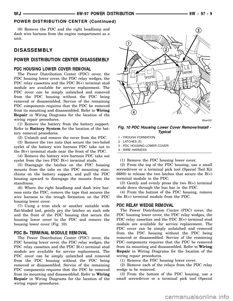
housing lower cover (Fig. 10).
PDC B+ TERMINAL MODULE REMOVAL
The Power Distribution Center (PDC) cover, the
PDC housing lower cover, the PDC relay wedges, the
PDC relay cassettes and the PDC B(+) terminal stud
module are available for service replacement. The
PDC cover can be simply unlatched and removed
from the PDC housing without the PDC being
removed or disassembled. Service of the remaining
PDC components requires that the PDC be removed
from its mounting and disassembled. Refer toWiring
Repairin Wiring Diagrams for the location of the
wiring repair procedures.(1) Remove the PDC housing lower cover.
(2) From the top of the PDC housing, use a small
screwdriver or a terminal pick tool (Special Tool Kit
6680) to release the two latches that secure the B(+)
terminal module in the PDC.
(3) Gently and evenly press the two B(+) terminal
studs down through the bus bar in the PDC.
(4) From the bottom of the PDC housing, remove
the B(+) terminal module from the PDC.
PDC RELAY WEDGE REMOVAL
The Power Distribution Center (PDC) cover, the
PDC housing lower cover, the PDC relay wedges, the
PDC relay cassettes and the PDC B(+) terminal stud
module are available for service replacement. The
PDC cover can be simply unlatched and removed
from the PDC housing without the PDC being
removed or disassembled. Service of the remaining
PDC components requires that the PDC be removed
from its mounting and disassembled. Refer toWiring
Repairin Wiring Diagrams for the location of the
wiring repair procedures.
(1) Remove the PDC housing lower cover.
(2) Remove each of the relays from the PDC relay
wedge to be removed.
(3) From the bottom of the PDC housing, use a
small screwdriver or a terminal pick tool (Special
Fig. 10 PDC Housing Lower Cover Remove/Install -
Typical
1 - TROUGH FORMATION
2 - LATCHES (5)
3 - PDC HOUSING LOWER COVER
4 - WIRE HARNESS
WJ8W-97 POWER DISTRIBUTION 8W - 97 - 9
POWER DISTRIBUTION CENTER (Continued)
Page 1299 of 2199

(9) Lower the engine until it is properly located on
the engine mounts.
(10) Install the through bolts and tighten the nuts.
(11) Lower the jack stand and remove the piece of
wood.
(12) Install the engine flywheel and transmission
torque converter housing access cover.
(13) Install the engine starter motor. (Refer to 8 -
ELECTRICAL/STARTING/STARTER MOTOR -
INSTALLATION).
(14) Connect the exhaust pipe to the hanger and to
the engine exhaust manifold.
(15) Install transmission oil cooling lines (if
equipped) and oxygen sensor wiring supports that
attach to the oil pan studs.
(16) Install the oil pan drain plug (Fig. 81).
Tighten the plug to 34 N´m (25 ft. lbs.) torque.
(17) Lower the vehicle.
(18) Connect negative cable to battery.
(19) Fill the oil pan with engine oil to the specified
level.
WARNING: USE EXTREME CAUTION WHEN THE
ENGINE IS OPERATING. DO NOT STAND IN A
DIRECT LINE WITH THE FAN. DO NOT PUT YOUR
HANDS NEAR THE PULLEYS, BELTS OR FAN. DO
NOT WEAR LOOSE CLOTHING.
(20) Start the engine and inspect for leaks.
ENGINE OIL PRESSURE
SENSOR
DESCRIPTION
The 3±wire, solid-state engine oil pressure sensor
(sending unit) is located in an engine oil pressure
gallery.
OPERATION
The oil pressure sensor uses three circuits. They
are:
²A 5±volt power supply from the Powertrain Con-
trol Module (PCM)
²A sensor ground through the PCM's sensor
return
²A signal to the PCM relating to engine oil pres-
sure
The oil pressure sensor has a 3±wire electrical
function very much like the Manifold Absolute Pres-
sure (MAP) sensor. Meaning different pressures
relate to different output voltages.
A 5±volt supply is sent to the sensor from the PCM
to power up the sensor. The sensor returns a voltage
signal back to the PCM relating to engine oil pres-
sure. This signal is then transferred (bussed) to theinstrument panel on either a CCD or PCI bus circuit
(depending on vehicle line) to operate the oil pressure
gauge and the check gauges lamp. Ground for the
sensor is provided by the PCM through a low-noise
sensor return.
OIL PUMP
REMOVAL
A gear-type oil pump is mounted at the underside
of the cylinder block opposite the No.4 main bearing.
(1) Drain the engine oil.
(2) Remove the oil pan (Refer to 9 - ENGINE/LU-
BRICATION/OIL PAN - REMOVAL).
(3) Remove the pump-to-cylinder block attaching
bolts. Remove the pump assembly with gasket (Fig.
82).
CAUTION: If the oil pump is not to be serviced, DO
NOT disturb position of oil inlet tube and strainer
assembly in pump body. If the tube is moved within
the pump body, a replacement tube and strainer
assembly must be installed to assure an airtight
seal.
Fig. 82 Oil Pump Assembly
1 - OIL FILTER ADAPTOR
2 - BLOCK
3 - GASKET
4 - OIL INLET TUBE
5 - OIL PUMP
6 - STRAINER ASSEMBLY
7 - ATTACHING BOLTS
9 - 56 ENGINE - 4.0LWJ
OIL PAN (Continued)
Page 1409 of 2199
HEAT SHIELDS
DESCRIPTION
Heat shields are needed to protect both the vehicle
and the environment from the high temperatures
developed by the catalytic converter. The catalytic
converter releases additional heat into the exhaust
system. Under severe operating conditions, the tem-
perature increases in the area of the converter. Such
conditions can exist when the engine misfires or oth-
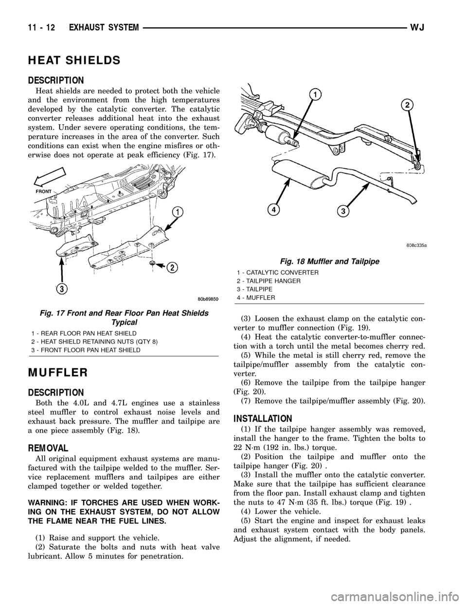
erwise does not operate at peak efficiency (Fig. 17).
MUFFLER
DESCRIPTION
Both the 4.0L and 4.7L engines use a stainless
steel muffler to control exhaust noise levels and
exhaust back pressure. The muffler and tailpipe are
a one piece assembly (Fig. 18).
REMOVAL
All original equipment exhaust systems are manu-
factured with the tailpipe welded to the muffler. Ser-
vice replacement mufflers and tailpipes are either
clamped together or welded together.
WARNING: IF TORCHES ARE USED WHEN WORK-
ING ON THE EXHAUST SYSTEM, DO NOT ALLOW
THE FLAME NEAR THE FUEL LINES.
(1) Raise and support the vehicle.
(2) Saturate the bolts and nuts with heat valve
lubricant. Allow 5 minutes for penetration.(3) Loosen the exhaust clamp on the catalytic con-
verter to muffler connection (Fig. 19).
(4) Heat the catalytic converter-to-muffler connec-
tion with a torch until the metal becomes cherry red.
(5) While the metal is still cherry red, remove the
tailpipe/muffler assembly from the catalytic con-
verter.
(6) Remove the tailpipe from the tailpipe hanger
(Fig. 20).
(7) Remove the tailpipe/muffler assembly (Fig. 20).
INSTALLATION
(1) If the tailpipe hanger assembly was removed,
install the hanger to the frame. Tighten the bolts to
22 N´m (192 in. lbs.) torque.
(2) Position the tailpipe and muffler onto the
tailpipe hanger (Fig. 20) .
(3) Install the muffler onto the catalytic converter.
Make sure that the tailpipe has sufficient clearance
from the floor pan. Install exhaust clamp and tighten
the nuts to 47 N´m (35 ft. lbs.) torque (Fig. 19) .
(4) Lower the vehicle.
(5) Start the engine and inspect for exhaust leaks
and exhaust system contact with the body panels.
Adjust the alignment, if needed.
Fig. 17 Front and Rear Floor Pan Heat Shields
Typical
1 - REAR FLOOR PAN HEAT SHIELD
2 - HEAT SHIELD RETAINING NUTS (QTY 8)
3 - FRONT FLOOR PAN HEAT SHIELD
Fig. 18 Muffler and Tailpipe
1 - CATALYTIC CONVERTER
2 - TAILPIPE HANGER
3 - TAILPIPE
4 - MUFFLER
11 - 12 EXHAUST SYSTEMWJ
Page 1422 of 2199
CAUTION: The fittings on both tools must be in
good condition and free from any small leaks
before performing the proceeding test.
(9) Start engine and bring to normal operating
temperature.
(10) Observe fuel pressure test gauge (or DRB
screen). Normal operating pressure should be 339
kPa 34 kPa (49.2 psi 5 psi).
(11) Shut engine off.
(12) Pressure should not fall below30 psi for five
minutes.
(13) If pressure falls below 30 psi, it must be
determined if a fuel injector, the supply check valve
within the fuel pump module, the fuel filter/pressure
regulator, or a fuel tube/line is leaking.
(14) Again, start engine and bring to normal oper-
ating temperature.
(15) Shut engine off.
(16)Testing for fuel injector or fuel rail leak-
age:Clamp off the rubber hose portion of the 6539
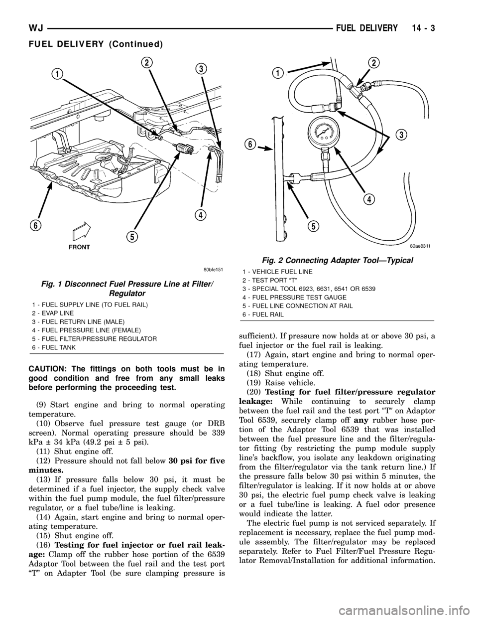
Adaptor Tool between the fuel rail and the test port
ªTº on Adapter Tool (be sure clamping pressure issufficient). If pressure now holds at or above 30 psi, a
fuel injector or the fuel rail is leaking.
(17) Again, start engine and bring to normal oper-
ating temperature.
(18) Shut engine off.
(19) Raise vehicle.
(20)Testing for fuel filter/pressure regulator
leakage:While continuing to securely clamp
between the fuel rail and the test port9T9on Adaptor
Tool 6539, securely clamp offanyrubber hose por-
tion of the Adaptor Tool 6539 that was installed
between the fuel pressure line and the filter/regula-
tor fitting (by restricting the pump module supply
line's backflow, you isolate any leakdown originating
from the filter/regulator via the tank return line.) If
the pressure falls below 30 psi within 5 minutes, the
filter/regulator is leaking. If it now holds at or above
30 psi, the electric fuel pump check valve is leaking
or a fuel tube/line is leaking. A fuel odor presence
would indicate the latter.
The electric fuel pump is not serviced separately. If
replacement is necessary, replace the fuel pump mod-
ule assembly. The filter/regulator may be replaced
separately. Refer to Fuel Filter/Fuel Pressure Regu-
lator Removal/Installation for additional information.
Fig. 1 Disconnect Fuel Pressure Line at Filter/
Regulator
1 - FUEL SUPPLY LINE (TO FUEL RAIL)
2 - EVAP LINE
3 - FUEL RETURN LINE (MALE)
4 - FUEL PRESSURE LINE (FEMALE)
5 - FUEL FILTER/PRESSURE REGULATOR
6 - FUEL TANK
Fig. 2 Connecting Adapter ToolÐTypical
1 - VEHICLE FUEL LINE
2 - TEST PORT ªTº
3 - SPECIAL TOOL 6923, 6631, 6541 OR 6539
4 - FUEL PRESSURE TEST GAUGE
5 - FUEL LINE CONNECTION AT RAIL
6 - FUEL RAIL
WJFUEL DELIVERY 14 - 3
FUEL DELIVERY (Continued)
Page 1544 of 2199
CONDITION POSSIBLE CAUSES CORRECTION
NO START IN PARK
OR NEUTRAL1. Gearshift Linkage/Cable
Mis-adjusted.1. Adjust linkage/cable.
2. Neutral Sense Wire Open/Cut. 2. Check continuity with test lamp. Repair as
required.
3. Park/Neutral Switch, or
Transmission Range Sensor Faulty.3. Refer to service section for test and
replacement procedure.
4. Park/Neutral Switch, or
Transmission Range Sensor
Connection Faulty.4. Connectors spread open. Repair.
5. Valve Body Manual Lever
Assembly Bent/Worn/Broken.5. Inspect lever assembly and replace if damaged.
NO REVERSE (OR
SLIPS IN REVERSE)1. Direct Clutch Pack (front clutch)
Worn.1. Disassemble unit and rebuild clutch pack.
2. Rear Band Mis-adjusted. 2. Adjust band.
3. Front Clutch Malfunctioned/
Burned.3. Air-pressure test clutch operation. Remove and
rebuild if necessary.
4. Overdrive Thrust Bearing
Failure.4. Disassemble geartrain and replace bearings.
5. Direct Clutch Spring Collapsed/
Broken.5. Remove and disassemble unit. Check clutch
position and replace spring.
WJAUTOMATIC TRANSMISSION - 42RE 21 - 25
AUTOMATIC TRANSMISSION - 42RE (Continued)
Page 1601 of 2199
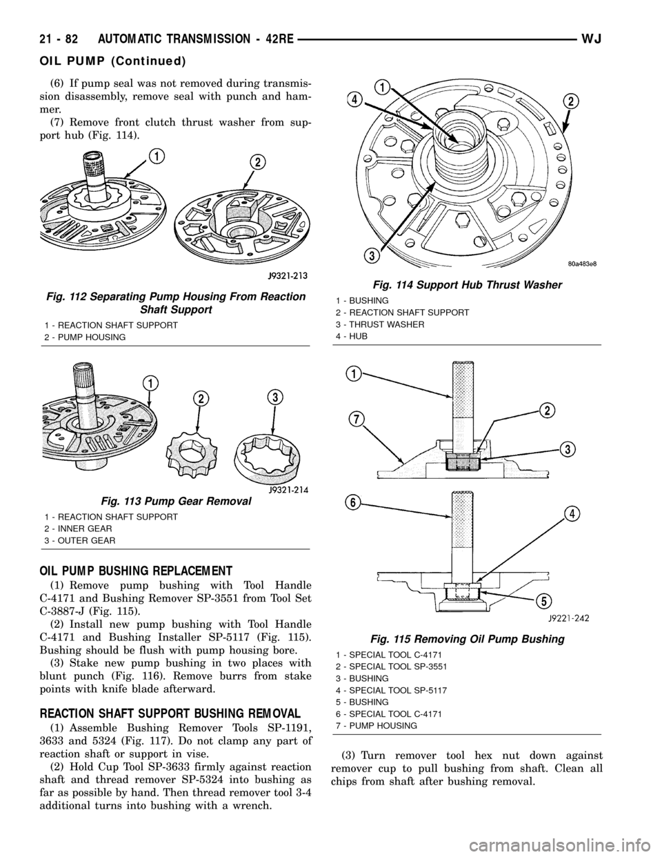
(6) If pump seal was not removed during transmis-
sion disassembly, remove seal with punch and ham-
mer.
(7) Remove front clutch thrust washer from sup-
port hub (Fig. 114).
OIL PUMP BUSHING REPLACEMENT
(1) Remove pump bushing with Tool Handle
C-4171 and Bushing Remover SP-3551 from Tool Set
C-3887-J (Fig. 115).
(2) Install new pump bushing with Tool Handle
C-4171 and Bushing Installer SP-5117 (Fig. 115).
Bushing should be flush with pump housing bore.
(3) Stake new pump bushing in two places with
blunt punch (Fig. 116). Remove burrs from stake
points with knife blade afterward.
REACTION SHAFT SUPPORT BUSHING REMOVAL
(1) Assemble Bushing Remover Tools SP-1191,
3633 and 5324 (Fig. 117). Do not clamp any part of
reaction shaft or support in vise.
(2) Hold Cup Tool SP-3633 firmly against reaction
shaft and thread remover SP-5324 into bushing as
far as possible by hand. Then thread remover tool 3-4
additional turns into bushing with a wrench.(3) Turn remover tool hex nut down against
remover cup to pull bushing from shaft. Clean all
chips from shaft after bushing removal.
Fig. 112 Separating Pump Housing From Reaction
Shaft Support
1 - REACTION SHAFT SUPPORT
2 - PUMP HOUSING
Fig. 113 Pump Gear Removal
1 - REACTION SHAFT SUPPORT
2 - INNER GEAR
3 - OUTER GEAR
Fig. 114 Support Hub Thrust Washer
1 - BUSHING
2 - REACTION SHAFT SUPPORT
3 - THRUST WASHER
4 - HUB
Fig. 115 Removing Oil Pump Bushing
1 - SPECIAL TOOL C-4171
2 - SPECIAL TOOL SP-3551
3 - BUSHING
4 - SPECIAL TOOL SP-5117
5 - BUSHING
6 - SPECIAL TOOL C-4171
7 - PUMP HOUSING
21 - 82 AUTOMATIC TRANSMISSION - 42REWJ
OIL PUMP (Continued)
Page 2122 of 2199
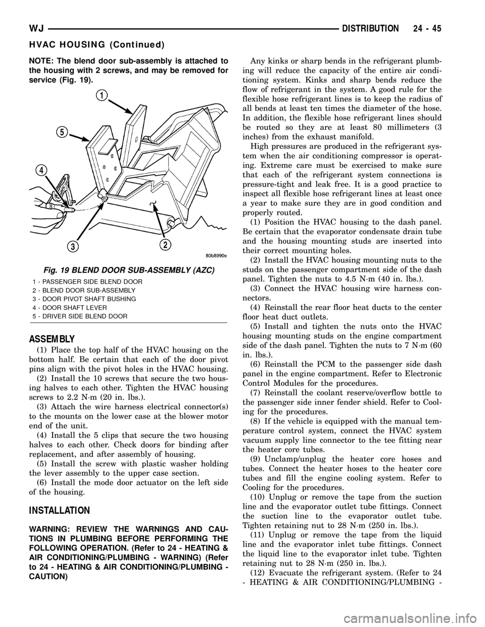
NOTE: The blend door sub-assembly is attached to
the housing with 2 screws, and may be removed for
service (Fig. 19).
ASSEMBLY
(1) Place the top half of the HVAC housing on the
bottom half. Be certain that each of the door pivot
pins align with the pivot holes in the HVAC housing.
(2) Install the 10 screws that secure the two hous-
ing halves to each other. Tighten the HVAC housing
screws to 2.2 N´m (20 in. lbs.).
(3) Attach the wire harness electrical connector(s)
to the mounts on the lower case at the blower motor
end of the unit.
(4) Install the 5 clips that secure the two housing
halves to each other. Check doors for binding after
replacement, and after assembly of housing.
(5) Install the screw with plastic washer holding
the lever assembly to the upper case section.
(6) Install the mode door actuator on the left side
of the housing.
INSTALLATION
WARNING: REVIEW THE WARNINGS AND CAU-
TIONS IN PLUMBING BEFORE PERFORMING THE
FOLLOWING OPERATION. (Refer to 24 - HEATING &
AIR CONDITIONING/PLUMBING - WARNING) (Refer
to 24 - HEATING & AIR CONDITIONING/PLUMBING -
CAUTION)Any kinks or sharp bends in the refrigerant plumb-
ing will reduce the capacity of the entire air condi-
tioning system. Kinks and sharp bends reduce the
flow of refrigerant in the system. A good rule for the
flexible hose refrigerant lines is to keep the radius of
all bends at least ten times the diameter of the hose.
In addition, the flexible hose refrigerant lines should
be routed so they are at least 80 millimeters (3
inches) from the exhaust manifold.
High pressures are produced in the refrigerant sys-
tem when the air conditioning compressor is operat-
ing. Extreme care must be exercised to make sure
that each of the refrigerant system connections is
pressure-tight and leak free. It is a good practice to
inspect all flexible hose refrigerant lines at least once
a year to make sure they are in good condition and
properly routed.
(1) Position the HVAC housing to the dash panel.
Be certain that the evaporator condensate drain tube
and the housing mounting studs are inserted into
their correct mounting holes.
(2) Install the HVAC housing mounting nuts to the
studs on the passenger compartment side of the dash
panel. Tighten the nuts to 4.5 N´m (40 in. lbs.).
(3) Connect the HVAC housing wire harness con-
nectors.
(4) Reinstall the rear floor heat ducts to the center
floor heat duct outlets.
(5) Install and tighten the nuts onto the HVAC
housing mounting studs on the engine compartment
side of the dash panel. Tighten the nuts to 7 N´m (60
in. lbs.).
(6) Reinstall the PCM to the passenger side dash
panel in the engine compartment. Refer to Electronic
Control Modules for the procedures.
(7) Reinstall the coolant reserve/overflow bottle to
the passenger side inner fender shield. Refer to Cool-
ing for the procedures.
(8) If the vehicle is equipped with the manual tem-
perature control system, connect the HVAC system
vacuum supply line connector to the tee fitting near
the heater core tubes.
(9) Unclamp/unplug the heater core hoses and
tubes. Connect the heater hoses to the heater core
tubes and fill the engine cooling system. Refer to
Cooling for the procedures.
(10) Unplug or remove the tape from the suction
line and the evaporator outlet tube fittings. Connect
the suction line to the evaporator outlet tube.
Tighten retaining nut to 28 N´m (250 in. lbs.).
(11) Unplug or remove the tape from the liquid
line and the evaporator inlet tube fittings. Connect
the liquid line to the evaporator inlet tube. Tighten
retaining nut to 28 N´m (250 in. lbs.).
(12) Evacuate the refrigerant system. (Refer to 24
- HEATING & AIR CONDITIONING/PLUMBING -
Fig. 19 BLEND DOOR SUB-ASSEMBLY (AZC)
1 - PASSENGER SIDE BLEND DOOR
2 - BLEND DOOR SUB-ASSEMBLY
3 - DOOR PIVOT SHAFT BUSHING
4 - DOOR SHAFT LEVER
5 - DRIVER SIDE BLEND DOOR
WJDISTRIBUTION 24 - 45
HVAC HOUSING (Continued)