4.7 v8 engine JEEP GRAND CHEROKEE 2003 WJ / 2.G Repair Manual
[x] Cancel search | Manufacturer: JEEP, Model Year: 2003, Model line: GRAND CHEROKEE, Model: JEEP GRAND CHEROKEE 2003 WJ / 2.GPages: 2199, PDF Size: 76.01 MB
Page 412 of 2199

INSTALLATION
4.7L High-Output Engine Only
NOTE: The left sensor is identified by an identifica-
tion tag (LEFT). It is also identified by a larger bolt
head. The Powertrain Control Module (PCM) must
have and know the correct sensor left/right posi-
tions. Do not mix the sensor locations.
(1) Thoroughly clean knock sensor mounting holes.
(2) Install sensors (Fig. 22) into cylinder block.
NOTE: Over or under tightening the sensor mount-
ing bolts will affect knock sensor performance, pos-
sibly causing improper spark control. Always use
the specified torque when installing the knock sen-
sors. The torque for the knock senor bolt is rela-
tively light for an 8mm bolt.
NOTE: Note foam strip on bolt threads. This foam is
used only to retain the bolts to sensors for plant
assembly. It is not used as a sealant. Do not apply
any adhesive, sealant or thread locking compound
to these bolts.
(3) Install and tighten mounting bolts.Bolt
torque is critical.Refer to torque specification.
(4) Install intake manifold. Refer to Engine sec-
tion.
(5) Connect knock sensor pigtail wiring harness to
engine wiring harness near right / rear of intake
manifold (Fig. 23).
SPARK PLUG
DESCRIPTION
Both the 4.0L 6-cylinder and the 4.7L V-8 engine
use resistor type spark plugs. Standard 4.7L V-8
engines are equipped with ªfired in suppressor sealº
type spark plugs using a copper core ground elec-
trode. High-Output (H.O.) 4.7L V-8 engines are
equipped with unique plugs using a platinum rivet
located on the tip of the center electrode.
Because of the use of an aluminum cylinder head
on the 4.7L engine, spark plug torque is very critical.
To prevent possible pre-ignition and/or mechanical
engine damage, the correct type/heat range/number
spark plug must be used.Do not substitute any
other spark plug on the 4.7L H.O. engine. Seri-
ous engine damage may occur.
Plugs on both engines have resistance values rang-
ing from 6,000 to 20,000 ohms (when checked with at
least a 1000 volt spark plug tester).Do not use an
ohmmeter to check the resistance values of thespark plugs. Inaccurate readings will result.
Remove the spark plugs and examine them for
burned electrodes and fouled, cracked or broken por-
celain insulators. Keep plugs arranged in the order
in which they were removed from the engine. A sin-
gle plug displaying an abnormal condition indicates
that a problem exists in the corresponding cylinder.
Replace spark plugs at the intervals recommended in
Group O, Lubrication and Maintenance.
EXCEPT 4.7L H.O. ENGINE :Spark plugs that
have low mileage may be cleaned and reused if not
otherwise defective, carbon or oil fouled. Also refer to
Spark Plug Conditions.4.7L H.O. ENGINE :Never
clean spark plugs on the 4.7L H.O. engine. Damage
to the platinum rivet will result.
CAUTION: EXCEPT 4.7L H.O. ENGINE : Never use a
motorized wire wheel brush to clean the spark
plugs. Metallic deposits will remain on the spark
plug insulator and will cause plug misfire.
H.O. Gap Adjustment:If equipped with the 4.7L
H.O. engine, do not use a wire-type gapping tool as
damage to the platinum rivet on the center electrode
may occur. Use a tapered-type gauge (Fig. 24).
DIAGNOSIS AND TESTING - SPARK PLUG
CONDITIONS
NORMAL OPERATING
The few deposits present on the spark plug will
probably be light tan or slightly gray in color. This is
evident with most grades of commercial gasoline
Fig. 24 PLUG GAP - 4.7L H.O.
1 - TAPER GAUGE
WJIGNITION CONTROL 8I - 15
KNOCK SENSOR (Continued)
Page 415 of 2199

SPARK PLUG OVERHEATING
Overheating is indicated by a white or gray center
electrode insulator that also appears blistered (Fig.
31). The increase in electrode gap will be consider-
ably in excess of 0.001 inch per 2000 miles of opera-
tion. This suggests that a plug with a cooler heat
range rating should be used. Over advanced ignition
timing, detonation and cooling system malfunctions
can also cause spark plug overheating.
CAUTION: If the engine is equipped with copper
core ground electrode, or platinum tipped spark
plugs, they must be replaced with the same type/
number spark plug as the original. If another spark
plug is substituted, pre-ignition will result.
REMOVAL
CAUTION: If equipped with a 4.7L H.O. (High-Out-
put) engine, never substitute the original platinum
tipped spark plug with a different part number. Seri-
ous engine damage may result.
On the 4.0L 6±cylinder engine, the spark plugs are
located below the coil rail assembly. On the 4.7L V±8
engine, each individual spark plug is located under
each ignition coil.
(1) 4.0L 6±Cylinder Engine: Prior to removing
spark plug, spray compressed air around spark plug
hole and area around spark plug. This will help pre-
vent foreign material from entering combustion
chamber.
(2) 4.7L V±8 Engine: Prior to removing spark plug,
spray compressed air around base of ignition coil at
cylinder head. This will help prevent foreign material
from entering combustion chamber.
(3) On the 4.0L engine the coil rail assembly must
be removed to gain access to any/all spark plug.
Refer to Ignition Coil Removal/Installation. On the4.7L V-8 engine each individual ignition coil must be
removed to gain access to each spark plug. Refer to
Ignition Coil Removal/Installation.
(4) Remove spark plug from cylinder head using a
quality socket with a rubber or foam insert. If
equipped with a 4.7L V-8 engine, also check condition
of coil o-ring and replace as necessary.
(5) Inspect spark plug condition. Refer to Spark
Plug Conditions.
CLEANING
Except 4.7L H.O. Engine:The plugs may be
cleaned using commercially available spark plug
cleaning equipment. After cleaning, file center elec-
trode flat with a small point file or jewelers file
before adjusting gap.
CAUTION: Never use a motorized wire wheel brush
to clean spark plugs. Metallic deposits will remain
on spark plug insulator and will cause plug misfire.
4.7L H.O. Engine:Never clean spark plugs on the
4.7L H.O. engine. Damage to the platinum rivet on
the center electrode will result.
INSTALLATION
CAUTION: The standard 4.7L V-8 engine is
equipped with copper core ground electrode spark
plugs. They must be replaced with the same type/
number spark plug as the original. If another spark
plug is substituted, pre-ignition will result.
CAUTION: If equipped with a 4.7L H.O. (High-Out-
put) engine, never substitute the original platinum
tipped spark plug with a different type/part number.
Serious engine damage may result.
Special care should be taken when installing spark
plugs into cylinder head spark plug wells. Be sure
plugs do not drop into plug wells as ground straps
may be bent resulting in a change in plug gap, or
electrodes can be damaged.
Always tighten spark plugs to specified torque. Over
tightening can cause distortion resulting in a change
in spark plug gap or a cracked porcelain insulator.
(1) Start spark plug into cylinder head by hand to
avoid cross threading.
(2) 4.0L 6±Cylinder Engine: Tighten spark plugs to
35-41 N´m (26-30 ft. lbs.) torque.
(3) 4.7L V±8 Engine: Tighten spark plugs to 27
N´m (20 ft. lbs.) torque.
(4)
4.7L V±8 Engine: Before installing coil(s), check
condition of coil o-ring and replace as necessary. To aid
in coil installation, apply silicone to coil o-ring.
(5) Install ignition coil(s). Refer to Ignition Coil
Removal/Installation.
Fig. 31 SPARK PLUG OVERHEATING
1 - BLISTERED WHITE OR GRAY COLORED INSULATOR
8I - 18 IGNITION CONTROLWJ
SPARK PLUG (Continued)
Page 582 of 2199

SPEED CONTROL
TABLE OF CONTENTS
page page
SPEED CONTROL
DESCRIPTION..........................1
OPERATION............................1
DIAGNOSIS AND TESTING - ROAD TEST.....2
SPECIFICATIONS
TORQUE - SPEED CONTROL.............3
CABLE
DESCRIPTION..........................3
OPERATION............................3
REMOVAL
REMOVAL - 4.0L.......................3
REMOVAL - 4.7L.......................3
INSTALLATION
INSTALLATION - 4.0L...................4
INSTALLATION - 4.7L...................4
SERVO
DESCRIPTION..........................5OPERATION............................5
REMOVAL.............................5
INSTALLATION..........................6
SWITCH
DESCRIPTION..........................7
OPERATION............................7
REMOVAL.............................7
INSTALLATION..........................7
VACUUM RESERVOIR
DESCRIPTION..........................8
OPERATION............................8
DIAGNOSIS AND TESTING - VACUUM
RESERVOIR..........................8
REMOVAL.............................8
INSTALLATION..........................9
SPEED CONTROL
DESCRIPTION
The speed control system is electronically con-
trolled and vacuum operated. Electronic control of
the speed control system is integrated into the Pow-
ertrain Control Module (PCM). The controls consist
of two steering wheel mounted switches. The
switches are labeled: ON/OFF, RES/ACCEL, SET,
COAST, and CANCEL.
The system is designed to operate at speeds above
30 mph (50 km/h).
WARNING: THE USE OF SPEED CONTROL IS NOT
RECOMMENDED WHEN DRIVING CONDITIONS DO
NOT PERMIT MAINTAINING A CONSTANT SPEED,
SUCH AS IN HEAVY TRAFFIC OR ON ROADS THAT
ARE WINDING, ICY, SNOW COVERED, OR SLIP-
PERY.
OPERATION
When speed control is selected by depressing the
ON switch, the PCM allows a set speed to be stored
in PCM RAM for speed control. To store a set speed,
depress the SET switch while the vehicle is moving
at a speed between 35 and 85 mph. In order for the
speed control to engage, the brakes cannot be
applied, nor can the gear selector be indicating the
transmission is in Park or Neutral.
The speed control can be disengaged manually by:
²Stepping on the brake pedal
²Depressing the OFF switch
²Depressing the CANCEL switch.
²Depressing the clutch pedal (if equipped).
NOTE: Depressing the OFF switch or turning off the
ignition switch will erase the set speed stored in
the PCM.
For added safety, the speed control system is pro-
grammed to disengage for any of the following condi-
tions:
²An indication of Park or Neutral
²A rapid increase rpm (indicates that the clutch
has been disengaged)
²Excessive engine rpm (indicates that the trans-
mission may be in a low gear)
²The speed signal increases at a rate of 10 mph
per second (indicates that the coefficient of friction
between the road surface and tires is extremely low)
WJSPEED CONTROL 8P - 1
Page 584 of 2199

SPECIFICATIONS
TORQUE - SPEED CONTROL
DESCRIPTION N-m Ft. Lbs. In. Lbs.
Servo Mounting Bracket-to-
Servo Nuts8.5 75
Servo Mounting Bracket-to-
Body Nuts28 6 250 50
Switch Module Mounting
Screws.6-1 6-9
Vacuum Reservoir Mounting
Bolts325
CABLE
DESCRIPTION
The speed control servo cable is connected between
the speed control vacuum servo diaphragm and the
throttle body control linkage.
OPERATION
This cable causes the throttle control linkage to
open or close the throttle valve in response to move-
ment of the vacuum servo diaphragm.
REMOVAL
REMOVAL - 4.0L
(1) Disconnect negative battery cable at battery.
(2) Remove air box housing from throttle body.
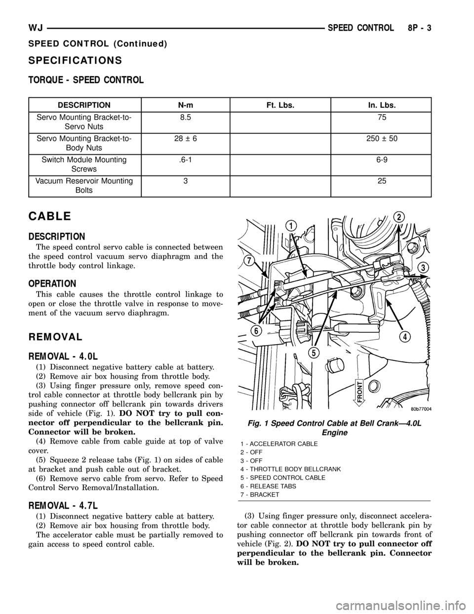
(3) Using finger pressure only, remove speed con-
trol cable connector at throttle body bellcrank pin by
pushing connector off bellcrank pin towards drivers
side of vehicle (Fig. 1).DO NOT try to pull con-
nector off perpendicular to the bellcrank pin.
Connector will be broken.
(4) Remove cable from cable guide at top of valve
cover.
(5) Squeeze 2 release tabs (Fig. 1) on sides of cable
at bracket and push cable out of bracket.
(6) Remove servo cable from servo. Refer to Speed
Control Servo Removal/Installation.
REMOVAL - 4.7L
(1) Disconnect negative battery cable at battery.
(2) Remove air box housing from throttle body.
The accelerator cable must be partially removed to
gain access to speed control cable.(3) Using finger pressure only, disconnect accelera-
tor cable connector at throttle body bellcrank pin by
pushing connector off bellcrank pin towards front of
vehicle (Fig. 2).DO NOT try to pull connector off
perpendicular to the bellcrank pin. Connector
will be broken.
Fig. 1 Speed Control Cable at Bell CrankÐ4.0L
Engine
1 - ACCELERATOR CABLE
2 - OFF
3 - OFF
4 - THROTTLE BODY BELLCRANK
5 - SPEED CONTROL CABLE
6 - RELEASE TABS
7 - BRACKET
WJSPEED CONTROL 8P - 3
SPEED CONTROL (Continued)
Page 585 of 2199

(4) Lift accelerator cable from top of cable cam
(Fig. 2).
(5) Press tab (Fig. 3) to release plastic cable mount
from bracket.Press on tab only enough to
release cable from bracket. If tab is pressed too
much, it will be broken.Slide plastic mount (Fig.
3) towards passenger side of vehicle to remove cable
from bracket.
(6) Using finger pressure only, disconnect speed
control cable connector at throttle body bellcrank pin
by pushing connector off bellcrank pin towards front
of vehicle (Fig. 2).DO NOT try to pull connector
off perpendicular to the bellcrank pin. Connec-
tor will be broken.
(7) Slide speed control cable plastic mount towards
passenger side of vehicle to remove cable from
bracket (Fig. 4).
(8) Remove servo cable from servo. Refer to Speed
Control Servo Removal/Installation.
INSTALLATION
INSTALLATION - 4.0L
(1) Install end of cable to speed control servo.
Refer to Speed Control Servo Removal/Installation.
(2) Install cable into mounting bracket (snaps in).
(3) Install speed control cable connector at throttle
body bellcrank pin (snaps on).
(4) Connect negative battery cable at battery.
(5) Before starting engine, operate accelerator
pedal to check for any binding.
INSTALLATION - 4.7L
(1) Install end of cable to speed control servo.
Refer to Speed Control Servo Removal/Installation.
(2) Slide speed control cable plastic mount into
bracket.
(3) Install speed control cable connector onto throt-
tle body bellcrank pin (snaps on).
(4) Slide accelerator cable plastic mount into
bracket. Continue sliding until tab (Fig. 3) is aligned
to hole in mounting bracket.
(5) Route accelerator cable over top of cable cam
(Fig. 2).
(6) Install accelerator cable connector onto throttle
body bellcrank pin (snaps on).
(7) Install air box housing to throttle body.
Fig. 2 Cable Connectors at Bell CrankÐ4.7L V-8
Engine
1 - THROTTLE BODY
2 - SPEED CONTROL CABLE CONNECTOR
3 - OFF
4 - OFF
5 - ACCELERATOR CABLE CONNECTOR
6 - CABLE CAM
7 - BELLCRANK
Fig. 3 Accelerator Cable Release TabÐ4.7L V-8
Engine
1 - ACCELERATOR CABLE
2 - PLASTIC CABLE MOUNT
3 - PRESS TAB FOR REMOVAL
4 - CABLE BRACKET
5 - SLIDE FOR REMOVAL
8P - 4 SPEED CONTROLWJ
CABLE (Continued)
Page 586 of 2199

(8) Connect negative battery cable at battery.
(9) Before starting engine, operate accelerator
pedal to check for any binding.
SERVO
DESCRIPTION
The servo unit consists of a solenoid valve body,
and a vacuum chamber. The solenoid valve body con-
tains three solenoids:
²Vacuum
²Vent
²Dump
The vacuum chamber contains a diaphragm with a
cable attached to control the throttle linkage.
OPERATION
The Powertrain Control Module (PCM) controls the
solenoid valve body. The solenoid valve body controls
the application and release of vacuum to the dia-
phragm of the vacuum servo. The servo unit cannot
be repaired and is serviced only as a complete assem-
bly.
Power is supplied to the servo's by the PCM
through the brake switch. The PCM controls the
ground path for the vacuum and vent solenoids.The dump solenoid is energized anytime it receives
power. If power to the dump solenoid is interrupted,
the solenoid dumps vacuum in the servo. This pro-
vides a safety backup to the vent and vacuum sole-
noids.
The vacuum and vent solenoids must be grounded
at the PCM to operate. When the PCM grounds the
vacuum servo solenoid, the solenoid allows vacuum
to enter the servo and pull open the throttle plate
using the cable. When the PCM breaks the ground,
the solenoid closes and no more vacuum is allowed to
enter the servo. The PCM also operates the vent sole-
noid via ground. The vent solenoid opens and closes a
passage to bleed or hold vacuum in the servo as
required.
The PCM duty cycles the vacuum and vent sole-
noids to maintain the set speed, or to accelerate and
decelerate the vehicle. To increase throttle opening,
the PCM grounds the vacuum and vent solenoids. To
decrease throttle opening, the PCM removes the
grounds from the vacuum and vent solenoids. When
the brake is released, if vehicle speed exceeds 30
mph to resume, 35 mph to set, and the RES/ACCEL
switch has been depressed, ground for the vent and
vacuum circuits is restored.
REMOVAL
The speed control servo is attached to a bracket.
The bracket and servo assembly are located below
the battery tray.
(1) Disconnect negative battery cable at battery.
(2) Disconnect positive battery cable at battery.
(3) Remove air cleaner housing at top of throttle
body and disconnect servo cable at throttle body.
Refer to Servo Cable Removal/Installation.
(4) Remove battery from battery tray.
(5) Disconnect wiring at battery tray.
(6) Disconnect positive battery cable at Power Dis-
tribution Center (PDC).
(7) Loosen PDC at battery tray.
(8) Remove 4 battery tray bolts. One of these bolts
attaches to speed control bracket flange that sup-
ports battery tray. While removing battery tray, dis-
connect battery temperature sensor electrical
connector at sensor.
(9) Disconnect vacuum line at servo vacuum hose
fitting (Fig. 5) .
(10) Disconnect electrical connector at servo (Fig.
5) .
If servo and mounting bracket are being removed
as one assembly, remove two mounting nuts (Fig. 5) .
These are located above right-front tire. Remove
inner fender clips and pry inner fender back slightly
to gain access to mounting nuts.
Fig. 4 Speed Control Cable at BracketÐ4.7L V-8
Engine
1 - PLASTIC CABLE MOUNT
2 - SPEED CONTROL CABLE
3 - BRACKET
4 - SLIDE FOR REMOVAL
WJSPEED CONTROL 8P - 5
CABLE (Continued)
Page 1050 of 2199

Component Page
DRIVER SEAT BELT SWITCH........ 8W-80-74
DRIVER SIDE IMPACT SENSOR...... 8W-80-74
EGR SOLENOID (DIESEL)........... 8W-80-74
ELECTRIC BRAKE
(EXCEPT BUILT-UP-EXPORT)...... 8W-80-74
ELECTRONIC SPEED CONTROL
SERVO ......................... 8W-80-74
ENGINE CONTROL MODULE C1
(DIESEL)....................... 8W-80-75
ENGINE CONTROL MODULE C2
(DIESEL)....................... 8W-80-76
ENGINE COOLANT TEMPERATURE
SENSOR (DIESEL)................ 8W-80-77
ENGINE COOLANT TEMPERATURE
SENSOR (GAS)................... 8W-80-77
ENGINE OIL PRESSURE
SENSOR (DIESEL)................ 8W-80-77
ENGINE OIL PRESSURE
SENSOR (GAS)................... 8W-80-78
EVAP/PURGE SOLENOID (GAS)....... 8W-80-78
FRONT POWER OUTLET............ 8W-80-78
FRONT WASHER PUMP............. 8W-80-78
FRONT WIPER MOTOR............. 8W-80-78
FUEL INJECTOR NO. 1 (DIESEL)..... 8W-80-79
FUEL INJECTOR NO. 1 (GAS)........ 8W-80-79
FUEL INJECTOR NO. 2 (DIESEL)..... 8W-80-79
FUEL INJECTOR NO. 2 (GAS)........ 8W-80-79
FUEL INJECTOR NO. 3 (DIESEL)..... 8W-80-79
FUEL INJECTOR NO. 3 (GAS)........ 8W-80-80
FUEL INJECTOR NO. 4 (DIESEL)..... 8W-80-80
FUEL INJECTOR NO. 4 (GAS)........ 8W-80-80
FUEL INJECTOR NO. 5 (DIESEL)..... 8W-80-80
FUEL INJECTOR NO. 5 (GAS)........ 8W-80-81
FUEL INJECTOR NO. 6 (GAS)........ 8W-80-81
FUEL INJECTOR NO. 7 (4.7L)........ 8W-80-81
FUEL INJECTOR NO. 8 (4.7L)........ 8W-80-81
FUEL PRESSURE SENSOR (DIESEL) . . 8W-80-82
FUEL PRESSURE SOLENOID
(DIESEL)....................... 8W-80-82
FUEL PUMP MODULE (GAS)......... 8W-80-82
FUEL TANK MODULE (DIESEL)...... 8W-80-82
GENERATOR (DIESEL).............. 8W-80-82
GENERATOR (GAS)................. 8W-80-83
GLOVE BOX LAMP................. 8W-80-83
HEADLAMP LEVELING SWITCH
(BUILT-UP-EXPORT).............. 8W-80-83
HOOD AJAR SWITCH
(BUILT-UP-EXPORT).............. 8W-80-83
HORN NO. 1....................... 8W-80-83
HORN NO. 2....................... 8W-80-84
HYDRAULIC COOLING MODULE..... 8W-80-84
IDLE AIR CONTROL MOTOR......... 8W-80-84
IGNITION SWITCH C1.............. 8W-80-84
IGNITION SWITCH C2.............. 8W-80-84
INPUT SPEED SENSOR (4.7L)........ 8W-80-85Component Page
INSTRUMENT CLUSTER............ 8W-80-85
INTAKE AIR TEMPERATURE
SENSOR (DIESEL)................ 8W-80-85
INTAKE AIR TEMPERATURE
SENSOR (GAS)................... 8W-80-85
INTAKE PORT SWIRL ACTUATOR
(DIESEL)....................... 8W-80-86
INTRUSION TRANSCEIVER MODULE
(BUILT-UP-EXPORT).............. 8W-80-86
JUNCTION BLOCK BODY
CONTROL MODULE.............. 8W-80-86
JUNCTION BLOCK C1.............. 8W-80-87
JUNCTION BLOCK C2 (LHD)......... 8W-80-88
JUNCTION BLOCK C2 (RHD)......... 8W-80-89
JUNCTION BLOCK C3.............. 8W-80-90
JUNCTION BLOCK C4.............. 8W-80-91
JUNCTION BLOCK C5.............. 8W-80-91
KNOCK SENSOR................... 8W-80-91
LEAK DETECTION PUMP (EXCEPT
BUILT-UP-EXPORT)............... 8W-80-91
LEFT COURTESY LAMP............. 8W-80-91
LEFT DOOR HANDLE COURTESY
LAMP.......................... 8W-80-92
LEFT FOG LAMP................... 8W-80-92
LEFT FRONT DOOR SPEAKER....... 8W-80-92
LEFT FRONT IMPACT SENSOR....... 8W-80-92
LEFT FRONT PARK LAMP........... 8W-80-92
LEFT FRONT PARK/TURN SIGNAL LAMP
(EXCEPT BUILT-UP-EXPORT)...... 8W-80-93
LEFT FRONT SIDE MARKER LAMP
(EXCEPT BUILT-UP-EXPORT)...... 8W-80-93
LEFT FRONT TURN SIGNAL LAMP
(BUILT-UP-EXPORT).............. 8W-80-93
LEFT FRONT WHEEL SPEED
SENSOR........................ 8W-80-93
LEFT HEADLAMP LEVELING MOTOR
(BUILT-UP-EXPORT).............. 8W-80-94
LEFT HIGH BEAM HEADLAMP....... 8W-80-94
LEFT INSTRUMENT PANEL SPEAKER . 8W-80-94
LEFT LIFTGATE AJAR SWITCH....... 8W-80-94
LEFT LOW BEAM HEADLAMP....... 8W-80-94
LEFT MULTI-FUNCTION SWITCH.... 8W-80-95
LEFT REAR DOOR LOCK
MOTOR/AJAR SWITCH............ 8W-80-95
LEFT REAR DOOR SPEAKER......... 8W-80-95
LEFT REAR LAMP ASSEMBLY........ 8W-80-95
LEFT REAR WHEEL SPEED
SENSOR........................ 8W-80-96
LEFT REMOTE RADIO SWITCH...... 8W-80-96
LEFT SIDE REPEATER LAMP
(BUILT-UP-EXPORT).............. 8W-80-96
LEFT VISOR/VANITY LAMP.......... 8W-80-96
LICENSE LAMP NO. 1.............. 8W-80-96
LICENSE LAMP NO. 2.............. 8W-80-97
LIFTGATE FLIP-UP AJAR SWITCH.... 8W-80-97
WJ8W-80 CONNECTOR PIN-OUT 8W - 80 - 3
Page 1060 of 2199

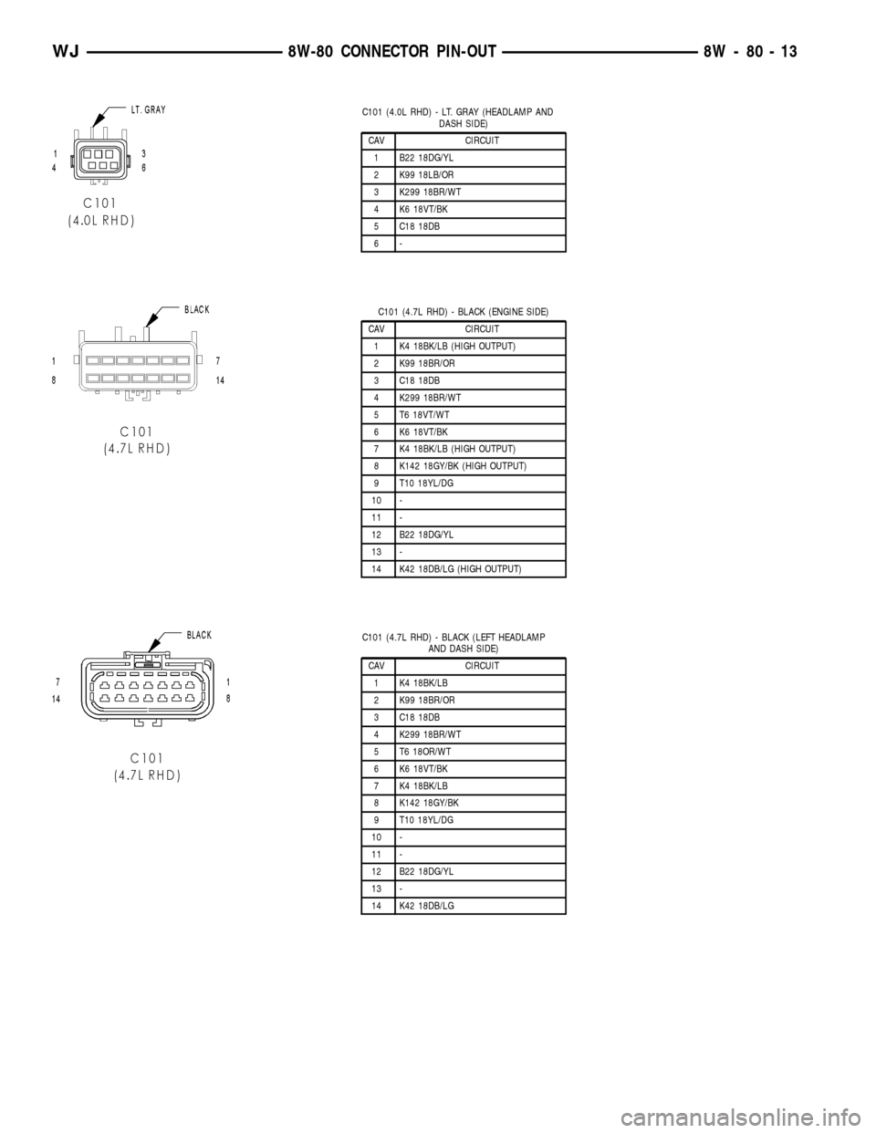
C101 (4.0L RHD) - LT. GRAY (HEADLAMP AND
DASH SIDE)
CAV CIRCUIT
1 B22 18DG/YL
2 K99 18LB/OR
3 K299 18BR/WT
4 K6 18VT/BK
5 C18 18DB
6-
C101 (4.7L RHD) - BLACK (ENGINE SIDE)
CAV CIRCUIT
1 K4 18BK/LB (HIGH OUTPUT)
2 K99 18BR/OR
3 C18 18DB
4 K299 18BR/WT
5 T6 18VT/WT
6 K6 18VT/BK
7 K4 18BK/LB (HIGH OUTPUT)
8 K142 18GY/BK (HIGH OUTPUT)
9 T10 18YL/DG
10 -
11 -
12 B22 18DG/YL
13 -
14 K42 18DB/LG (HIGH OUTPUT)
C101 (4.7L RHD) - BLACK (LEFT HEADLAMP
AND DASH SIDE)
CAV CIRCUIT
1 K4 18BK/LB
2 K99 18BR/OR
3 C18 18DB
4 K299 18BR/WT
5 T6 18OR/WT
6 K6 18VT/BK
7 K4 18BK/LB
8 K142 18GY/BK
9 T10 18YL/DG
10 -
11 -
12 B22 18DG/YL
13 -
14 K42 18DB/LG
WJ8W-80 CONNECTOR PIN-OUT 8W - 80 - 13
Page 1061 of 2199

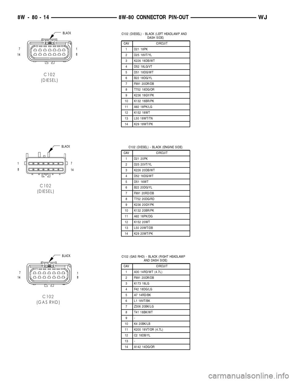
C102 (DIESEL) - BLACK (LEFT HEADLAMP AND
DASH SIDE)
CAV CIRCUIT
1 D21 18PK
2 D25 18VT/YL
3 K226 18DB/WT
4 D52 18LG/VT
5 D51 18DG/WT
6 B22 18DG/YL
7 F991 20OR/DB
8 T752 18DG/OR
9 K236 18GY/PK
10 K132 18BR/PK
11 A82 18PK/LG
12 K152 18WT
13 L50 18WT/TN
14 K29 18WT/PK
C102 (DIESEL) - BLACK (ENGINE SIDE)
CAV CIRCUIT
1 D21 20PK
2 D25 20VT/YL
3 K226 20DB/WT
4 D52 16DG/WT
5 D51 16WT
6 B22 20DG/YL
7 F991 20RD/DB
8 T752 20DG/RD
9 K236 20GY/PK
10 K132 20BR/PK
11 A82 16PK/DG
12 K152 20WT
13 L50 20WT/DB
14 K29 20WT/PK
C102 (GAS RHD) - BLACK (RIGHT HEADLAMP
AND DASH SIDE)
CAV CIRCUIT
1 A30 14RD/WT (4.7L)
2 F991 20OR/DB
3 K173 18LG
4 F42 18DG/LG
5 A7 14RD/BK
6 L1 18VT/BK
7 Z306 20BK/LG
8 T41 18BK/WT
9-
10 K4 20BK/LB
11 K200 18VT/OR (4.7L)
12 C2 18DB/YL
13 -
14 A142 14DG/OR
8W - 80 - 14 8W-80 CONNECTOR PIN-OUTWJ
Page 1062 of 2199

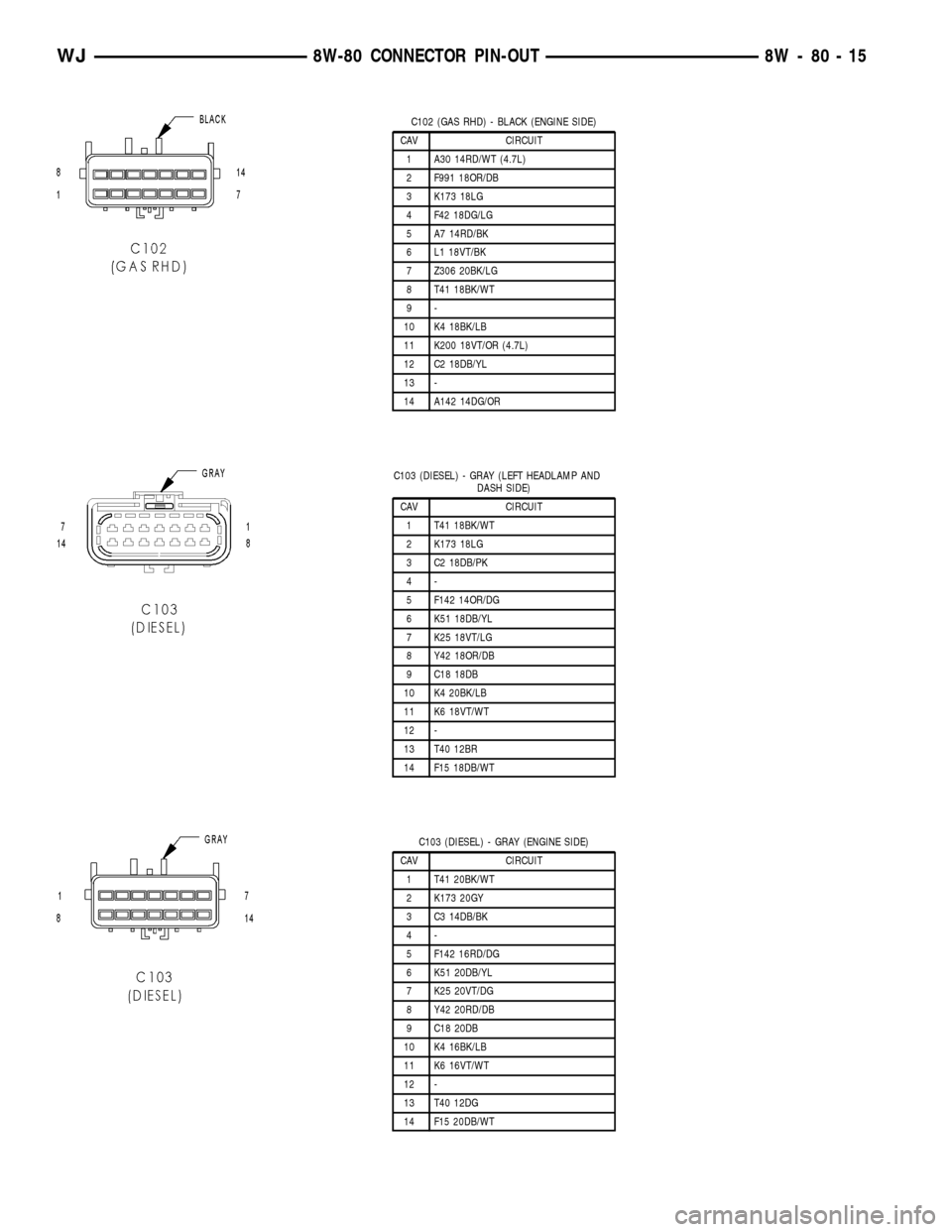
C102 (GAS RHD) - BLACK (ENGINE SIDE)
CAV CIRCUIT
1 A30 14RD/WT (4.7L)
2 F991 18OR/DB
3 K173 18LG
4 F42 18DG/LG
5 A7 14RD/BK
6 L1 18VT/BK
7 Z306 20BK/LG
8 T41 18BK/WT
9-
10 K4 18BK/LB
11 K200 18VT/OR (4.7L)
12 C2 18DB/YL
13 -
14 A142 14DG/OR
C103 (DIESEL) - GRAY (LEFT HEADLAMP AND
DASH SIDE)
CAV CIRCUIT
1 T41 18BK/WT
2 K173 18LG
3 C2 18DB/PK
4-
5 F142 14OR/DG
6 K51 18DB/YL
7 K25 18VT/LG
8 Y42 18OR/DB
9 C18 18DB
10 K4 20BK/LB
11 K6 18VT/WT
12 -
13 T40 12BR
14 F15 18DB/WT
C103 (DIESEL) - GRAY (ENGINE SIDE)
CAV CIRCUIT
1 T41 20BK/WT
2 K173 20GY
3 C3 14DB/BK
4-
5 F142 16RD/DG
6 K51 20DB/YL
7 K25 20VT/DG
8 Y42 20RD/DB
9 C18 20DB
10 K4 16BK/LB
11 K6 16VT/WT
12 -
13 T40 12DG
14 F15 20DB/WT
WJ8W-80 CONNECTOR PIN-OUT 8W - 80 - 15