service indicator JEEP GRAND CHEROKEE 2003 WJ / 2.G Manual PDF
[x] Cancel search | Manufacturer: JEEP, Model Year: 2003, Model line: GRAND CHEROKEE, Model: JEEP GRAND CHEROKEE 2003 WJ / 2.GPages: 2199, PDF Size: 76.01 MB
Page 1871 of 2199

TIRE PRESSURE MONITORING
DESCRIPTION
The EVIC will monitor the tire pressure signals
from the five tire sensors and determine if any tire
has gone below the low pressure threshold or raised
above the high pressure threshold. Refer to the table
below.
LOW TIRE PRESSURE THRESHOLDS
SYSTEM STATUS
INDICATORTIRE PRESSURE
ON 179 kPa (26 PSI)
OFF 214 kPa (31 PSI)
HIGH TIRE PRESSURE THRESHOLDS
SYSTEM STATUS
INDICATORTIRE PRESSURE
ON 310 kPa (45 PSI)
OFF 276 kPa (40 PSI)
The Remote Tire Pressure Monitors (RTPM) are
not internally serviceable. For a Sensor Failure or
Low Battery fault, the RTPM must be replaced.
OPERATION
If equipped with the Tire Pressure Monitoring Sys-
tem, each of the vehicle's five wheels will have a
valve stem with a pressure sensor and radio trans-
mitter built in. Signals from the tire pressure sensors
are received and interpreted by the Electronic Vehi-
cle Information Center (EVIC). A sensor in a
mounted wheel will broadcast its detected pressure
once per minute when the vehicle is moving faster
than 40 km/h (25 mph). The spare tire sensor will
broadcast once every hour. Each sensor's broadcast is
uniquely coded so that the EVIC can determine loca-
tion. The individual tire pressures can be displayed
graphically on the EVIC
DIAGNOSIS AND TESTING - TIRE PRESSURE
MONITORING SYSTEM
All Tire Pressure Monitoring System Faults are
specific to one location. If a9BATTERY LOW9or
9SENSOR FAILURE9fault is detected, the location
will be displayed. The appropriate sensor/transmitter
can then be replaced. If a single sensor/transmitter
cannot be detected by the EVIC, replace that sensor
transmitter. If none of the sensors/transmitters can
be detected, refer to symptoms in the EVIC section.
For additional system description and diagnosis,
refer to Tire Pressure Monitoring in the Body Diag-
nostic manual.
SENSOR
REMOVAL - TIRE PRESSURE SENSOR/
TRANSMITTER
(1) Remove the tire/wheel from the vehicle.
CAUTION: When removing the stick on balancing
weights from the wheel, do not use an abrasive
cleaner or a cleaner which will damage the protec-
tive finish on the wheel.
(2) Remove the balancing weights from the wheel.
NOTE: The cap used on this valve stem contains an
O-ring seal to prevent contamination and moisture
from entering the valve stem. Retain this valve stem
cap for re-use. Do not substitute a regular valve
stem cap in its place.
(3) Remove the cap from the valve stem.
NOTE: The valve stem used on this vehicle is made
of aluminum and the core is nickel plated brass.
The original valve stem core must be reinstalled
and not substituted for a valve stem core made of a
different material. This is required to prevent corro-
sion in the valve stem caused by the different met-
als.
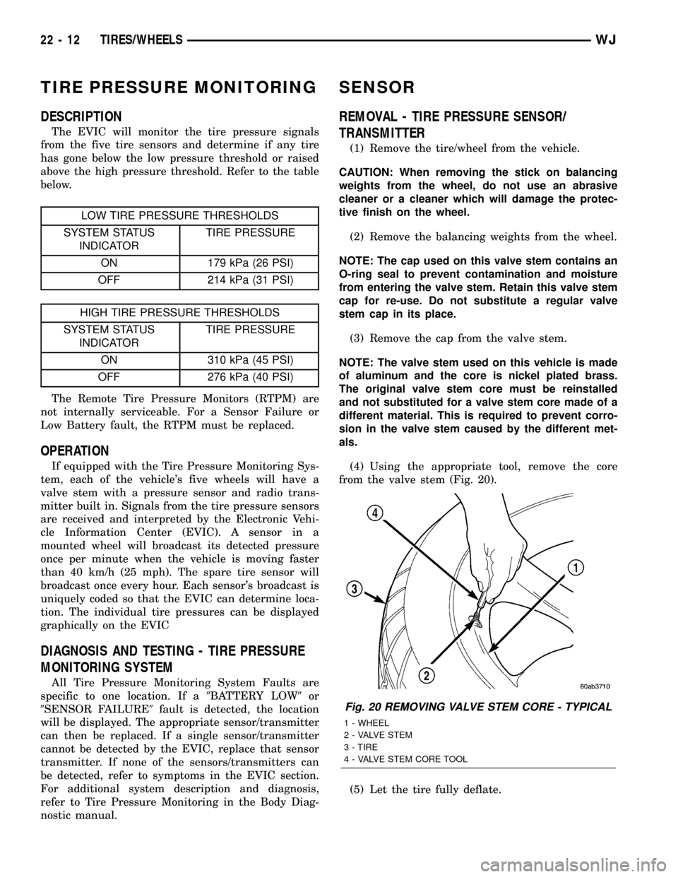
(4) Using the appropriate tool, remove the core
from the valve stem (Fig. 20).
(5) Let the tire fully deflate.
Fig. 20 REMOVING VALVE STEM CORE - TYPICAL
1 - WHEEL
2 - VALVE STEM
3 - TIRE
4 - VALVE STEM CORE TOOL
22 - 12 TIRES/WHEELSWJ
Page 1925 of 2199

INSTALLATION
WARNING: ON VEHICLES EQUIPPED WITH AIR-
BAGS, DISABLE THE AIRBAG SYSTEM BEFORE
ATTEMPTING ANY STEERING WHEEL, STEERING
COLUMN, OR INSTRUMENT PANEL COMPONENT
DIAGNOSIS OR SERVICE. DISCONNECT AND ISO-
LATE THE BATTERY NEGATIVE (GROUND) CABLE,
THEN WAIT TWO MINUTES FOR THE AIRBAG SYS-
TEM CAPACITOR TO DISCHARGE BEFORE PER-
FORMING FURTHER DIAGNOSIS OR SERVICE. THIS
IS THE ONLY SURE WAY TO DISABLE THE AIRBAG
SYSTEM. FAILURE TO TAKE THE PROPER PRE-
CAUTIONS COULD RESULT IN ACCIDENTAL AIR-
BAG DEPLOYMENT AND POSSIBLE PERSONAL
INJURY.
(1) If the vehicle is not equipped with the optional
automatic headlamps light sensor/vehicle theft secu-
rity system indicator, be certain that the hole plug is
installed in the clearance hole located to the out-
board side of the driver side defroster outlet in the
instrument panel top cover (Fig. 22).
(2) Before installing the top cover onto the top of
the instrument panel, be certain that the rubber top
cover seal is properly positioned on the forward edge
of the top cover panel.
(3) Position the top cover onto the top of the
instrument panel.
(4) Align the four snap clips on the top cover with
the snap clip receptacles in the instrument panel top
pad.
(5) Press firmly downward on the top cover over
each of the four snap clip locations until each of the
snap clips is fully seated in their receptacles in the
instrument panel top pad.
(6) Reconnect the battery negative cable.
INSTRUMENT PANEL TOP PAD
REMOVAL
WARNING: ON VEHICLES EQUIPPED WITH AIR-
BAGS, DISABLE THE AIRBAG SYSTEM BEFORE
ATTEMPTING ANY STEERING WHEEL, STEERING
COLUMN, OR INSTRUMENT PANEL COMPONENT
DIAGNOSIS OR SERVICE. DISCONNECT AND ISO-
LATE THE BATTERY NEGATIVE (GROUND) CABLE,
THEN WAIT TWO MINUTES FOR THE AIRBAG SYS-
TEM CAPACITOR TO DISCHARGE BEFORE PER-
FORMING FURTHER DIAGNOSIS OR SERVICE. THIS
IS THE ONLY SURE WAY TO DISABLE THE AIRBAG
SYSTEM. FAILURE TO TAKE THE PROPER PRE-
CAUTIONS COULD RESULT IN ACCIDENTAL AIR-
BAG DEPLOYMENT AND POSSIBLE PERSONAL
INJURY.(1) Disconnect and isolate the battery negative
cable.
(2) Remove the trim from the right and left A-pil-
lars. (Refer to 23 - BODY/INTERIOR/A-PILLAR
TRIM - REMOVAL).
(3) Remove the top cover from the instrument
panel. (Refer to 23 - BODY/INSTRUMENT PANEL/
INSTRUMENT PANEL TOP COVER - REMOVAL).
(4) Remove the four nuts that secure the instru-
ment panel top pad to the studs on the dash panel
near the windshield fence line (Fig. 23).
(5) Remove the speakers from the instrument
panel top pad. (Refer to 8 - ELECTRICAL/AUDIO/
SPEAKER - REMOVAL - INSTRUMENT PANEL
SPEAKER).
(6) Disengage the retainer that secures each of the
two instrument panel wire harness speaker take outs
to the mounting hole in the instrument panel top
pad. Tuck the loose ends of these speaker take outs
down the defroster ducts to keep them out of the way
during the remainder of this procedure.
(7) If the vehicle is so equipped, remove the two
screws that secure the automatic headlamp light sen-
sor/vehicle theft security system indicator unit to the
instrument panel top pad just outboard of the driver
side defroster outlet. Move the sensor/indicator unit
towards the windshield to keep it out of the way dur-
ing the remainder of this procedure.
(8) Remove the cluster bezel from the instrument
panel. (Refer to 23 - BODY/INSTRUMENT PANEL/
CLUSTER BEZEL - REMOVAL).
(9) Remove the instrument cluster from the instru-
ment panel. (Refer to 8 - ELECTRICAL/INSTRU-
MENT CLUSTER - REMOVAL).
(10) Remove the steering column opening cover
from the instrument panel. (Refer to 23 - BODY/IN-
STRUMENT PANEL/STEERING COLUMN OPEN-
ING COVER - REMOVAL).
(11) Roll the glove box down from the instrument
panel. (Refer to 23 - BODY/INSTRUMENT PANEL/
GLOVE BOX - STANDARD PROCEDURE - GLOVE
BOX ROLL DOWN).
(12) Remove the end cap from the passenger side
lower outboard end of the instrument panel. (Refer to
23 - BODY/INSTRUMENT PANEL/INSTRUMENT
PANEL END CAP - REMOVAL).
(13) Remove the lower right center bezel from the
instrument panel. (Refer to 23 - BODY/INSTRU-
MENT PANEL/IP LOWER RIGHT CENTER BEZEL
- REMOVAL).
(14) Remove the glove box lamp and switch from
the instrument panel. (Refer to 8 - ELECTRICAL/
LAMPS/LIGHTING - INTERIOR/GLOVE BOX
LAMP/SWITCH - REMOVAL).
23 - 52 INSTRUMENT PANEL SYSTEMWJ
INSTRUMENT PANEL TOP COVER (Continued)
Page 2170 of 2199

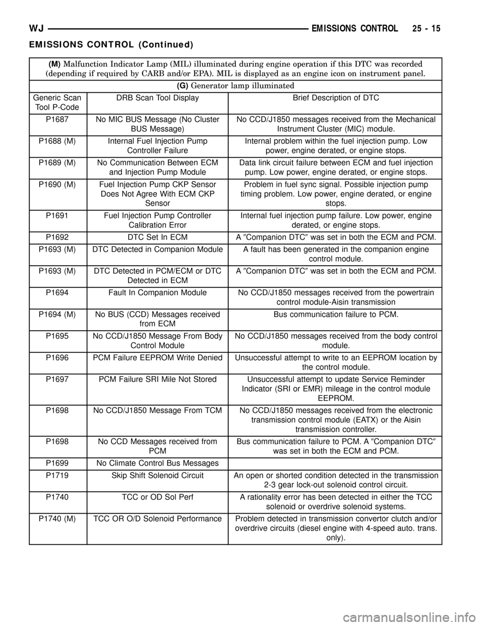
(M)Malfunction Indicator Lamp (MIL) illuminated during engine operation if this DTC was recorded
(depending if required by CARB and/or EPA). MIL is displayed as an engine icon on instrument panel.
(G)Generator lamp illuminated
Generic Scan
Tool P-CodeDRB Scan Tool Display Brief Description of DTC
P1687 No MIC BUS Message (No Cluster
BUS Message)No CCD/J1850 messages received from the Mechanical
Instrument Cluster (MIC) module.
P1688 (M) Internal Fuel Injection Pump
Controller FailureInternal problem within the fuel injection pump. Low
power, engine derated, or engine stops.
P1689 (M) No Communication Between ECM
and Injection Pump ModuleData link circuit failure between ECM and fuel injection
pump. Low power, engine derated, or engine stops.
P1690 (M) Fuel Injection Pump CKP Sensor
Does Not Agree With ECM CKP
SensorProblem in fuel sync signal. Possible injection pump
timing problem. Low power, engine derated, or engine
stops.
P1691 Fuel Injection Pump Controller
Calibration ErrorInternal fuel injection pump failure. Low power, engine
derated, or engine stops.
P1692 DTC Set In ECM A9Companion DTC9was set in both the ECM and PCM.
P1693 (M) DTC Detected in Companion Module A fault has been generated in the companion engine
control module.
P1693 (M) DTC Detected in PCM/ECM or DTC
Detected in ECMA9Companion DTC9was set in both the ECM and PCM.
P1694 Fault In Companion Module No CCD/J1850 messages received from the powertrain
control module-Aisin transmission
P1694 (M) No BUS (CCD) Messages received
from ECMBus communication failure to PCM.
P1695 No CCD/J1850 Message From Body
Control ModuleNo CCD/J1850 messages received from the body control
module.
P1696 PCM Failure EEPROM Write Denied Unsuccessful attempt to write to an EEPROM location by
the control module.
P1697 PCM Failure SRI Mile Not Stored Unsuccessful attempt to update Service Reminder
Indicator (SRI or EMR) mileage in the control module
EEPROM.
P1698 No CCD/J1850 Message From TCM No CCD/J1850 messages received from the electronic
transmission control module (EATX) or the Aisin
transmission controller.
P1698 No CCD Messages received from
PCMBus communication failure to PCM. A9Companion DTC9
was set in both the ECM and PCM.
P1699 No Climate Control Bus Messages
P1719 Skip Shift Solenoid Circuit An open or shorted condition detected in the transmission
2-3 gear lock-out solenoid control circuit.
P1740 TCC or OD Sol Perf A rationality error has been detected in either the TCC
solenoid or overdrive solenoid systems.
P1740 (M) TCC OR O/D Solenoid Performance Problem detected in transmission convertor clutch and/or
overdrive circuits (diesel engine with 4-speed auto. trans.
only).
WJEMISSIONS CONTROL 25 - 15
EMISSIONS CONTROL (Continued)