tail light wiring JEEP GRAND CHEROKEE 2003 WJ / 2.G Workshop Manual
[x] Cancel search | Manufacturer: JEEP, Model Year: 2003, Model line: GRAND CHEROKEE, Model: JEEP GRAND CHEROKEE 2003 WJ / 2.GPages: 2199, PDF Size: 76.01 MB
Page 395 of 2199
HORN SWITCH
DESCRIPTION
A center-blow, normally open, resistive membrane-
type horn switch is secured in a plastic tray that is
inserted in a pocket sewn on the front of the driver
side airbag retainer strap. The horn switch is con-
cealed behind the driver side airbag module trim
cover in the center of the steering wheel. The switch
consists of two plastic membranes, one that is flat
and one that is slightly convex. These two mem-
branes are secured to each other around the perime-
ter. Inside the switch, the centers of the facing
surfaces of these membranes each has a grid made
with an electrically conductive material applied to it.
One of the grids is connected to a circuit that pro-
vides it with continuity to ground at all times. The
grid of the other membrane is connected to the horn
relay control circuit.
The steering wheel and steering column must be
properly grounded in order for the horn switch to
function properly. The horn switch and plastic tray
are serviced as a unit. If the horn switch is damaged
or faulty, or if the driver side airbag is deployed, the
horn switch and tray must be replaced as a unit.
OPERATION
When the center area of the driver side airbag trim
cover is depressed, the electrically conductive grids
on the facing surfaces of the horn switch membranes
contact each other, closing the switch circuit. The
completed horn switch circuit provides a ground for
the control coil side of the horn relay, which activates
the relay. When the horn switch is released, the
resistive tension of the convex membrane separates
the two electrically conductive grids and opens the
switch circuit.
DIAGNOSIS AND TESTING - HORN SWITCH
For complete circuit diagrams, refer to the appro-
priate wiring information. The wiring information
includes wiring diagrams, proper wire and connector
repair procedures, details of wire harness routing
and retention, connector pin-out information and
location views for the various wire harness connec-
tors, splices and grounds.
WARNING: ON VEHICLES EQUIPPED WITH AIR-
BAGS, REFER TO ELECTRICAL, RESTRAINTS
BEFORE ATTEMPTING ANY STEERING WHEEL,
STEERING COLUMN, OR INSTRUMENT PANEL
COMPONENT DIAGNOSIS OR SERVICE. FAILURE
TO TAKE THE PROPER PRECAUTIONS COULD
RESULT IN ACCIDENTAL AIRBAG DEPLOYMENT
AND POSSIBLE PERSONAL INJURY.
(1) Disconnect and isolate the battery negative
cable. Remove the steering column opening cover
from the instrument panel.
(2) Check for continuity between the metal steer-
ing column jacket and a good ground. There should
be continuity. If OK, go to Step 3. If not OK, refer to
Steering, Column for proper installation of the steer-
ing column.
(3) Remove the driver side airbag module from the
steering wheel. Disconnect the horn switch wire har-
ness connectors from the driver side airbag module.
(4) Remove the horn relay from the Power Distri-
bution Center (PDC). Check for continuity between
the steering column half of the horn switch feed wire
harness connector and a good ground. There should
be no continuity. If OK, go to Step 5. If not OK,
repair the shorted horn relay control circuit to the
horn relay in the PDC as required.
(5) Check for continuity between the steering col-
umn half of the horn switch feed wire harness con-
nector and the horn relay control circuit cavity for
the horn relay in the PDC. There should be continu-
ity. If OK, go to Step 6. If not OK, repair the open
horn relay control circuit to the horn relay in the
PDC as required.
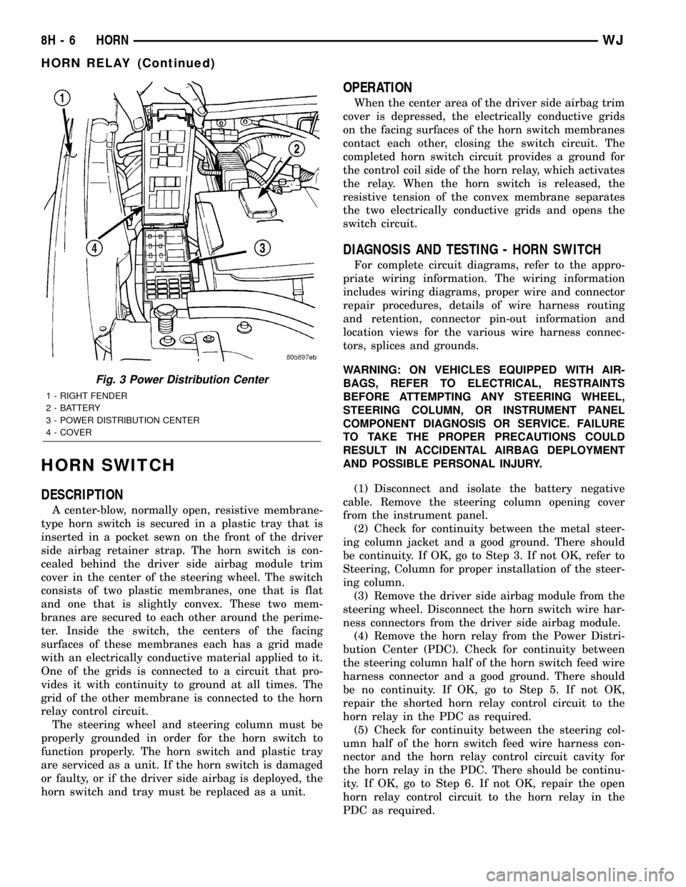
Fig. 3 Power Distribution Center
1 - RIGHT FENDER
2 - BATTERY
3 - POWER DISTRIBUTION CENTER
4 - COVER
8H - 6 HORNWJ
HORN RELAY (Continued)
Page 412 of 2199
INSTALLATION
4.7L High-Output Engine Only
NOTE: The left sensor is identified by an identifica-
tion tag (LEFT). It is also identified by a larger bolt
head. The Powertrain Control Module (PCM) must
have and know the correct sensor left/right posi-
tions. Do not mix the sensor locations.
(1) Thoroughly clean knock sensor mounting holes.
(2) Install sensors (Fig. 22) into cylinder block.
NOTE: Over or under tightening the sensor mount-
ing bolts will affect knock sensor performance, pos-
sibly causing improper spark control. Always use
the specified torque when installing the knock sen-
sors. The torque for the knock senor bolt is rela-
tively light for an 8mm bolt.
NOTE: Note foam strip on bolt threads. This foam is
used only to retain the bolts to sensors for plant
assembly. It is not used as a sealant. Do not apply
any adhesive, sealant or thread locking compound
to these bolts.
(3) Install and tighten mounting bolts.Bolt
torque is critical.Refer to torque specification.
(4) Install intake manifold. Refer to Engine sec-
tion.
(5) Connect knock sensor pigtail wiring harness to
engine wiring harness near right / rear of intake
manifold (Fig. 23).
SPARK PLUG
DESCRIPTION
Both the 4.0L 6-cylinder and the 4.7L V-8 engine
use resistor type spark plugs. Standard 4.7L V-8
engines are equipped with ªfired in suppressor sealº
type spark plugs using a copper core ground elec-
trode. High-Output (H.O.) 4.7L V-8 engines are
equipped with unique plugs using a platinum rivet
located on the tip of the center electrode.
Because of the use of an aluminum cylinder head
on the 4.7L engine, spark plug torque is very critical.
To prevent possible pre-ignition and/or mechanical
engine damage, the correct type/heat range/number
spark plug must be used.Do not substitute any
other spark plug on the 4.7L H.O. engine. Seri-
ous engine damage may occur.
Plugs on both engines have resistance values rang-
ing from 6,000 to 20,000 ohms (when checked with at
least a 1000 volt spark plug tester).Do not use an
ohmmeter to check the resistance values of thespark plugs. Inaccurate readings will result.
Remove the spark plugs and examine them for
burned electrodes and fouled, cracked or broken por-
celain insulators. Keep plugs arranged in the order
in which they were removed from the engine. A sin-
gle plug displaying an abnormal condition indicates
that a problem exists in the corresponding cylinder.
Replace spark plugs at the intervals recommended in
Group O, Lubrication and Maintenance.
EXCEPT 4.7L H.O. ENGINE :Spark plugs that
have low mileage may be cleaned and reused if not
otherwise defective, carbon or oil fouled. Also refer to
Spark Plug Conditions.4.7L H.O. ENGINE :Never
clean spark plugs on the 4.7L H.O. engine. Damage
to the platinum rivet will result.
CAUTION: EXCEPT 4.7L H.O. ENGINE : Never use a
motorized wire wheel brush to clean the spark
plugs. Metallic deposits will remain on the spark
plug insulator and will cause plug misfire.
H.O. Gap Adjustment:If equipped with the 4.7L
H.O. engine, do not use a wire-type gapping tool as
damage to the platinum rivet on the center electrode
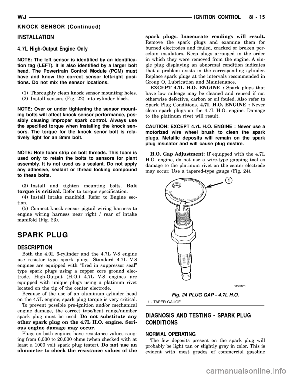
may occur. Use a tapered-type gauge (Fig. 24).
DIAGNOSIS AND TESTING - SPARK PLUG
CONDITIONS
NORMAL OPERATING
The few deposits present on the spark plug will
probably be light tan or slightly gray in color. This is
evident with most grades of commercial gasoline
Fig. 24 PLUG GAP - 4.7L H.O.
1 - TAPER GAUGE
WJIGNITION CONTROL 8I - 15
KNOCK SENSOR (Continued)
Page 418 of 2199
EMIC also uses several hard wired inputs in order to
perform its many functions. The EMIC module incor-
porates a blue-green digital Vacuum Fluorescent Dis-
play (VFD) for displaying odometer and trip
odometer information.
The EMIC houses six analog gauges and has pro-
visions for up to twenty indicators (Fig. 2). The
EMIC includes the following analog gauges:
²Coolant Temperature Gauge
²Fuel Gauge
²Oil Pressure Gauge
²Speedometer
²Tachometer
²Voltage Gauge
Some of the EMIC indicators are automatically
configured when the EMIC is connected to the vehi-
cle electrical system for compatibility with certain
optional equipment or equipment required for regula-
tory purposes in certain markets. While each EMIC
may have provisions for indicators to support every
available option, the configurable indicators will not
be functional in a vehicle that does not have the
equipment that an indicator supports. The EMIC
includes provisions for the following indicators (Fig.
2):
²Airbag Indicator (with Airbags only)
²Antilock Brake System (ABS) Indicator
²Brake Indicator
²Check Gauges Indicator
²Coolant Low Indicator (with Diesel Engine
only)
²Cruise Indicator
²Four-Wheel Drive Part Time Indicator
(with Selec-Trac NVG-242 Transfer Case only)
²Front Fog Lamp Indicator (with Front Fog
Lamps only)
²High Beam Indicator
²Low Fuel Indicator
²Malfunction Indicator Lamp (MIL)
²Overdrive-Off Indicator (except Diesel
Engine)
²Rear Fog Lamp Indicator (with Rear Fog
Lamps only)
²Seatbelt Indicator
²Sentry Key Immobilizer System (SKIS)
Indicator
²Transmission Overtemp Indicator (except
Diesel Engine)²Turn Signal (Right and Left) Indicators
²Wait-To-Start Indicator (with Diesel Engine
only)
²Water-In-Fuel Indicator (with Diesel Engine
only)
Many indicators in the EMIC are illuminated by a
dedicated Light Emitting Diode (LED) that is sol-
dered onto the EMIC electronic circuit board. The
LEDs are not available for service replacement and,
if damaged or faulty, the entire EMIC must be
replaced. Base cluster illumination is accomplished
by dimmable incandescent back lighting, which illu-
minates the gauges for visibility when the exterior
lighting is turned on. Premium cluster illumination
is accomplished by a dimmable electro-luminescent
lamp that is serviced only as a unit with the EMIC.
Each of the incandescent bulbs is secured by an inte-
gral bulb holder to the electronic circuit board from
the back of the cluster housing. The incandescent
bulb/bulb holder units are available for service
replacement.
Hard wired circuitry connects the EMIC to the
electrical system of the vehicle. These hard wired cir-
cuits are integral to several wire harnesses, which
are routed throughout the vehicle and retained by
many different methods. These circuits may be con-
nected to each other, to the vehicle electrical system
and to the EMIC through the use of a combination of
soldered splices, splice block connectors, and many
different types of wire harness terminal connectors
and insulators. Refer to the appropriate wiring infor-
mation. The wiring information includes wiring dia-
grams, proper wire and connector repair procedures,
further details on wire harness routing and reten-
tion, as well as pin-out and location views for the
various wire harness connectors, splices and grounds.
The EMIC modules for this model are serviced only
as complete units. The EMIC module cannot be
adjusted or repaired. If a gauge, an LED indicator,
the VFD, the electronic circuit board, the circuit
board hardware, the cluster overlay, the electro-lumi-
nescent lamp (premium model only) or the EMIC
housing are damaged or faulty, the entire EMIC mod-
ule must be replaced. The cluster lens, hood and
mask unit and the individual incandescent lamp
bulbs with holders are available for service replace-
ment.
WJINSTRUMENT CLUSTER 8J - 3
INSTRUMENT CLUSTER (Continued)
Page 422 of 2199
an input from the auto headlamp light sensor to
determine the ambient light levels. If the BCM
decides that the exterior lighting is turned on in the
daylight, it overrides the selected panel dimmer
switch signal by sending a message over the PCI
data bus to illuminate all vacuum fluorescent dis-
plays at full brightness for improved visibility in day-
time light levels. The automatic parade mode has no
effect on the incandescent bulb illumination intensity.
The hard wired cluster illumination circuits
between the left (lighting) multi-function switch and
the BCM may be diagnosed using conventional diag-
nostic tools and methods. The electro-luminescent
lamp is diagnosed using the EMIC self-diagnostic
actuator test. (Refer to 8 - ELECTRICAL/INSTRU-
MENT CLUSTER - DIAGNOSIS AND TESTING).
However, proper testing of the EMIC and the elec-
tronic dimming level messages sent by the BCM over
the PCI data bus requires the use of a DRBIIItscan
tool. Refer to the appropriate diagnostic information.
CHIME SERVICE
The EMIC is programmed to request chime service
from the Body Control Module (BCM) when certain
indicators are illuminated. The EMIC chime request
for illumination of the low fuel indicator is a cus-
tomer programmable feature. When the programmed
conditions are met, the EMIC generates an electronic
chime request message and sends it over the PCI
data bus to the BCM. Upon receiving the proper
chime request, the BCM activates an integral chime
tone generator to provide the audible chime tone to
the vehicle operator. (Refer to 8 - ELECTRICAL/
CHIME WARNING SYSTEM - OPERATION). Proper
testing of the PCI data bus and the electronic chime
request message outputs from the EMIC requires the
use of a DRBIIItscan tool. Refer to the appropriate
diagnostic information.
DIAGNOSIS AND TESTING - INSTRUMENT
CLUSTER
If all of the instrument cluster gauges and/or indi-
cators are inoperative, refer to PRELIMINARY
DIAGNOSIS . If an individual gauge or Programma-
ble Communications Interface (PCI) data bus mes-
sage-controlled indicator is inoperative, refer to
ACTUATOR TEST . If an individual hard wired indi-
cator is inoperative, refer to the diagnosis and testing
information for that specific indicator. If the base
instrument cluster incandescent illumination lighting
is inoperative, refer to CLUSTER ILLUMINATION
DIAGNOSIS . If the premium instrument cluster
electro-luminescent illumination lighting is inopera-
tive, refer to ACTUATOR TEST . Refer to the appro-
priate wiring information. The wiring information
includes wiring diagrams, proper wire and connectorrepair procedures, details of wire harness routing
and retention, connector pin-out information and
location views for the various wire harness connec-
tors, splices and grounds.
NOTE: Occasionally, a condition may be encoun-
tered where the gauge pointer for the speedometer
or the tachometer becomes caught on the wrong
side of the pointer stop. To correct this condition,
the technician should use a DRBIIITscan tool and
the appropriate diagnostic information to perform
the instrument cluster self-diagnostic actuator test
procedure. When performed, the actuator test pro-
cedure will automatically return the pointer to the
correct side of the pointer stop.
PRELIMINARY DIAGNOSIS
WARNING: ON VEHICLES EQUIPPED WITH AIR-
BAGS, DISABLE THE SUPPLEMENTAL RESTRAINT
SYSTEM BEFORE ATTEMPTING ANY STEERING
WHEEL, STEERING COLUMN, DRIVER AIRBAG,
PASSENGER AIRBAG, SIDE CURTAIN AIRBAG,
FRONT IMPACT SENSOR, SIDE IMPACT SENSOR,
OR INSTRUMENT PANEL COMPONENT DIAGNOSIS
OR SERVICE. DISCONNECT AND ISOLATE THE
BATTERY NEGATIVE (GROUND) CABLE, THEN
WAIT TWO MINUTES FOR THE SYSTEM CAPACI-
TOR TO DISCHARGE BEFORE PERFORMING FUR-
THER DIAGNOSIS OR SERVICE. THIS IS THE ONLY
SURE WAY TO DISABLE THE SUPPLEMENTAL
RESTRAINT SYSTEM. FAILURE TO TAKE THE
PROPER PRECAUTIONS COULD RESULT IN ACCI-
DENTAL AIRBAG DEPLOYMENT AND POSSIBLE
PERSONAL INJURY.
WARNING: ON VEHICLES EQUIPPED WITH THE
PREMIUM INSTRUMENT CLUSTER, THE CLUSTER
CIRCUITRY PROVIDES AN ALTERNATING CURRENT
TO SUPPLY POWER TO THE ELECTRO-LUMINES-
CENT ILLUMINATION LAMP THROUGH A PIGTAIL
WIRE AND CONNECTOR THAT IS ACCESSIBLE AT
THE BACK OF THE CLUSTER HOUSING. USE
PROPER PRECAUTIONS WHEN HANDLING THIS
UNIT DURING DIAGNOSIS OR SERVICE TO AVOID
ELECTRICAL SHOCK AND POSSIBLE PERSONAL
INJURY.
(1) Check the fused B(+) fuse (Fuse 17 - 10
ampere) in the Junction Block (JB). If OK, go to Step
2. If not OK, repair the shorted circuit or component
as required and replace the faulty fuse.
(2) Check for battery voltage at the fused B(+) fuse
(Fuse 17 - 10 ampere) in the JB. If OK, go to Step 3.
If not OK, repair the open fused B(+) circuit between
WJINSTRUMENT CLUSTER 8J - 7
INSTRUMENT CLUSTER (Continued)
Page 431 of 2199
For further diagnosis of the brake indicator or the
instrument cluster circuitry that controls the indica-
tor, (Refer to 8 - ELECTRICAL/INSTRUMENT
CLUSTER - DIAGNOSIS AND TESTING). The park
brake switch input to the instrument cluster can be
diagnosed using conventional diagnostic tools and
methods. For proper diagnosis of the brake fluid level
switch input to the CAB, the anti-lock brake system,
the CAB, the PCI data bus, or the electronic message
inputs to the instrument cluster that control the
brake indicator, a DRBIIItscan tool is required.
Refer to the appropriate diagnostic information.
DIAGNOSIS AND TESTING - BRAKE INDICATOR
The diagnosis found here addresses an inoperative
park brake indicator condition. If there are problems
with several indicators in the instrument cluster,
(Refer to 8 - ELECTRICAL/INSTRUMENT CLUS-
TER - DIAGNOSIS AND TESTING). If the brake
indicator stays on with the ignition switch in the On
position and the park brake released, or comes on
while driving, (Refer to 5 - BRAKES - DIAGNOSIS
AND TESTING). If no brake system problem is
found, the following procedures will help to locate a
shorted or open circuit, or a faulty park brake switch
input. Refer to the appropriate wiring information.
The wiring information includes wiring diagrams,
proper wire and connector repair procedures, details
of wire harness routing and retention, connector pin-
out information and location views for the various
wire harness connectors, splices and grounds.
WARNING: ON VEHICLES EQUIPPED WITH AIR-
BAGS, DISABLE THE SUPPLEMENTAL RESTRAINT
SYSTEM BEFORE ATTEMPTING ANY STEERING
WHEEL, STEERING COLUMN, DRIVER AIRBAG,
PASSENGER AIRBAG, SIDE CURTAIN AIRBAG,
FRONT IMPACT SENSOR, SIDE IMPACT SENSOR,
OR INSTRUMENT PANEL COMPONENT DIAGNOSIS
OR SERVICE. DISCONNECT AND ISOLATE THE
BATTERY NEGATIVE (GROUND) CABLE, THEN
WAIT TWO MINUTES FOR THE SYSTEM CAPACI-
TOR TO DISCHARGE BEFORE PERFORMING FUR-
THER DIAGNOSIS OR SERVICE. THIS IS THE ONLY
SURE WAY TO DISABLE THE SUPPLEMENTAL
RESTRAINT SYSTEM. FAILURE TO TAKE THE
PROPER PRECAUTIONS COULD RESULT IN ACCI-
DENTAL AIRBAG DEPLOYMENT AND POSSIBLE
PERSONAL INJURY.
INDICATOR ILLUMINATES DURING BULB TEST, BUT DOES
NOT WHEN PARK BRAKE APPLIED
(1) Disconnect and isolate the battery negative
cable. Disconnect the instrument panel wire harness
connector for the park brake switch from the switch
terminal. Apply the parking brake. Check for conti-nuity between the park brake switch terminal and a
good ground. There should be continuity. If OK, go to
Step 2. If not OK, replace the faulty park brake
switch.
(2) Disconnect the instrument panel wire harness
connector for the instrument cluster from the cluster
connector receptacle. Check for continuity between
the red brake warning indicator driver circuit cavi-
ties of the instrument panel wire harness connector
for the park brake switch and the instrument panel
wire harness connector for the instrument cluster.
There should be continuity. If not OK, repair the
open red brake warning indicator driver circuit
between the park brake switch and the instrument
cluster as required.
INDICATOR REMAINS ILLUMINATED - BRAKE SYSTEM
CHECKS OK
(1) Disconnect and isolate the battery negative
cable. Disconnect the instrument panel wire harness
connector for the park brake switch from the park
brake switch terminal. Check for continuity between
the terminal of the park brake switch and a good
ground. There should be no continuity with the park
brake released, and continuity with the park brake
applied. If OK, go to Step 2. If not OK, replace the
faulty park brake switch.
(2) Disconnect the instrument panel wire harness
connector for the instrument cluster from the cluster
connector receptacle. Check for continuity between
the red brake warning indicator driver circuit cavity
of the instrument panel wire harness connector for
the park brake switch and a good ground. There
should be no continuity. If not OK, repair the shorted
red brake warning indicator driver circuit between
the park brake switch and the instrument cluster as
required.
CHECK GAUGES INDICATOR
DESCRIPTION
A check gauges indicator is standard equipment on
all instrument clusters. The check gauges indicator is
located on the right edge of the instrument cluster, to
the right of the speedometer. The check gauges indi-
cator consists of the words ªCHECK GAGESº
imprinted on a red lens. The lens is located behind a
cutout in the opaque layer of the instrument cluster
overlay. The dark outer layer of the overlay prevents
the indicator from being clearly visible when it is not
illuminated. The ªCHECK GAGESº text appears sil-
houetted against a red field through the translucent
outer layer of the overlay when the indicator is illu-
minated from behind by a Light Emitting Diode
(LED), which is soldered onto the instrument cluster
electronic circuit board. The check gauges indicator
8J - 16 INSTRUMENT CLUSTERWJ
BRAKE/PARK BRAKE INDICATOR (Continued)
Page 448 of 2199
switch is turned to the Off position, whichever occurs
first.
²Actuator Test- Each time the cluster is put
through the actuator test, the transmission over-tem-
perature indicator will be turned on for the duration
of the test to confirm the functionality of the bulb
and the cluster control circuitry.
The PCM or TCM continually monitors the trans-
mission temperature sensor to determine the trans-
mission operating condition. The PCM or TCM then
sends the proper trans over-temp indicator lamp-on
or lamp-off messages to the instrument cluster. If the
transmission over-temperature indicator fails to light
during the bulb test, replace the bulb with a known
good unit. If the instrument cluster turns on the
transmission over-temperature indicator due to a
high transmission oil temperature condition, it may
indicate that the transmission or the transmission
cooling system are being overloaded or that they
require service. For further diagnosis of the trans-
mission over-temperature indicator or the instrument
cluster circuitry that controls the indicator, (Refer to
8 - ELECTRICAL/INSTRUMENT CLUSTER - DIAG-
NOSIS AND TESTING). For proper diagnosis of the
transmission temperature sensor, the PCM, the
TCM, the PCI data bus, or the electronic message
inputs to the instrument cluster that control the
transmission over-temperature indicator, a DRBIIIt
scan tool is required. Refer to the appropriate diag-
nostic information.
TURN SIGNAL INDICATOR
DESCRIPTION
Two turn signal indicators, one right and one left,
are standard equipment on all instrument clusters.
The turn signal indicators are located near the upper
edge of the instrument cluster, the left one is left of
the tachometer, and the right one is right of the
speedometer. Each turn signal indicator consists of
an International Control and Display Symbol icon for
ªTurn Warningº imprinted on a green lens. Each lens
is located behind a dedicated cutout in the opaque
layer of the instrument cluster overlay. The dark
outer layer of the overlay prevents these icons from
being clearly visible when they are not illuminated.
The icons appear silhouetted against a green field
through the translucent outer layer of the overlay
when the indicator is illuminated from behind by a
replaceable incandescent bulb and bulb holder unit
located on the instrument cluster electronic circuit
board. The turn signal indicator lenses are serviced
as a unit with the instrument cluster lens, hood and
mask unit.
OPERATION
The turn signal indicators give an indication to the
vehicle operator that the turn signal (left or right
indicator flashing) or hazard warning (both left and
right indicators flashing) have been selected and are
operating. These indicators are controlled by two
individual hard wired inputs from the combination
flasher circuitry to the instrument cluster electronic
circuit board. Each turn signal indicator bulb is
grounded on the instrument cluster electronic circuit
board at all times; therefore, these indicators remain
functional regardless of the ignition switch position.
Each indicator bulb will only illuminate when it is
provided with battery current by the combination
flasher in the Junction Block (JB).
The turn signal indicators are connected in parallel
with the other turn signal circuits. This arrangement
allows the turn signal indicators to remain func-
tional, regardless of the condition of the other cir-
cuits in the turn signal and hazard warning systems.
The combination flasher outputs to the instrument
cluster turn signal indicator inputs can be diagnosed
using conventional diagnostic tools and methods. For
more information on the turn signal and hazard
warning system, (Refer to 8 - ELECTRICAL/LAMPS/
LIGHTING - EXTERIOR - OPERATION - TURN
SIGNAL & HAZARD WARNING SYSTEM).
DIAGNOSIS AND TESTING - TURN SIGNAL
INDICATOR
The diagnosis found here addresses an inoperative
turn signal indicator condition. If the problem being
diagnosed is related to inoperative turn signal or
hazard warning lamps, be certain to repair the turn
signal and hazard warning system before attempting
to diagnose or repair the turn signal indicators.
(Refer to 8 - ELECTRICAL/LAMPS/LIGHTING -
EXTERIOR - DIAGNOSIS AND TESTING - TURN
SIGNAL & HAZARD WARNING SYSTEM). If no
turn signal and hazard warning system problem is
found, the following procedure will help locate an
open in the turn signal indicator circuit. Refer to the
appropriate wiring information. The wiring informa-
tion includes wiring diagrams, proper wire and con-
nector repair procedures, details of wire harness
routing and retention, connector pin-out information
and location views for the various wire harness con-
nectors, splices and grounds.
WJINSTRUMENT CLUSTER 8J - 33
TRANS TEMP INDICATOR (Continued)
Page 481 of 2199
wired between a body ground, the Body Control Mod-
ule (BCM) and the rear wiper motor module through
the liftgate and body wire harnesses.
The liftgate flip-up glass ajar switch cannot be
adjusted or repaired and, if faulty or damaged, the
liftgate flip-up glass latch unit must be replaced.
(Refer to 23 - BODY/DECKLID/HATCH/LIFTGATE/
TAILGATE/FLIP-UP GLASS LATCH - REMOVAL)
for the service procedures. For complete circuit dia-
grams, refer to the appropriate wiring information.
DESCRIPTION - LIFTGATE AJAR SWITCH
The two liftgate ajar switches are integral to the
two liftgate latch mechanisms. The two liftgate ajar
switches are actuated by the liftgate latch mecha-
nisms, and are hard wired with each other between a
body ground and the Body Control Module (BCM)
through the liftgate and body wire harnesses.
The liftgate ajar switches cannot be adjusted or
repaired and, if faulty or damaged, the liftgate latch
unit must be replaced. (Refer to 23 - BODY/DECK-
LID/HATCH/LIFTGATE/TAILGATE/LATCH -
REMOVAL) for the service procedures. For complete
circuit diagrams, refer to the appropriate wiring
information.
OPERATION
OPERATION - DOOR AJAR SWITCH
The front door ajar switches close a path to ground
for the DDM or the PDM when a front door is
opened, and opens the ground path when a front door
is closed. The rear door ajar switches close a path to
ground for the BCM when a rear door is opened, and
opens the ground path when a rear door is closed.
The DDM, PDM, or BCM read the switch status then
send the proper switch status messages to other
modules over the Programmable Communications
Interface (PCI) data bus network. The door ajar
switch status message is used by the BCM as an
input for Vehicle Theft Security System (VTSS) oper-
ation.
OPERATION - FLIP UP GLASS AJAR SWITCH
The liftgate flip-up glass ajar switch can close a
path to ground for the BCM and the rear wiper
motor module when the liftgate flip-up glass is
opened, and opens the ground path when the liftgate
flip-up glass is closed. The rear wiper motor module
uses the liftgate flip-up glass ajar switch input to
control the rear wiper operation, and will park the
rear wiper blade if this input indicates that the lift-
gate flip-up glass is ajar. The BCM reads the switch
status then sends the proper switch status message
to other modules over the Programmable Communi-cations Interface (PCI) data bus network. The liftgate
flip-up glass ajar switch status message is used by
the BCM as an input for Vehicle Theft Security Sys-
tem (VTSS) operation.
OPERATION - LIFTGATE AJAR SWITCH
Each of the liftgate ajar switches can close a path
to ground for the BCM when the liftgate is opened,
and opens the ground path when the liftgate is
closed. The BCM reads the switch status then sends
the proper switch status message to other modules
over the Programmable Communications Interface
(PCI) data bus network. The liftgate ajar switch sta-
tus message is used by the BCM as an input for
Vehicle Theft Security System (VTSS) operation.
DIAGNOSIS AND TESTING - DOOR AJAR
SWITCH
The following diagnosis and testing is only
for the chime functions. For interior lamp diag-
nosis, refer to the appropriate wiring informa-
tion.The driver door ajar switch is hard wired to the
Driver Door Module (DDM). The DDM communicates
the switch status to the other modules in the vehicle
on the Programmable Communications Interface
(PCI) data bus network. The following test will diag-
nose a faulty driver door ajar switch and circuits. For
complete circuit diagrams, refer to the appropriate
wiring information.
WARNING: ON VEHICLES EQUIPPED WITH AIR-
BAGS, REFER TO ELECTRICAL, RESTRAINTS
BEFORE ATTEMPTING ANY STEERING WHEEL,
STEERING COLUMN, OR INSTRUMENT PANEL
COMPONENT DIAGNOSIS OR SERVICE. FAILURE
TO TAKE THE PROPER PRECAUTIONS COULD
RESULT IN ACCIDENTAL AIRBAG DEPLOYMENT
AND POSSIBLE PERSONAL INJURY.
(1) Check that the interior lighting switch on the
control stalk of the left multi-function switch is not
in the dome lamp disable position. Open the driver
side front door and note whether the interior lamps
light. They should light. If OK, refer to Key-In Igni-
tion Switch in the Diagnosis and Testing section of
this group for further diagnosis of the chime warning
system. If not OK, go to Step 2.
(2) Disconnect and isolate the battery negative
cable. Remove the trim panel from the driver front
door and disconnect the 4-way door wire harness con-
nector from the front door latch connector. Check for
continuity between the ground circuit of the 4-way
door wire harness connector and a good ground.
There should be continuity. If OK, go to Step 3. If not
OK, repair the ground circuit.
8L - 30 LAMPS/LIGHTING - INTERIORWJ
DOOR AJAR SWITCH (Continued)
Page 499 of 2199
This vehicle also offers several customer program-
mable features, which allows the selection of several
optional electronic features to suit individual prefer-
ences. (Refer to 8 - ELECTRICAL/OVERHEAD CON-
SOLE/ELECTRONIC VEHICLE INFO CENTER -
DESCRIPTION). Customer programmable feature
options affecting the power door lock system include:
²Auto Door Locks- Automatically locks all of
the vehicle doors and the liftgate when the vehicle
reaches a speed of about 24 kilometers-per-hour (15
miles-per-hour) with 10% throttle tip-in.
²Auto Unlock on Exit- Automatically unlocks
all of the vehicle doors and the liftgate when the
driver side front door is opened, if the vehicle is
stopped and the transmission gear selector is in the
Park or Neutral positions. This feature is linked to
the Auto Door Locks feature, and will only occur one
time following each Auto Door Lock event.
The power lock system for this vehicle can also be
operated remotely using the standard equipment
Remote Keyless Entry (RKE) system radio frequency
transmitters. (Refer to 8 - ELECTRICAL/POWER
LOCKS - DESCRIPTION - REMOTE KEYLESS
ENTRY SYSTEM).
The components of the power lock system include:
²Driver Door Module (DDM)
²Passenger Door Module (PDM)
²PCI Bus Messages
²Power Lock Motors
Certain functions and features of the power lock
system rely upon resources shared with other elec-
tronic modules in the vehicle over the Programmable
Communications Interface (PCI) data bus network.
The PCI data bus network allows the sharing of sen-
sor information. This helps to reduce wire harness
complexity, internal controller hardware, and compo-
nent sensor current loads. At the same time, this sys-
tem provides increased reliability, enhanced
diagnostics, and allows the addition of many new fea-
ture capabilities. For proper diagnosis of these elec-
tronic modules or of the PCI data bus network, the
use of a DRBIIItscan tool and the appropriate diag-
nostic information are required.
The other electronic modules that may affect power
lock system operation are as follows:
²Body Control Module (BCM)- (Refer to 8 -
ELECTRICAL/ELECTRONIC CONTROL MOD-
ULES/BODY CONTROL/CENTRAL TIMER MOD-
ULE - DESCRIPTION).
²Electronic Vehicle Information Center
(EVIC)- (Refer to 8 - ELECTRICAL/OVERHEAD
CONSOLE/ELECTRONIC VEHICLE INFO CENTER
- DESCRIPTION).
²Powertrain Control Module (PCM)- (Refer
to 8 - ELECTRICAL/ELECTRONIC CONTROLMODULES/POWERTRAIN CONTROL MODULE -
DESCRIPTION).
Hard wired circuitry connects the power lock sys-
tem components to the electrical system of the vehi-
cle. These hard wired circuits are integral to several
wire harnesses, which are routed throughout the
vehicle and retained by many different methods.
These circuits may be connected to each other, to the
vehicle electrical system and to the power lock sys-
tem components through the use of a combination of
soldered splices, splice block connectors, and many
different types of wire harness terminal connectors
and insulators. Refer to the appropriate wiring infor-
mation. The wiring information includes wiring dia-
grams, proper wire and connector repair procedures,
further details on wire harness routing and reten-
tion, as well as pin-out and location views for the
various wire harness connectors, splices and grounds.
DESCRIPTION - REMOTE KEYLESS ENTRY
SYSTEM
A Radio Frequency (RF) type Remote Keyless
Entry (RKE) system is standard factory-installed
equipment on this model. The RKE system allows
the use of a remote battery-powered radio transmit-
ter to control the power lock system. The RKE
receiver operates on non-switched battery current
through a fuse in the Power Distribution Center
(PDC), so that the system remains operational,
regardless of the ignition switch position.
In addition to Lock and Unlock buttons, the RKE
transmitters are also equipped with a Panic button.
If the Panic button on the RKE transmitter is
depressed, the horn will sound and the exterior lights
will flash on the vehicle for about three minutes, or
until the Panic button is depressed a second time, if
ignition is in the Off position. A vehicle speed of
about 24 kilometers-per-hour (15 miles-per-hour) will
also cancel the panic event.
The RKE system can also perform other functions
on this vehicle. If the vehicle is equipped with the
optional Vehicle Theft Security System (VTSS), the
RKE transmitter will arm the VTSS when the Lock
button is depressed, and disarm the VTSS when the
Unlock button is depressed. (Refer to 8 - ELECTRI-
CAL/VEHICLE THEFT SECURITY - DESCRIPTION
- VEHICLE THEFT SECURITY SYSTEM). If the
vehicle is equipped with the optional Memory Sys-
tem, each of the two numbered and color-coded RKE
transmitters can be used to recall the stored driver
side front seat position, both outside power rear view
mirror positions, and the radio station presets for the
two assigned drivers. (Refer to 8 - ELECTRICAL/
POWER SEATS - DESCRIPTION - MEMORY SYS-
TEM).
8N - 2 POWER LOCKSWJ
POWER LOCKS (Continued)
Page 500 of 2199
The RKE system includes two transmitters when
the vehicle is shipped from the factory, but the sys-
tem can retain the vehicle access codes of up to four
transmitters. The transmitter codes are retained in
the RKE receiver memory, even if the battery is dis-
connected. If an RKE transmitter is faulty or lost,
new transmitter vehicle access codes can be pro-
grammed into the system using a DRBIIItscan tool
and the appropriate diagnostic information.
This vehicle also offers several customer program-
mable features, which allows the selection of several
optional electronic features to suit individual prefer-
ences. (Refer to 8 - ELECTRICAL/OVERHEAD CON-
SOLE/ELECTRONIC VEHICLE INFO CENTER -
DESCRIPTION). Customer programmable feature
options affecting the RKE system include:
²Remote Unlock- Allows the option of having
only the driver side front door unlock when the RKE
transmitter Unlock button is depressed the first time
and the remaining doors and the liftgate unlock
when the button is depressed a second time, or hav-
ing all doors and the liftgate unlock upon the first
depression of the RKE transmitter Unlock button.
²Remote Linked to Memory- If the vehicle is
equipped with the Memory System, this feature
allows the option of having the RKE transmitter
Unlock button activate the recall of the stored set-
tings, or having the recall function assigned solely to
the memory switch on the driver side front door trim
panel.
²Sound Horn on Lock- Allows the option of
having the horn sound a short chirp as an audible
verification that the doors have locked, or having no
audible verification.
²Flash Lights with Lock- Allows the option of
having the lights flash as an optical verification that
the doors have locked, or having no optical verifica-
tion.
This group covers the following components of the
RKE system:
²RKE Receiver
²RKE Transmitter
Certain functions and features of the RKE system
rely upon resources shared with other electronic
modules in the vehicle over the Programmable Com-
munications Interface (PCI) data bus network. The
PCI data bus network allows the sharing of sensor
information. This helps to reduce wire harness com-
plexity, internal controller hardware, and component
sensor current loads. At the same time, this system
provides increased reliability, enhanced diagnostics,
and allows the addition of many new feature capabil-
ities. For diagnosis of these electronic modules or of
the PCI data bus network, the use of a DRBIIItscan
tool and the appropriate diagnostic information are
required.The other electronic modules that may affect RKE
system operation are as follows:
²Body Control Module (BCM)- (Refer to 8 -
ELECTRICAL/ELECTRONIC CONTROL MOD-
ULES/BODY CONTROL/CENTRAL TIMER MOD-
ULE - DESCRIPTION).
²Driver Door Module (DDM)- (Refer to 8 -
ELECTRICAL/ELECTRONIC CONTROL MOD-
ULES/DOOR MODULE - DESCRIPTION).
²Electronic Vehicle Information Center
(EVIC)- (Refer to 8 - ELECTRICAL/OVERHEAD
CONSOLE/ELECTRONIC VEHICLE INFO CENTER
- DESCRIPTION).
²Passenger Door Module (PDM)- (Refer to 8 -
ELECTRICAL/ELECTRONIC CONTROL MOD-
ULES/DOOR MODULE - DESCRIPTION).
²Powertrain Control Module (PCM)- (Refer
to 8 - ELECTRICAL/ELECTRONIC CONTROL
MODULES/POWERTRAIN CONTROL MODULE -
DESCRIPTION).
Hard wired circuitry connects the RKE system
components via the PDM to the electrical system of
the vehicle. These hard wired circuits are integral to
several wire harnesses, which are routed throughout
the vehicle and retained by many different methods.
These circuits may be connected to each other, to the
vehicle electrical system and to the RKE system com-
ponents through the use of a combination of soldered
splices, splice block connectors, and many different
types of wire harness terminal connectors and insu-
lators. Refer to the appropriate wiring information.
The wiring information includes wiring diagrams,
proper wire and connector repair procedures, further
details on wire harness routing and retention, as well
as pin-out and location views for the various wire
harness connectors, splices and grounds.
COMBINATION FLASHER
The combination flasher is a smart relay that func-
tions as both the turn signal system and the hazard
warning system flasher. The combination flasher con-
tains active electronic Integrated Circuitry (IC) ele-
ments. This flasher can be energized by the BCM to
flash all of the park/turn signal/front side marker
lamps as an optical alert for the RKE panic function
and, if the Flash Lights with Lock programmable fea-
ture is enabled, as an optical verification for the RKE
lock event. (Refer to 8 - ELECTRICAL/LAMPS/
LIGHTING - EXTERIOR/COMBINATION FLASHER
- DESCRIPTION).
HORN RELAY
The horn relay is a electromechanical device that
switches battery current to the horn when the horn
switch grounds the relay coil. The horn relay is
located in the Power Distribution Center (PDC) in
WJPOWER LOCKS 8N - 3
POWER LOCKS (Continued)
Page 501 of 2199
the engine compartment. This relay can be energized
by the BCM to sound the horns as an audible alert
for the RKE panic function and, if the Sound Horn
on Lock programmable feature is enabled, as an
audible verification for the RKE lock event. (Refer to
8 - ELECTRICAL/HORN/HORN RELAY - DESCRIP-
TION).
LOW BEAM HEADLAMP RELAY
The low beam headlamp relay is a electromechan-
ical device that switches battery current to the head-
lamp low beams when the BCM grounds the relay
coil. The low beam headlamp relay is located in the
junction block in the passenger compartment. This
relay can be energized by the BCM to flash the head-
lamp low beams as an optical alert for the RKE panic
function. (Refer to 8 - ELECTRICAL/LAMPS/LIGHT-
ING - EXTERIOR/HEADLAMP - DESCRIPTION).
DESCRIPTION - LIFTGATE FLIP-UP GLASS
POWER RELEASE SYSTEM
A power operated liftgate flip-up glass release sys-
tem is standard factory installed equipment on this
model. The liftgate flip-up glass power release system
allows the flip-up glass latch to be released electri-
cally by depressing a switch located on the bottom of
the liftgate license plate lamp housing unit, above
the license plate on the outside of the liftgate.
The liftgate flip-up glass release system operates
on non-switched battery current supplied through a
fuse in the junction block so that the system remains
functional, regardless of the ignition switch position.
However, a limit switch that is integral to the liftgate
latch actuator unit opens to prevent the flip-up glass
latch from being actuated when the liftgate latch is
locked.
The liftgate flip-up glass power release system
includes the following components:
²Liftgate Flip-Up Glass Limit Switch- The
liftgate flip-up glass limit switch is integral to the
liftgate latch unit. (Refer to 23 - BODY/DECKLID/
HATCH/LIFTGATE/TAILGATE/LATCH - REMOVAL)
and (Refer to 23 - BODY/DECKLID/HATCH/LIFT-
GATE/TAILGATE/LATCH - INSTALLATION).
²Liftgate Flip-Up Glass Release Motor- The
liftgate flip-up glass release motor is integral to the
liftgate flip-up glass latch unit. (Refer to 23 - BODY/
DECKLID/HATCH/LIFTGATE/TAILGATE/FLIP-UP
GLASS LATCH - REMOVAL) and (Refer to 23 -
BODY/DECKLID/HATCH/LIFTGATE/TAILGATE/
FLIP-UP GLASS LATCH - INSTALLATION).
²Liftgate Flip-Up Glass Release Switch- The
liftgate flip-up glass release switch is integral to the
liftgate license plate lamp housing. (Refer to 23 -
BODY/DECKLID/HATCH/LIFTGATE/TAILGATE/
FLIP-UP GLASS SWITCH - REMOVAL) and (Referto 23 - BODY/DECKLID/HATCH/LIFTGATE/TAIL-
GATE/FLIP-UP GLASS SWITCH - INSTALLATION).
Hard wired circuitry connects the liftgate flip-up
glass power release system components to the electri-
cal system of the vehicle. These hard wired circuits
are integral to several wire harnesses, which are
routed throughout the vehicle and retained by many
different methods. These circuits may be connected to
each other, to the vehicle electrical system and to the
liftgate flip-up glass power release system compo-
nents through the use of a combination of soldered
splices, splice block connectors, and many different
types of wire harness terminal connectors and insu-
lators. Refer to the appropriate wiring information.
The wiring information includes wiring diagrams,
proper wire and connector repair procedures, further
details on wire harness routing and retention, as well
as pin-out and location views for the various wire
harness connectors, splices and grounds.OPERATION
OPERATION - POWER LOCK SYSTEM
The Passenger Door Module (PDM) contains the
power door lock control logic and a power lock switch.
The Driver Door Module (DDM) contains a power
lock switch and controls the output to the driver side
front door power lock motor, while the PDM controls
the output to the power lock motors for the remain-
ing doors and the liftgate.
When the power lock switch on the DDM is used to
lock or unlock the doors, the DDM sends a control
output to the driver side front door power lock motor
and sends lock or unlock request messages to the
PDM over the Programmable Communications Inter-
face (PCI) data bus. The PDM responds to these mes-
sages by sending control outputs to the power lock
motors of the remaining doors and the liftgate. When
the power lock switch on the PDM is used to lock or
unlock the doors, the PDM sends control outputs to
the power lock motors in the passenger side front
door, both rear doors and the liftgate, then sends lock
or unlock request messages to the DDM over the Pro-
grammable Communications Interface (PCI) data
bus. The DDM responds to these messages by send-
ing control outputs to the power lock motor of the
driver side front door.
In order to support the auto door locks and unlock
on exit features, if enabled, the power lock system
logic in the PDM needs to know the door ajar switch
status, vehicle speed, and transmission gear selector
lever position. The passenger side front door ajar
switch is the only hard wired input to the PDM. The
PDM obtains the remaining information from mes-
sages it receives from other electronic modules over
the PCI data bus network.
8N - 4 POWER LOCKSWJ
POWER LOCKS (Continued)