sensor JEEP GRAND CHEROKEE 2008 WK / 3.G SRT Owners Manual
[x] Cancel search | Manufacturer: JEEP, Model Year: 2008, Model line: GRAND CHEROKEE, Model: JEEP GRAND CHEROKEE 2008 WK / 3.GPages: 405, PDF Size: 2.93 MB
Page 50 of 405
Airbag System Components
The airbag system consists of the following:
²Occupant Restraint Control Module
²Airbag Warning Light
²Driver Airbag
²Passenger Airbag
²Side Curtain Airbags above Side Windows
²Side Remote Acceleration Sensors
²Steering Wheel and Column
²Instrument Panel
²Interconnecting Wiring
²Knee Impact Bolsters
²Front Acceleration Sensors
²Driver and Front Passenger Seat Belt Pretensioner
How The Airbag System Works
²
TheOccupant Restraint Control (ORC) Modulede-
termines if a frontal, side, or rollover collision is severe
enough to require the front and/or side airbags to
inflate. The front airbag inflators are designed to
provide different rates of airbag inflation from direc-
tion provided by the ORC. The ORC will not detect
rear impacts.
The ORC also monitors the readiness of the electronic
parts of the system whenever the ignition switch is in
the START or ON positions. These include all of the
items listed above except the knee bolster, the instru-
ment panel, and the steering wheel and column. If the
key is in the LOCK position, in the ACC position, or
not in the ignition, the airbags are not on and will not
inflate.
THINGS TO KNOW BEFORE STARTING YOUR VEHICLE 49
2
Page 55 of 405
Event Data Recorder (EDR)
In the event of an accident, your vehicle is designed to
record up to 5-seconds of specific vehicle data parameters
(see the following list) in an event data recorder prior to
the moment of airbag deployment, or near deployment,
and up to a quarter second of high-speed deceleration
data during and/or after air bag deployment or near-
deployment. EDR data are ONLY recorded if an airbag
deploys, or nearly deploys, and are otherwise unavail-
able.
NOTE:
²A near-deployment event occurs when the airbag
sensor detects severe vehicle deceleration usually in-
dicative of a crash, but not severe enough to warrant
airbag deployment.
²Under certain circumstances, EDR data may not be
recorded (e.g., loss of battery power).In conjunction with other data gathered during a com-
plete accident investigation, the electronic data may be
used by DaimlerChrysler Corporation and others to learn
more about the possible causes of crashes and associated
injuries in order to assess and improve vehicle perfor-
mance. In addition to crash investigations initiated by
DaimlerChrysler Corporation, such investigations may
be requested by customers, insurance carriers, govern-
ment officials, and professional crash researchers, such as
those associated with universities, and with hospital and
insurance organizations.
In the event that an investigation is undertaken by
DaimlerChrysler Corporation (regardless of initiative),
the company or its designated representative will first
obtain permission of the appropriate custodial entity for
the vehicle (usually the vehicle owner or lessee) before
accessing the electronic data stored, unless ordered to
download data by a court with legal jurisdiction (i.e.,
pursuant to a warrant). A copy of the data will be
54 THINGS TO KNOW BEFORE STARTING YOUR VEHICLE
Page 73 of 405
NTCS (Traction Control System)............135
NBAS (Brake Assist System)...............136
NERM (Electronic Roll Mitigation)..........137
NESP (Electronic Stability Program).........138
NTSC (Trailer Sway Control)..............140
NESP/BAS Warning Lamp And ESP/TCS
Indicator Light.......................141
mRear Park Assist SystemÐ If Equipped.......142
NRear Park Assist Sensors................142
NRear Park Assist Warning Display.........143
NEnable/Disable The Rear Park Assist System . . 145
NService The Rear Park Assist System........145
NCleaning The Rear Park Assist System......146mRear Camera Ð If Equipped...............146
NTurning The Rear Camera On............146
NTurning The Rear Camera Off............147
mOverhead Console......................147
NCourtesy/Reading Lights................148
NSunglasses Storage....................148
mGarage Door Opener Ð If Equipped.........148
NProgramming HomeLinkt...............149
NGate Operator/Canadian Programming.....152
NUsing HomeLinkt.....................153
NReprogramming a Single HomeLinktButton . . 153
NSecurity............................153
NTroubleshooting Tips...................154
72 UNDERSTANDING THE FEATURES OF YOUR VEHICLE
Page 129 of 405
Rain Sensing WipersÐIf Equipped
This feature senses moisture on the windshield and
automatically activates the wipers for the driver. The
feature is especially useful for road splash or overspray
from the windshield washers of the vehicle ahead. Rotate
the end of the multi-function lever to one of five settings
to activate this feature.
The sensitivity of the system can be adjusted with the
multi-function lever. Wiper delay position 1 is the least
sensitive, and wiper delay position 5 is the most sensi-
tive. Setting 3 should be used for normal rain conditions.
Settings 1 and 2 can be used if the driver desires less
wiper sensitivity. Settings 4 and 5 can be used if the
driver desires more sensitivity. Place the wiper switch in
the OFF position when not using the system.NOTE:²The rain sensing feature will not operate when the
wiper switch is in the LOW or HIGH speed position.
²The rain sensing feature may not function properly
when ice, or dried salt water is present on the wind-
shield.
²Use of Rain-Xtor products containing wax or silicone
may reduce rain sensor performance.
²A customer programmable feature in the Electronic
Vehicle Information Center (EVIC) allows the Rain
Sense feature to be turned off. Refer to ªElectronic
Vehicle Information Center (EVIC) Ð Customer Pro-
grammable Featuresº in Section 4 of this manual.
The rain sensing system has protection features for the
wiper blades and arms, and will not operate under the
following conditions:
128 UNDERSTANDING THE FEATURES OF YOUR VEHICLE
Page 139 of 405
ESP (Electronic Stability Program)
This system enhances directional control and stability of
the vehicle under various driving conditions. ESP cor-
rects for over/under steering of the vehicle by applying
the brake of the appropriate wheel to assist in counter-
acting the over/under steer condition. Engine power
may also be reduced to help the vehicle maintain the
desired path.
ESP uses sensors in the vehicle to determine the vehicle
path intended by the driver and compares it to the actual
path of the vehicle. When the actual path does not match
the intended path, ESP applies the brake of the appropri-
ate wheel to assist in counteracting the oversteer or
understeer condition.
²Oversteer - when the vehicle is turning more than
appropriate for the steering wheel position.
²Understeer - when the vehicle is turning less than
appropriate for the steering wheel position.
The9ESP/TCS Indicator Light9located in the instrument
cluster, starts to flash as soon as the tires lose traction and
the ESP system becomes active. The9ESP/TCS Indicator
Light9also flashes when TCS is active. If the9ESP/TCS
Indicator Light9begins to flash during acceleration, ease
up on the accelerator and apply as little throttle as
possible. Be sure to adapt your speed and driving to the
prevailing road conditions.
138 UNDERSTANDING THE FEATURES OF YOUR VEHICLE
Page 141 of 405
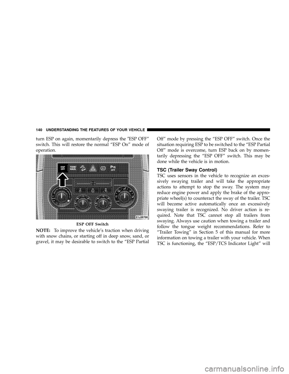
turn ESP on again, momentarily depress the9ESP OFFº
switch. This will restore the normal ªESP Onº mode of
operation.
NOTE:To improve the vehicle's traction when driving
with snow chains, or starting off in deep snow, sand, or
gravel, it may be desirable to switch to the ªESP PartialOffº mode by pressing the ªESP OFFº switch. Once the
situation requiring ESP to be switched to the ªESP Partial
Offº mode is overcome, turn ESP back on by momen-
tarily depressing the ªESP OFFº switch. This may be
done while the vehicle is in motion.
TSC (Trailer Sway Control)
TSC uses sensors in the vehicle to recognize an exces-
sively swaying trailer and will take the appropriate
actions to attempt to stop the sway. The system may
reduce engine power and apply the brake of the appro-
priate wheel(s) to counteract the sway of the trailer. TSC
will become active automatically once an excessively
swaying trailer is recognized. No driver action is re-
quired. Note that TSC cannot stop all trailers from
swaying. Always use caution when towing a trailer and
follow the tongue weight recommendations. Refer to
ªTrailer Towingº in Section 5 of this manual for more
information on towing a trailer with your vehicle. When
TSC is functioning, the ªESP/TCS Indicator Lightº will
ESP OFF Switch
140 UNDERSTANDING THE FEATURES OF YOUR VEHICLE
Page 143 of 405
²The ESP Control System will make buzzing or clicking
sounds when it is active. This is normal; the sounds
will stop when ESP becomes inactive following the
maneuver that caused the ESP activation.
REAR PARK ASSIST SYSTEMÐ IF EQUIPPED
The Rear Park Assist System provides visual and audible
indications of the distance between the rear fascia and the
detected obstacle when backing up. Refer to the Warning
Section and Note Section for limitations of this system
and recommendations.
The Rear Park Assist System will remember the last
system state (enabled or disabled) from the last ignition
cycle when the ignition is changed to the ON position.The Rear Park Assist System can be active only when the
shifter is in R (Reverse). If the Rear Park Assist System is
enabled at this shifter position, the system will be active
until the vehicle speed is increased to approximately 11
mph (18 km/h) or above. The system will be active again
if the vehicle speed is decreased to speeds less than
approximately 10 mph (16 km/h).
Rear Park Assist Sensors
The four Rear Park Assist Sensors, located in the rear
fascia, monitor the area behind the vehicle that is within
the sensors' field of view. The monitored area seems oval
in shape.
The sensors can detect obstacles from approximately 11.8
inches (30 cm) up to 59 inches (150 cm) from the rear
fascia in the horizontal direction, depending on the
location and orientation of the obstacle and the type of
obstacle.
142 UNDERSTANDING THE FEATURES OF YOUR VEHICLE
Page 147 of 405
Cleaning the Rear Park Assist System
Clean the Rear Park Assist Sensors with water, car wash
soap and a soft cloth. Do not use rough or hard cloths. Do
not scratch or poke the sensors. Otherwise, you could
damage the sensors.
REAR CAMERA Ð IF EQUIPPED
Vehicles with a Navigation radio may be equipped with
a rear view camera (located on the rear liftgate) that
allows you to see an on-screen image (on the navigation
radio screen) of the rear of your vehicle whenever the
vehicle is put into R (Reverse).
WARNING!
Drivers must be careful when backing up even when
using the rear camera system. Always check carefully
behind your vehicle, and be sure to check for pedes-
trians, animals, other vehicles, obstructions, or blind
spots before backing up. Failure to do so can result in
serious injury or death.
If snow, ice, mud, or anything else builds up on the
camera lens. Clean the lens, rinse with water, and dry
with a soft cloth.
Turning the Rear Camera On
1. To access the rear camera mode, select ªRear Cameraº
at the Systems Settings screen and press ENTER. Refer to
your ªNavigation User's Manualº for detailed operating
instructions.
146 UNDERSTANDING THE FEATURES OF YOUR VEHICLE
Page 179 of 405
of reasons, including the installation of replacement or
alternate tires or wheels on the vehicle that prevent the
TPMS from functioning properly. Always check the
TPMS malfunction telltale after replacing one or more
tires or wheels on your vehicle to ensure that the replace-
ment or alternate tires and wheels allow the TPMS to
continue to function properly.CAUTION!
The TPMS has been optimized for the original
equipment tires and wheels. TPMS pressures and
warning have been established for the tire size
equipped on your vehicle. Undesirable system opera-
tion or sensor damage may result when using re-
placement equipment that is not of the same size,
type, and/or style. After-market wheels can cause
sensor damage. Do not use aftermarket tire sealants
or balance beads if your vehicle is equipped with a
TPMS, as damage to the sensors may result.
13. Temperature Gauge
The temperature gauge shows engine coolant tempera-
ture. Any reading within the normal range indicates that
the engine cooling system is operating satisfactorily.
178 UNDERSTANDING YOUR INSTRUMENT PANEL
Page 190 of 405
Compass Variance
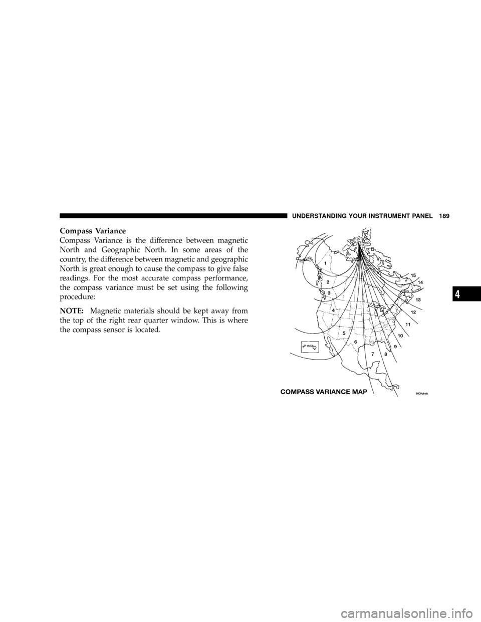
Compass Variance is the difference between magnetic
North and Geographic North. In some areas of the
country, the difference between magnetic and geographic
North is great enough to cause the compass to give false
readings. For the most accurate compass performance,
the compass variance must be set using the following
procedure:
NOTE:Magnetic materials should be kept away from
the top of the right rear quarter window. This is where
the compass sensor is located.
UNDERSTANDING YOUR INSTRUMENT PANEL 189
4