ESP JEEP GRAND CHEROKEE 2010 Owner handbook (in English)
[x] Cancel search | Manufacturer: JEEP, Model Year: 2010, Model line: GRAND CHEROKEE, Model: JEEP GRAND CHEROKEE 2010Pages: 350, PDF Size: 4.58 MB
Page 147 of 350
Venting Sunroof – ExpressPress the center “Vent” button on the sunroof
switch for less than one second and release,
and the sunroof glass will automatically vent
fully open from any position, then stop. This is
called “Express Vent”. During Express Vent
operation, any sunroof switch press or shade
switch press will stop the sunroof. If the shade
is closed when the vent switch is pressed, the
shade will automatically move to the middle
position before the sunroof begins Express
Vent operation.
Closing Sunroof – ExpressPress the sunroof switch forward for less than
one second and release, and the sunroof glass
will automatically close from any position, then
stop. This is called “Express Close”. During
Express Close operation, any sunroof switch
press or shade switch press will stop the sun-
roof.
Opening Power Shade – ExpressPress the shade switch rearward for less than
one second and release, and the shade will
automatically open, then stop. This is called
“Express Shade Open”. If the shade is forwardof the middle position, it will move to the middle
position then stop. If the shade is at or rearward
of the middle position, it will move to the full
open position then stop. During Express Shade
Open operation, any sunroof switch press or
shade switch press will stop the shade.
Closing Power Shade – ExpressPress the shade switch forward for less than
one second and release, and the shade will
automatically close, then stop. This is called
“Express Shade Close”. If the sunroof is not at
the closed position and the shade is rearward
of the middle position, the shade will move to
the middle position then stop. If the sunroof is
not at the closed position and the shade is at
the middle position, the sunroof will automati-
cally move to the fully closed position before
the shade begins Express Shade Close opera-
tion. During Express Shade Close operation,
any sunroof switch press or shade switch press
will stop the shade.
Sunroof and Power Shade
Movement – Manual
If any sunroof or shade switch is pressed and
held for more than one second, the sunroof orshade movement will continue only as long as
the switch is continuously held. Whenever the
switch is released, any sunroof or shade move-
ment will stop. This allows the sunroof or shade
to be stopped at any desired partially open
position.
Pinch Protect FeatureThis feature will detect an obstruction in the
opening of the sunroof or the shade during any
close operation. If an obstruction is detected,
the sunroof or shade will automatically reverse
direction to release the obstruction. If this oc-
curs, remove the obstruction and then press
the sunroof or shade switch forward to com-
plete the desired close motion.
Pinch Protect Override
Method 1:
If a known obstruction (ice, debris,
etc) prevents closing of the sunroof or shade,
press the corresponding switch forward and
hold for two seconds after the reversal motion
ends. After two seconds, all closing motions will
be manual and will have Pinch Protect dis-
abled. This will allow the sunroof or shade to
move towards the closed position.
143
Page 156 of 350
NOTE:
•To help control wind noise when the
crossbars are not in use, place the front
and rear crossbars approximately 24 in
(61 cm) apart. Optimal noise reduction
can then be achieved by adjusting the
front crossbar forward or aft using incre-
ments of 1 in (2.5 cm).
• If the rear crossbar (or any metallic ob-
ject) is placed over the satellite radio
antenna (if equipped), you may experi-
ence interruption of satellite radio recep-
tion. For improved satellite radio recep-
tion, avoid placing the rear crossbar over
the satellite radio antenna.
• The grab handles on the back of the
vehicle (if equipped) are not to be used as
a towing feature.CAUTION!
• To prevent damage to the roof of your
vehicle, do not carry any loads on the roof
rack without the crossbars installed. The
load should be secured and placed on top
of the crossbars, not directly on the roof. If
it is necessary to place the load on the roof,
place a blanket or some other protection
between the load and the roof surface.
• To avoid damage to the roof rack and
vehicle, do not exceed the maximum roof
rack load capacity of 150 lbs (68 kg).
Always distribute heavy loads as evenly as
possible and secure the load appropriately.
• Long loads which extend over the wind-
shield, such as wood panels or surfboards,
or loads with large frontal area should be
secured to both the front and rear of the
vehicle.
(Continued)CAUTION!(Continued)
• Travel at reduced speeds and turn corners
carefully when carrying large or heavy
loads on the roof rack. Wind forces, due to
natural causes or nearby truck traffic, can
add sudden upward lift to a load. This is
especially true on large flat loads and may
result in damage to the cargo or your
vehicle.
WARNING!
Cargo must be securely tied before driving
your vehicle. Improperly secured loads can fly
off the vehicle, particularly at high speeds,
resulting in personal injury or property dam-
age. Follow the roof rack cautions when car-
rying cargo on your roof rack.
152
Page 164 of 350
11. Tire Pressure Monitoring Telltale LightEach tire, including the spare (if
provided), should be checked
monthly, when cold and inflated to
the inflation pressure recom-
mended by the vehicle manufac-
turer on the vehicle placard or tire
inflation pressure label. (If your vehicle has tires
of a different size than the size indicated on the
vehicle placard or tire inflation pressure label,
you should determine the proper tire inflation
pressure for those tires.)
As an added safety feature, your vehicle has
been equipped with a Tire Pressure Monitoring
System (TPMS) that illuminates a low tire pres-
sure telltale when one or more of your tires is
significantly under-inflated. Accordingly, when
the low tire pressure telltale illuminates, you
should stop and check your tires as soon as
possible, and inflate them to the proper pres-
sure. Driving on a significantly under-inflated
tire causes the tire to overheat and can lead to
tire failure. Under-inflation also reduces fuel
efficiency and tire tread life, and may affect the
vehicle’s handling and stopping ability. Please note that the TPMS is not a substitute for
proper tire maintenance, and it is the driver’s
responsibility to maintain correct tire pressure,
even if under-inflation has not reached the level
to trigger illumination of the TPMS low tire
pressure telltale.
Your vehicle has also been equipped with a
TPMS malfunction indicator to indicate when
the system is not operating properly. The TPMS
malfunction indicator is combined with the low
tire pressure telltale. When the system detects
a malfunction, the telltale will flash for approxi-
mately one minute and then remain continu-
ously illuminated. This sequence will continue
upon subsequent vehicle start-ups as long as
the malfunction exists. When the malfunction
indicator is illuminated, the system may not be
able to detect or signal low tire pressure as
intended. TPMS malfunctions may occur for a
variety of reasons, including the installation of
replacement or alternate tires or wheels on the
vehicle that prevent the TPMS from functioning
properly. Always check the TPMS malfunction
telltale after replacing one or more tires or
wheels on your vehicle, to ensure that thereplacement or alternate tires and wheels allow
the TPMS to continue to function properly.
CAUTION!
The TPMS has been optimized for the original
equipment tires and wheels. TPMS pressures
and warning have been established for the tire
size equipped on your vehicle. Undesirable
system operation or sensor damage may re-
sult when using replacement equipment that
is not of the same size, type, and/or style.
Aftermarket wheels can cause sensor dam-
age. Do not use tire sealant from a can, or
balance beads if your vehicle is equipped with
a TPMS, as damage to the sensors may
result.
12. Position Light Indicator — If Equipped This indicator will illuminate when
the park lights or headlights are
turned on.
160
Page 165 of 350
13. Seat Belt Reminder LightWhen the ignition switch is first turned
to ON/RUN, this light will turn on for
four to eight seconds as a bulb check.
During the bulb check, if the driver or
front passenger’s seat belt is unbuckled, a
chime will sound. After the bulb check or when
driving, if the driver or front passenger seat belt
remains unbuckled, the Seat Belt Indicator
Light will flash or remain on continuously. Refer
to “Occupant Restraints” in “Things To Know
Before Starting Your Vehicle” for further infor-
mation.
14. Brake Warning Light This light monitors various brake
functions, including brake fluid
level and parking brake applica-
tion. If the brake light turns on, it
may indicate that the parking
brake is applied, that the brake
fluid level is low, or that there is a problem with
the anti-lock brake system reservoir.
If the light remains on when the parking brake
has been disengaged, and the fluid level is at
the full mark on the master cylinder reservoir, it
indicates a possible brake hydraulic system malfunction or that a problem with the Brake
Booster has been detected by the Anti-Lock
Brake System (ABS) / Electronic Stability Pro-
gram (ESP) system. In this case, the light will
remain on until the condition has been cor-
rected. If the problem is related to the brake
booster, the ABS pump will run when applying
the brake and a brake pedal pulsation may be
felt during each stop.
The dual brake system provides a reserve
braking capacity in the event of a failure to a
portion of the hydraulic system. A leak in either
half of the dual brake system is indicated by the
Brake Warning Light, which will turn on when
the brake fluid level in the master cylinder has
dropped below a specified level.
The light will remain on until the cause is
corrected.
NOTE:
The light may flash momentarily during
sharp cornering maneuvers, which change
fluid level conditions. The vehicle should
have service performed, and the brake fluid
level checked.
If brake failure is indicated, immediate repair is
necessary.
WARNING!
Driving a vehicle with the red brake light on is
dangerous. Part of the brake system may
have failed. It will take longer to stop the
vehicle. You could have a collision. Have the
vehicle checked immediately.
Vehicles equipped with the Anti-Lock Brake
System (ABS), are also equipped with Elec-
tronic Brake Force Distribution (EBD). In the
event of an EBD failure, the Brake Warning
Light will turn on along with the ABS Light.
Immediate repair to the ABS system is re-
quired.
Operation of the Brake Warning Light can be
checked by turning the ignition switch from the
OFF position to the ON/RUN position. The light
should illuminate for approximately two sec-
onds. The light should then turn off unless the
parking brake is applied or a brake fault is
detected. If the light does not illuminate, have
the light inspected by an authorized dealer.
161
Page 172 of 350
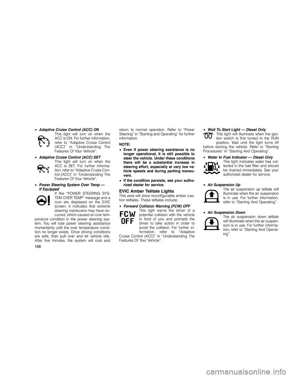
•Adaptive Cruise Control (ACC) ON
This light will turn on when the
ACC is ON. For further information,
refer to “Adaptive Cruise Control
(ACC)” in “Understanding The
Features Of Your Vehicle”.
• Adaptive Cruise Control (ACC) SET
This light will turn on when the
ACC is SET. For further informa-
tion, refer to “Adaptive Cruise Con-
trol (ACC)” in “Understanding The
Features Of Your Vehicle”.
• Power Steering System Over Temp —
If Equipped If the “POWER STEERING SYS-
TEM OVER TEMP” message and a
icon are displayed on the EVIC
screen, it indicates that extreme
steering maneuvers may have oc-
curred, which caused an over tem-
perature condition in the power steering sys-
tem. You will lose power steering assistance
momentarily until the over temperature condi-
tion no longer exists. Once driving conditions
are safe, then pull over and let vehicle idle.
After five minutes, the system will cool and return to normal operation. Refer to “Power
Steering” in “Starting and Operating” for further
information.
NOTE:
•
Even if power steering assistance is no
longer operational, it is still possible to
steer the vehicle. Under these conditions
there will be a substantial increase in
steering effort, especially at very low ve-
hicle speeds and during parking maneu-
vers.
• If the condition persists, see your autho-
rized dealer for service.
EVIC Amber Telltale LightsThis area will show reconfigurable amber cau-
tion telltales. These telltales include:
• Forward Collision Warning (FCW) OFF
This light warns the driver of a
potential collision with the vehicle
in front of you and prompts the
driver to take action in order to
avoid the collision. For further in-
formation, refer to “Adaptive
Cruise Control (ACC)” in “Understanding The
Features Of Your Vehicle”. •
Wait To Start Light — Diesel Only
This light will illuminate when the igni-
tion switch is first turned to the RUN
position. Wait until the light turns off
before starting the vehicle. Refer to “Starting
Procedures” in “Starting And Operating”.
• Water In Fuel Indicator — Diesel Only
This light indicates water has col-
lected in the fuel filter and should
be drained immediately. See your
authorized dealer for service.
• Air Suspension Up
The air suspension up telltale will
illuminate when the air suspension
is in use. For further information,
refer to “Starting And Operating”.
• Air Suspension Down
The air suspension down telltale
will illuminate when the air suspen-
sion is in use. For further informa-
tion, refer to “Starting And Operat-
ing”.
168
Page 181 of 350
1. Turn the ignition switch ON.
2. Press the UP or DOWN button until the
Setup (Customer-Programmable Features)
menu is reached, then press the SELECT but-
ton.
3. Press the DOWN button until the “Compass
Variance” message is displayed in the EVIC,
then press the SELECT button. The last vari-
ance zone number displays in the EVIC.
4. Press and release the SELECT button until
the proper variance zone is selected, accord-
ing to the map.
5. Press and release the RETURN button to
exit.
Customer-Programmable Features
(System Setup)
Personal Settings allows you to set and recall
features when the transmission is in PARK. If
the transmission is out of PARK or the vehicle
begins moving, a warning messageSETUP
NOT AVAILABLE, is followed in three seconds
by, VEHICLE NOT IN PARK.
Press and release the UP or DOWN button until
Setup displays in the EVIC. Use the UP or DOWN button to display one of
the following choices.
Select Language
When in this display you may select one of five
languages for all display nomenclature, includ-
ing the trip functions and the navigation system
(if equipped). Press the UP or DOWN button
while in this display and scroll through the
language choices. Press the SELECT button to
select English, Spanish (Español), French
(Français), Italian (Italiano), German (Deutsch),
and Dutch (Nederlands). Then, as you con-
tinue, the information will display in the se-
lected language.
Nav–Turn By Turn
When this feature is selected, the navigation
system utilizes voice commands, guiding
through the drive route, mile by mile, turn-by-
turn until the final destination is reached. To
make your selection, press and release the
SELECT button until a check-mark appears
next to the feature showing the system has
been activated or the check-mark is removed,
showing the system has been deactivated.
Auto Unlock Doors
When this feature is selected, all doors will
unlock when the vehicle is stopped and the
transmission is in the PARK or NEUTRAL posi-
tion and the driver’s door is opened. To make
your selection, press and release the SELECT
button until a check-mark appears next to the
feature showing the system has been acti-
vated, or the check-mark is removed showing
the system has been deactivated.
Remote Unlock Sequence
When
Unlock Driver Door Only On 1st Press
is selected, only the driver’s door will unlock on
the first press of the RKE transmitter UNLOCK
button. When Driver Door 1st Press is selected,
you must press the RKE transmitter UNLOCK
button twice to unlock the passenger’s doors.
When Unlock All Doors On 1st Press is
selected, all of the doors will unlock on the first
press of the RKE transmitter UNLOCK button.
To make your selection, scroll up or down until
the preferred setting is highlighted, then press
and release the SELECT button until a check-
mark appears next to the setting, showing that
setting has been selected.
177
Page 208 of 350
starter will disengage automatically in 20 sec-
onds. The starter can be disengaged by turn-
ing the ignition switch to the OFF position, if
required.
5. After the engine starts, allow it to idle for
approximately 30 seconds before driving. This
allows oil to circulate and lubricate the turbo-
charger.
Avoid prolonged idling in ambient tempera-
tures below 0°F (-18°C). Long periods of idling
may be harmful to your engine because com-
bustion chamber temperatures can drop so low
that the fuel may not burn completely. Incom-
plete combustion allows carbon and varnish to
form on piston rings and injector nozzles. Also,
the unburned fuel can enter the crankcase,
diluting the oil and causing rapid wear to the
engine.
Engine Warm Up
Avoid full throttle operation when the engine is
cold. When starting a cold engine, bring the
engine up to operating speed slowly to allow
the oil pressure to stabilize as the engine
warms up.NOTE:
High-speed, no-load running of a cold en-
gine can result in excessive white smoke
and poor engine performance. No-load en-
gine speeds should be kept under 1,200
RPM during the warm-up period, especially
in cold ambient temperature conditions.
If temperatures are below 32°F (0°C), operate
the engine at moderate speeds for five minutes
before full loads are applied.
Engine Idling – In Cold Weather
Avoid prolonged idling in ambient tempera-
tures below 0°F (-18°C). Long periods of idling
may be harmful to your engine because com-
bustion chamber temperatures can drop so low
that the fuel may not burn completely. Incom-
plete combustion allows carbon and varnish to
form on piston rings and injector nozzles. Also,
the unburned fuel can enter the crankcase,
diluting the oil and causing rapid wear to the
engine.
Stopping The Engine
Before turning off your turbo diesel engine,
always allow the engine to return to normal idle
speed and run for several seconds. This as-sures proper lubrication of the turbocharger.
This is particularly necessary after any period
of hard driving.
Idle the engine a few minutes before routine
shutdown. After full load operation, idle the
engine three to five minutes before shutting it
down. This idle period will allow the lubricating
oil and coolant to carry excess heat away from
the combustion chamber, bearings, internal
components, and turbocharger. This is espe-
cially important for turbocharged, charge air
cooled engines.
AUTOMATIC TRANSMISSION
CAUTION!
Damage to the transmission may occur if the
following precautions are not observed:
•
Shift into PARK only after the vehicle has
come to a complete stop.
• Shift into or out of REVERSE only after the
vehicle has come to a complete stop and
the engine is at idle speed.
(Continued)
204
Page 210 of 350
Five-Speed Automatic TransmissionThe electronically-controlled transmission pro-
vides a precise shift schedule. The transmis-
sion electronics are self-calibrating; therefore,
the first few shifts on a new vehicle may be
somewhat abrupt. This is a normal condition,
and precision shifts will develop within a few
hundred miles/kilometers.
Gear Ranges
NOTE:
After selecting any gear range, wait a mo-
ment to allow the selected gear to engage
before accelerating. This is especially im-
portant when the engine is cold. If there is a
need to restart the engine, be sure to turn
the ignition switch to the LOCK position
before restarting. Transmission gear en-
gagement may be delayed after restarting
the engine if the ignition switch is not turned
to the LOCK position first.
PARK
This range supplements the parking brake by
locking the transmission. The engine can be
started in this range. Never use PARK while the
vehicle is in motion. Apply the parking brakewhen leaving the vehicle in this range. Always
apply the parking brake first, then place the
shift lever into the PARK position.
WARNING!
•
Never use the PARK position as a substi-
tute for the parking brake. Always apply the
parking brake fully when parked to guard
against vehicle movement and possible
injury or damage.
• It is dangerous to move the shift lever out of
PARK or NEUTRAL if the engine speed is
higher than idle speed. If your foot is not
firmly on the brake pedal, the vehicle could
accelerate quickly forward or in reverse.
You could lose control of the vehicle and hit
someone or something. Only shift into gear
when the engine is idling normally and
when your right foot is firmly on the brake
pedal.
REVERSE
This range is for moving the vehicle backward.
Use only after the vehicle has come to a
complete stop. NEUTRAL
This range is used when vehicle is standing for
prolonged periods with engine running. Engine
may be started in this range. Set the parking
brake if you must leave the vehicle.
NOTE:
Towing the vehicle, coasting, or driving for
any other reason with the shift lever in
NEUTRAL can result in severe transmission
damage. Refer to “Recreational Towing” in
“Starting and Operating” and “Towing a Dis-
abled Vehicle” in “What To Do In Emergen-
cies” for further information.
DRIVE
This range should be selected only when the
vehicle is at a complete stop and the brakes
are firmly applied. The transmission automati-
cally upshifts through fifth gear. The DRIVE
position provides optimum driving characteris-
tics under all normal operating conditions.
Electronic Range Select (ERS) Operation
The Electronic Range Select (ERS) shift control
allows you to move the shift lever left (-) or right
(+) when the shift lever is in the DRIVE position,
allowing you to limit the highest available gear.
206
Page 213 of 350
The “TOW/HAUL Indicator Light” will illuminate
in the instrument cluster to indicate when the
switch has been activated. Pressing the switch
a second time restores normal operation. If the
TOW/HAUL mode is desired, the switch must
be pressed each time the engine is started.
In high ambient temperatures with sustained
high engine speed and load, an upshift, fol-
lowed shortly thereafter by a downshift, may
occur. The “TOW/HAUL Indicator Light” will
turn off. This is a normal part of the overheat
protection strategy when operating in the TOW/
HAUL mode.
Transmission Limp Home Mode
Transmission function is monitored for abnor-
mal conditions. If a condition is detected that
could result in transmission damage, the Trans-
mission Limp Home Mode will be engaged. In
this mode, the transmission will remain in the
current gear (3.6L and 3.0L Diesel engine) or in
direct gear (5.7L engine) until the vehicle is
brought to a stop.To reset the transmission, use the following
procedure:
1. Stop the vehicle.
2. Move the shift lever into the PARK position.
3. Turn the engine off, and be sure to turn the
ignition switch to the LOCK position.
4. Wait approximately 10 seconds, then restart
the engine.
5. Move the shift lever to the desired gear
range.
If the problem is no longer detected, the trans-
mission will return to normal operation. If the
problem persists, PARK, REVERSE, and NEU-
TRAL will continue to operate. Only second
gear (3.6L and 3.0L Diesel engine) or third gear
(5.7L engine) will be available in the DRIVE
position. Have the transmission checked at
your authorized dealer as soon as possible.
Torque Converter Clutch
A feature, designed to improve fuel economy,
has been included in the automatic transmis-
sion on your vehicle. A clutch within the torque
converter engages automatically, at a cali-brated speed, at light throttle. It engages at
higher speeds under heavier acceleration. This
may result in a slightly different feeling or
response during normal operation in high gear.
When the vehicle speed drops below a cali-
brated speed, or during acceleration, the
clutch automatically and smoothly disengages.
NOTE:
•
The torque converter clutch will not en-
gage until the transmission fluid and en-
gine coolant are warm [usually after 1 to
3 miles (1.6 to 4.8 km) of driving]. Because
the engine speed is higher when the
torque converter clutch is not engaged, it
may seem as if the transmission is not
shifting into Overdrive when cold. This is
normal. Manually shifting (using the ERS
shift control) between 4 (direct gear) and
5/D (Overdrive gear) positions will dem-
onstrate that the transmission is able to
shift into and out of Overdrive. For ve-
hicles with 5.7L engines (which have two
Overdrive gears), the transmission may
not shift into the top Overdrive gear (nor-
mal fifth gear) until the transmission fluid
and engine coolant are warm.
209
Page 224 of 350
When descending mountains or hills, repeated
braking can cause brake fade with loss of
braking control. Avoid repeated heavy braking
by downshifting the transmission whenever
possible.
After Driving Off-RoadOff-road operation puts more stress on your
vehicle than does most on-road driving. After
going off-road, it is always a good idea to
check for damage. That way you can get any
problems taken care of right away and have
your vehicle ready when you need it.
•Completely inspect the underbody of your
vehicle. Check tires, body structure, steer-
ing, suspension, and exhaust system for
damage.
• Inspect the radiator for mud and debris and
clean as required.
• Check threaded fasteners for looseness,
particularly on the chassis, drivetrain com-
ponents, steering, and suspension. Re-
tighten them, if required, and torque to the
values specified in the Service Manual. •
Check for accumulations of plants or brush.
These things could be a fire hazard. They
might hide damage to fuel lines, brake hoses,
axle pinion seals, and propeller shafts.
• After extended operation in mud, sand, wa-
ter, or similar dirty conditions, have the ra-
diator, fan, brake rotors, wheels, brake lin-
ings, and axle yokes inspected and cleaned
as soon as possible.
WARNING!
Abrasive material in any part of the brakes
may cause excessive wear or unpredictable
braking. You might not have full braking power
when you need it to prevent a collision. If you
have been operating your vehicle in dirty
conditions, get your brakes checked and
cleaned as necessary.
• If you experience unusual vibration after
driving in mud, slush or similar conditions,
check the wheels for impacted material. Im-
pacted material can cause a wheel imbal-
ance and freeing the wheels of it will correct
the situation.
POWER STEERING
3.6L Engine and 3.0L Diesel Engine
Your vehicle is equipped with an electro-
hydraulic power steering system that will give
you good vehicle response and increased ease
of maneuverability in tight spaces. The system
will vary its assist to provide light efforts while
parking and good feel while driving. If the
electro-hydraulic power steering system expe-
riences a fault that prevents it from providing
power steering assist, then the system will
provide mechanical steering capability.
CAUTION!
Extreme steering maneuvers may cause the
electrically driven pump to reduce or stop
power steering assistance in order to prevent
damage to the system. Normal operation will
resume once the system is allowed to cool.
If the “SERVICE POWER STEER-
ING SYSTEM” message and a
flashing icon are displayed on the
EVIC screen, it indicates that the
vehicle needs to be taken to the
220