warning JEEP GRAND CHEROKEE 2010 WK / 3.G Owner's Manual
[x] Cancel search | Manufacturer: JEEP, Model Year: 2010, Model line: GRAND CHEROKEE, Model: JEEP GRAND CHEROKEE 2010 WK / 3.GPages: 84, PDF Size: 14.64 MB
Page 17 of 84
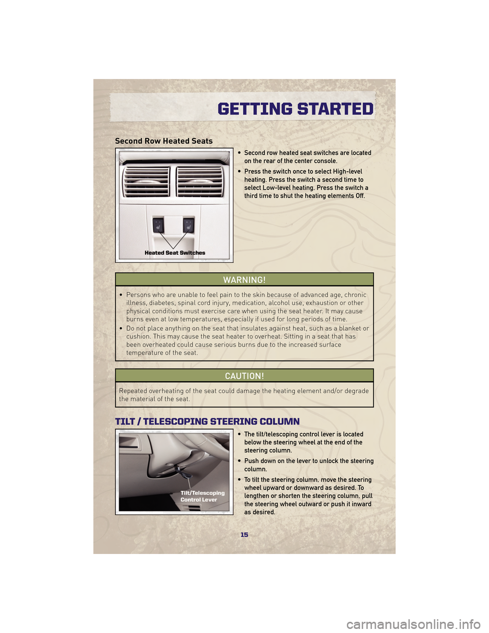
Second Row Heated Seats
• Second row heated seat switches are locatedon the rear of the center console.
• Press the switch once to select High-level heating. Press the switch a second time to
select Low-level heating. Press the switch a
third time to shut the heating elements Off.
WARNING!
• Persons who are unable to feel pain to the skin because of advanced age, chronic illness, diabetes, spinal cord injury, medication, alcohol use, exhaustion or other
physical conditions must exercise care when using the seat heater. It may cause
burns even at low temperatures, especially if used for long periods of time.
• Do not place anything on the seat that insulates against heat, such as a blanket or cushion. This may cause the seat heater to overheat. Sitting in a seat that has
been overheated could cause serious burns due to the increased surface
temperature of the seat.
CAUTION!
Repeated overheating of the seat could damage the heating element and/or degrade
the material of the seat.
TILT / TELESCOPING STEERING COLUMN
• The tilt/telescoping control lever is locatedbelow the steering wheel at the end of the
steering column.
• Push down on the lever to unlock the steering column.
• To tilt the steering column, move the steering wheel upward or downward as desired. To
lengthen or shorten the steering column, pull
the steering wheel outward or push it inward
as desired.
15
GETTING STARTED
Page 18 of 84
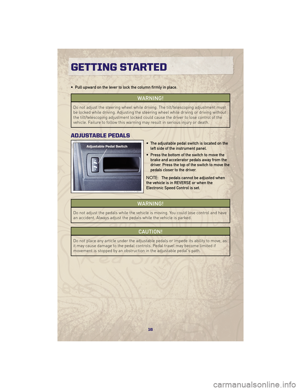
• Pull upward on the lever to lock the column firmly in place.
WARNING!
Do not adjust the steering wheel while driving. The tilt/telescoping adjustment must
be locked while driving. Adjusting the steering wheel while driving or driving without
the tilt/telescoping adjustment locked could cause the driver to lose control of the
vehicle. Failure to follow this warning may result in serious injury or death.
ADJUSTABLE PEDALS
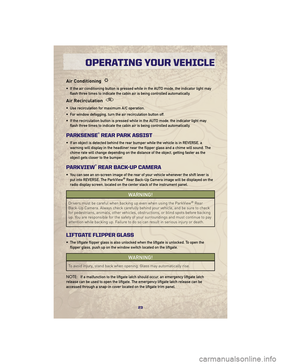
• The adjustable pedal switch is located on theleft side of the instrument panel.
• Press the bottom of the switch to move the brake and accelerator pedals away from the
driver. Press the top of the switch to move the
pedals closer to the driver.
NOTE: The pedals cannot be adjusted when
the vehicle is in REVERSE or when the
Electronic Speed Control is set.
WARNING!
Do not adjust the pedals while the vehicle is moving. You could lose control and have
an accident. Always adjust the pedals while the vehicle is parked.
CAUTION!
Do not place any article under the adjustable pedals or impede its ability to move, as
it may cause damage to the pedal controls. Pedal travel may become limited if
movement is stopped by an obstruction in the adjustable pedal’s path.
GETTING STARTED
16
Page 22 of 84
Rear Wiper
Wiper Operation
• Rotate the center portion of the lever forward to the first detent for rear wiper operation.
Washer Operation
• Rotate the center portion of the lever past the first detent to activate the rear washer.
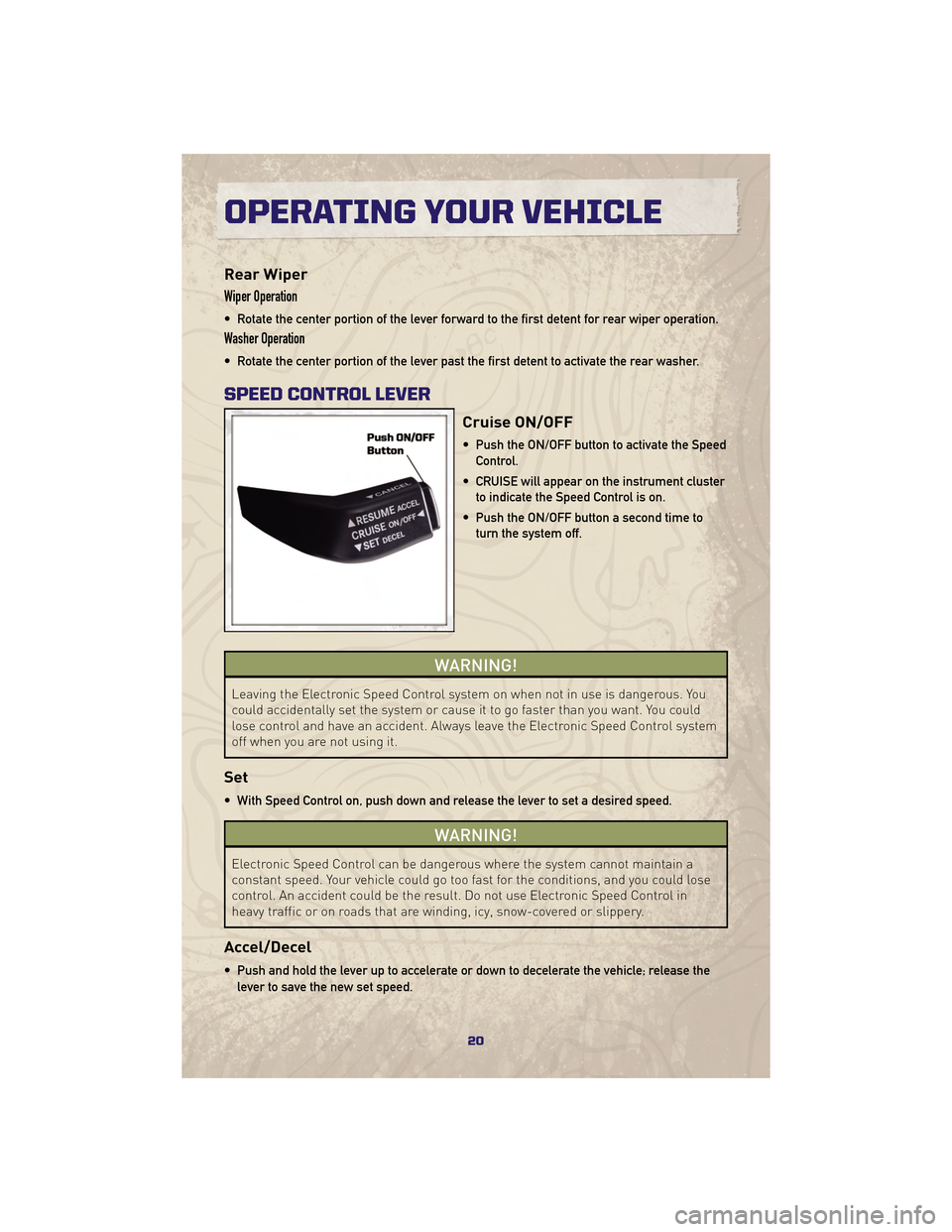
SPEED CONTROL LEVER
Cruise ON/OFF
• Push the ON/OFF button to activate the SpeedControl.
• CRUISE will appear on the instrument cluster to indicate the Speed Control is on.
• Push the ON/OFF button a second time to turn the system off.
WARNING!
Leaving the Electronic Speed Control system on when not in use is dangerous. You
could accidentally set the system or cause it to go faster than you want. You could
lose control and have an accident. Always leave the Electronic Speed Control system
off when you are not using it.
Set
• With Speed Control on, push down and release the lever to set a desired speed.
WARNING!
Electronic Speed Control can be dangerous where the system cannot maintain a
constant speed. Your vehicle could go too fast for the conditions, and you could lose
control. An accident could be the result. Do not use Electronic Speed Control in
heavy traffic or on roads that are winding, icy, snow-covered or slippery.
Accel/Decel
• Push and hold the lever up to accelerate or down to decelerate the vehicle; release the
lever to save the new set speed.
OPERATING YOUR VEHICLE
20
Page 25 of 84
Air Conditioning
• If the air conditioning button is pressed while in the AUTO mode, the indicator light mayflash three times to indicate the cabin air is being controlled automatically.
Air Recirculation
• Use recirculation for maximum A/C operation.
• For window defogging, turn the air recirculation button off.
• If the recirculation button is pressed while in the AUTO mode, the indicator light mayflash three times to indicate the cabin air is being controlled automatically.
PARKSENSE®REAR PARK ASSIST
• If an object is detected behind the rear bumper while the vehicle is in REVERSE, awarning will display in the headliner near the flipper glass and a chime will sound. The
chime rate will change depending on the distance of the object, getting faster as the
object gets closer to the bumper.
PARKVIEW®REAR BACK-UP CAMERA
• You can see an on-screen image of the rear of your vehicle whenever the shift lever isput into REVERSE. The ParkView®Rear Back-Up Camera image will be displayed on the
radio display screen, located on the center stack of the instrument panel.
WARNING!
Drivers must be careful when backing up even when using the ParkView®Rear
Back-Up Camera. Always check carefully behind your vehicle, and be sure to check
for pedestrians, animals, other vehicles, obstructions, or blind spots before backing
up. You are responsible for the safety of your surroundings and must continue to pay
attention while backing up. Failure to do so can result in serious injury or death.
LIFTGATE FLIPPER GLASS
• The liftgate flipper glass is also unlocked when the liftgate is unlocked. To open the
flipper glass, push up on the window switch located on the liftgate.
WARNING!
To avoid injury, stand back when opening. Glass may automatically rise.
NOTE: If a malfunction to the liftgate latch should occur, an emergency liftgate latch
release can be used to open the liftgate. The emergency liftgate latch release can be
accessed through a snap-in cover located on the liftgate trim panel.
23
OPERATING YOUR VEHICLE
Page 26 of 84
WARNING!
Driving with the flipper glass open can allow poisonous exhaust gases into your
vehicle. You and your passengers could be injured by these fumes. Keep the flipper
glass closed when you are operating the vehicle.
POWER SUNROOF
• The power sunroof switch is located on the overhead console.
WARNING!
• Never leave children in a vehicle with the key in the ignition switch. Occupants,particularly unattended children, can become entrapped by the power sunroof
while operating the power sunroof switch. Such entrapment may result in serious
injury or death.
• In an accident, there is a greater risk of being thrown from a vehicle with an open sunroof. You could also be seriously injured or killed. Always fasten your seat belt
properly and make sure all passengers are properly secured too.
• Do not allow small children to operate the sunroof. Never allow your fingers, other body parts, or any object to project through the sunroof opening. Injury may result.
Opening Sunroof
Express
• Press the switch rearward and release. The sunroof will fully open and stop
automatically.
Closing Sunroof
Express
• Press the switch forward and release. The sunroof will close automatically from anyposition.
Manual Open/Close
• Press and hold the switch rearward to open or forward to close the sunroof. Any releaseof the switch will stop the movement, and the sunroof will remain in a partially open or
closed position until the switch is pressed again.
Venting Sunroof
• Press and release the "VENT" button, and the sunroof will open to the vent position. Thisis called “Express Vent” and will occur regardless of sunroof position. During Express
Vent operation, any movement of the switch will stop the sunroof.
OPERATING YOUR VEHICLE
24
Page 36 of 84
WARNING!
• Your motorized door or gate will open and close while you are training theuniversal transceiver. Do not train the transceiver if people or pets are in the path
of the door or gate. Only use this transceiver with a garage door opener that has a
“stop and reverse” feature as required by Federal safety standards. This includes
most garage door opener models manufactured after 1982. Do not use a garage
door opener without these safety features. Call toll-free 1–800–355–3515 or, on
the Internet, at www.HomeLink.com for safety information or assistance.
• Vehicle exhaust contains Carbon Monoxide (CO), a dangerous gas. Do not run your vehicle in the garage while training the transceiver. Exhaust gas can cause serious
injury or death.
NOTE: If you are having difficulty training your HomeLink
®and your garage door was
manufactured after 1995, you may have a rolling code system. Follow the steps below for
programming a rolling code system.
Programming A Rolling Code System
• At the garage door opener motor (in the garage), locate the “learn” or “training” button. This can usually be found where the hanging antenna wire is attached to the garage door
opener motor (it is NOT the button normally used to open and close the door).
• Firmly press and release the “learn” or “training” button. The name and color of the button may vary by manufacturer. Within 30 seconds, return to the vehicle and press the
programmed HomeLink
®button twice (holding the button for two seconds each time). If
the device is plugged in and activates, programming is complete.
• If the device does not activate, press the button a third time (for two seconds) to complete the training.
Using HomeLink®
• To operate, simply press and release the programmed HomeLink®button and the
trained device will operate.
• Refer to your Owner’s Manual on the DVD for further details. If you have any problems programming HomeLink
®, or require assistance, please call toll-free 1–800–355–3515,
or on the Internet, at www.HomeLink.com.
ELECTRONICS
34
Page 37 of 84
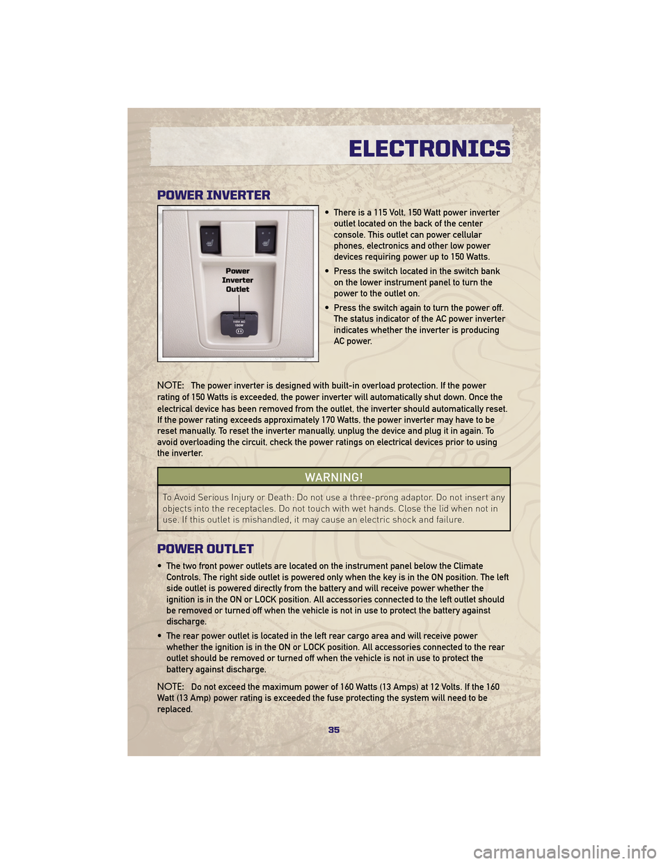
POWER INVERTER
• There is a 115 Volt, 150 Watt power inverteroutlet located on the back of the center
console. This outlet can power cellular
phones, electronics and other low power
devices requiring power up to 150 Watts.
• Press the switch located in the switch bank on the lower instrument panel to turn the
power to the outlet on.
• Press the switch again to turn the power off. The status indicator of the AC power inverter
indicates whether the inverter is producing
AC power.
NOTE: The power inverter is designed with built-in overload protection. If the power
rating of 150 Watts is exceeded, the power inverter will automatically shut down. Once the
electrical device has been removed from the outlet, the inverter should automatically reset.
If the power rating exceeds approximately 170 Watts, the power inverter may have to be
reset manually. To reset the inverter manually, unplug the device and plug it in again. To
avoid overloading the circuit, check the power ratings on electrical devices prior to using
the inverter.
WARNING!
To Avoid Serious Injury or Death: Do not use a three-prong adaptor. Do not insert any
objects into the receptacles. Do not touch with wet hands. Close the lid when not in
use. If this outlet is mishandled, it may cause an electric shock and failure.
POWER OUTLET
• The two front power outlets are located on the instrument panel below the Climate Controls. The right side outlet is powered only when the key is in the ON position. The left
side outlet is powered directly from the battery and will receive power whether the
ignition is in the ON or LOCK position. All accessories connected to the left outlet should
be removed or turned off when the vehicle is not in use to protect the battery against
discharge.
• The rear power outlet is located in the left rear cargo area and will receive power whether the ignition is in the ON or LOCK position. All accessories connected to the rear
outlet should be removed or turned off when the vehicle is not in use to protect the
battery against discharge.
NOTE: Do not exceed the maximum power of 160 Watts (13 Amps) at 12 Volts. If the 160
Watt (13 Amp) power rating is exceeded the fuse protecting the system will need to be
replaced.
35
ELECTRONICS
Page 38 of 84
Uconnect™ Phone
• The Uconnect™ Phone is a voice-activated, hands-free, in-vehicle communicationssystem.
• The Uconnect™ Phone allows you to dial a phone number with your cellular phone using simple voice commands.
• For vehicles equipped with Video Entertainment System (VES)™, refer to the Uconnect™ Phone section of the Uconnect™ User's Manual on the DVD for further details.
• For vehicles not equipped with VES™, refer to your vehicle Owner's Manual on the DVD for further details.
WARNING!
• Any voice commanded system should be used only in safe driving conditions following local laws and phone use. All attention should be kept on the roadway
ahead. Failure to do so may result in an accident causing serious injury or death.
• Your phone must be turned on and paired to the Uconnect™ Phone to allow use of this vehicle feature in emergency situations, when the cellular phone has network
coverage and stays paired to the Uconnect™ Phone.
NOTE: The Uconnect™ Phone requires a cellular phone equipped with the Bluetooth
®
Hands-Free Profile, Version 0.96 or higher. For Uconnect™ customer support, call
1–877–855–8400.
Phone Pairing
NOTE:Pairing is a one-time initial setup before using the phone. You will also need to
follow the Bluetooth®instructions in your cell phone user guide to complete the phone
pairing setup.
• Press the Phone button
to begin.
• Wait for the “ready” prompt and beep.
• (After the BEEP), say “Uconnect setup”.
• (After the BEEP), say “phone pairing”.
• (After the BEEP), say “pair a phone”.
• Follow the audible prompts.
• You will be asked to create a four-digit PIN which you will later need to enter into your phone (typically...settings, Bluetooth
®, device, list, new).
• You will then be prompted to give the phone pairing a name (each phone paired should have a unique name).
• Next you will be asked to give this new pairing a priority of 1 thru 7 (up to seven phones may be paired).
ELECTRONICS
36
Page 40 of 84
VOICE COMMAND
• The Voice Command system allows you to control your AM, FM radio, satellite radio, discplayer, and a memo recorder. When you press the Voice Command button
,you
will hear a beep. The beep is your signal to give a command. If you do not say a
command within a few seconds, the system will present you with a list of options. If you
ever wish to interrupt the system while it lists options, press the Voice Command
button
, listen for the BEEP, and say your command.
• For vehicles equipped with Video Entertainment System (VES)™, refer to the Voice Command section of the Uconnect™ User's Manual on the DVD for further details.
• For vehicles not equipped with VES™, refer to your vehicle Owner's Manual on the DVD for Voice Command information.
Changing The Volume
• Start a dialogue by pressing the Voice Command button, then say a command
(e.g., “tutorial”).
• Use the radio ON/OFF VOLUME rotary knob to adjust the volume to a comfortable level while the Voice Command system is speaking. Please note the volume setting for Voice
Command is different than the audio system.
WARNING!
Any voice commanded system should be used only in safe driving conditions and all
attention should be kept on the roadway ahead. Failure to do so may result in an
accident causing serious injury or death.
NOTE: To access the tutorial, press the Voice Command button
. After the BEEP,
say “tutorial”. Press any hard-key or touch the display to cancel the tutorial.
ELECTRONICS
38
Page 41 of 84
FOUR-WHEEL DRIVE
OPERATION
Quadra-Trac I®Operating
Instructions/Precautions
• The Quadra-Trac I®is a single-speed
(HI range only) transfer case, which
provides convenient full-time
four–wheel drive. No driver interaction
is required. The Brake Traction Control
(BTC) System, which combines
standard ABS and Traction Control,
provides resistance to any wheel that is
slipping to allow additional torque
transfer to wheels with traction.
Quadra-Trac II®/Quadra-Drive
II®Operating Instructions/
Precautions
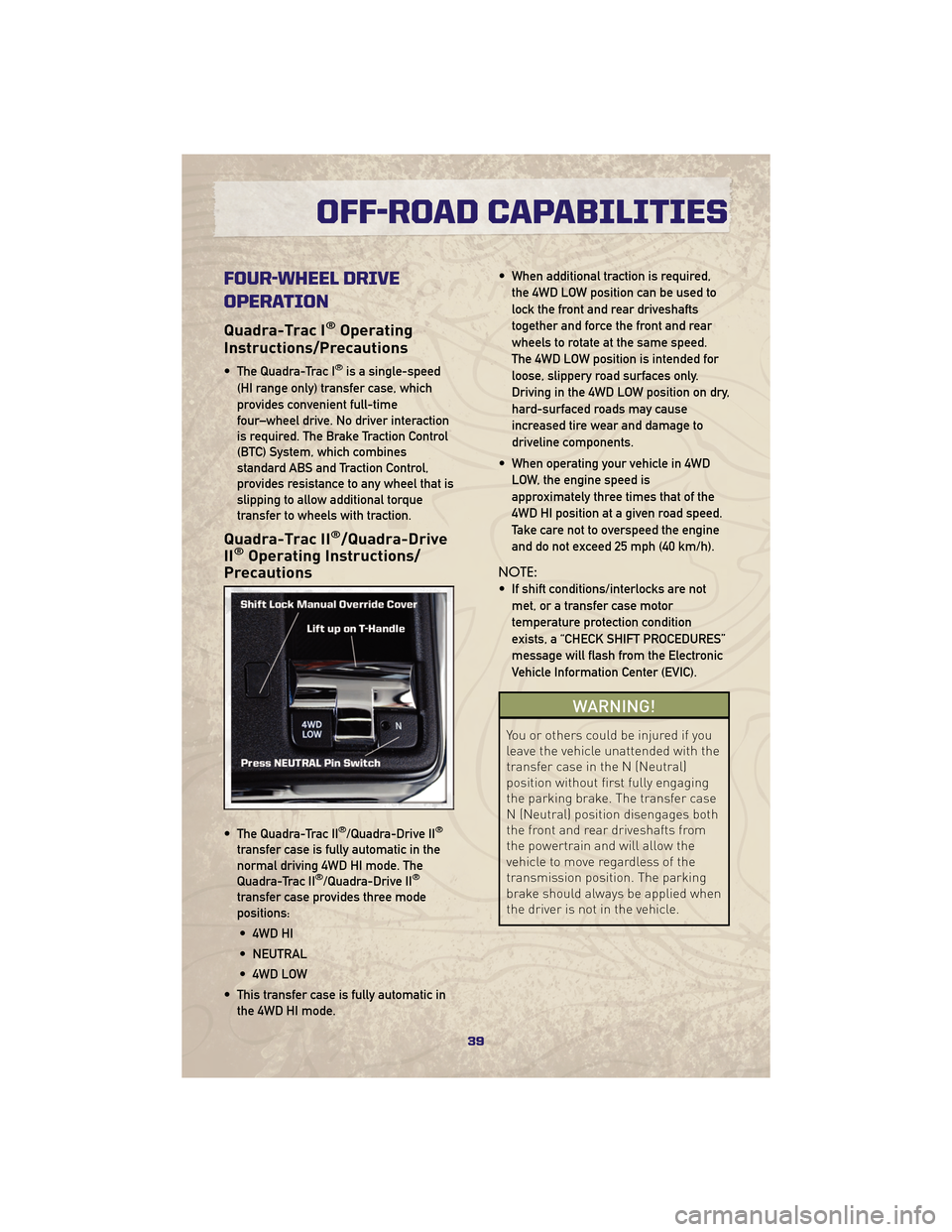
• The Quadra-Trac II®/Quadra-Drive II®
transfer case is fully automatic in the
normal driving 4WD HI mode. The
Quadra-Trac II
®/Quadra-Drive II®
transfer case provides three mode
positions:
• 4WD HI
• NEUTRAL
• 4WD LOW
• This transfer case is fully automatic in the 4WD HI mode. • When additional traction is required,
the 4WD LOW position can be used to
lock the front and rear driveshafts
together and force the front and rear
wheels to rotate at the same speed.
The 4WD LOW position is intended for
loose, slippery road surfaces only.
Driving in the 4WD LOW position on dry,
hard-surfaced roads may cause
increased tire wear and damage to
driveline components.
• When operating your vehicle in 4WD LOW, the engine speed is
approximately three times that of the
4WD HI position at a given road speed.
Take care not to overspeed the engine
and do not exceed 25 mph (40 km/h).
NOTE:
• If shift conditions/interlocks are not met, or a transfer case motor
temperature protection condition
exists, a “CHECK SHIFT PROCEDURES”
message will flash from the Electronic
Vehicle Information Center (EVIC).
WARNING!
You or others could be injured if you
leave the vehicle unattended with the
transfer case in the N (Neutral)
position without first fully engaging
the parking brake. The transfer case
N (Neutral) position disengages both
the front and rear driveshafts from
the powertrain and will allow the
vehicle to move regardless of the
transmission position. The parking
brake should always be applied when
the driver is not in the vehicle.
39
OFF-ROAD CAPABILITIES