Air C JEEP GRAND CHEROKEE 2012 WK2 / 4.G Owner's Manual
[x] Cancel search | Manufacturer: JEEP, Model Year: 2012, Model line: GRAND CHEROKEE, Model: JEEP GRAND CHEROKEE 2012 WK2 / 4.GPages: 148, PDF Size: 5.91 MB
Page 99 of 148
24-HOUR TOWING ASSISTANCE
• Dial toll-free 1-800-521-2779 or 1-800-363-4869 for Canadian residents.
• Provide your name, vehicle identification number and license platenumber.
• Provide your location, including telephone number, from which you are calling.
• Briefly describe the nature of the problem and answer a few simple questions.
• You will be given the name of the service provider and an estimated time of arrival. If you feel you are in an “unsafe situation”, please let us know.
With your consent, we will contact local police or safety authorities.
INSTRUMENT CLUSTER WARNING LIGHTS
- Tire Pressure Monitoring System (TPMS) Light
• Each tire, including the spare (if provided), should be checked monthly,when cold and inflated to the inflation pressure recommended by the
vehicle manufacturer on the vehicle placard or tire inflation pressure
label. (If your vehicle has tires of a different size than the size indicated
on the vehicle placard or tire inflation pressure label, you should
determine the proper tire inflation pressure for those tires.)
• As an added safety feature, your vehicle has been equipped with a Tire Pressure Monitoring System (TPMS) that illuminates a low tire pressure
telltale when one or more of your tires is significantly under-inflated.
Accordingly, when the low tire pressure telltale illuminates, you should
stop and check your tires as soon as possible, and inflate them to the
proper pressure. Driving on a significantly under-inflated tire causes the
tire to overheat and can lead to tire failure. Under-inflation also reduces
fuel efficiency and tire tread life, and may affect the vehicle’s handling
and stopping ability.
• IF THE LIGHT STARTS FLASHING INDICATING A LOW TIRE PRESSURE,
ADJUST THE AIR PRESSURE IN THE LOW TIRE TO THE AIR PRESSURE
SHOWN ON THE VEHICLE PLACARD OR TIRE INFLATION PRESSURE
LABEL LOCATED ON THE DRIVER'S DOOR. NOTE: AFTER INFLATION,
THE VEHICLE MAY NEED TO BE DRIVEN FOR 20 MINUTES BEFORE
THE FLASHING LIGHT WILL TURN OFF.
• Please note that the TPMS is not a substitute for proper tire maintenance, and it is the driver’s responsibility to maintain correct tire
pressure, even if under-inflation has not reached the level to trigger
illumination of the TPMS low tire pressure telltale.
WHAT TO DO IN EMERGENCIES
97
Page 100 of 148
• Your vehicle has also been equipped with a TPMS malfunction indicatorto indicate when the system is not operating properly. The TPMS
malfunction indicator is combined with the low tire pressure telltale.
When the system detects a malfunction, the telltale will flash for
approximately one minute and then remain continuously illuminated. This
sequence will continue each time the vehicle is restarted as long as the
malfunction exists.
• When the malfunction indicator is illuminated, the system may not be able to detect or signal low tire pressure as intended. TPMS malfunctions
may occur for a variety of reasons, including the installation of
replacement or alternate tires or wheels on the vehicle that prevent the
TPMS from functioning properly. Always check the TPMS malfunction
telltale after replacing one or more tires or wheels on your vehicle, to
ensure that the replacement or alternate tires and wheels allow the TPMS
to continue to function properly.
NOTE: Tire pressures change by approximately 1 psi (7 kPa) per 12° F (7° C)
of air temperature change. Keep this in mind when checking tire pressure
inside a garage, especially in the Winter. Example: If garage temperature is
68°F (20°C) and the outside temperature is 32°F (0°C), then the cold tire
inflation pressure should be increased by 3 psi (21 kPa), which equals 1 psi
(7 kPa) for every 12°F (7°C) for this outside temperature condition.
CAUTION!
The TPMS has been optimized for the original equipment tires and
wheels. TPMS pressures and warning have been established for the
tire size equipped on your vehicle. Undesirable system operation or
sensor damage may result when using replacement equipment that is
not of the same size, type, and/or style. Aftermarket wheels can cause
sensor damage. Do not use tire sealant from a can, or balance beads if
your vehicle is equipped with a TPMS, as damage to the sensors may
result.
BRAKE- Brake Warning Light
• The Brake Warning light illuminates when there is either a system malfunction or the parking brake is applied. If the light is on and the
parking brake is not applied, it indicates a possible brake hydraulic
malfunction, brake booster problem or an Anti-Lock Brake System
problem.
• Please have your vehicle serviced immediately.
WARNING!
Driving a vehicle with the red brake light on is dangerous. Part of the
brake system may have failed. It will take longer to stop the vehicle.
You could have a collision. Have the vehicle checked immediately.
WHAT TO DO IN EMERGENCIES
98
Page 102 of 148
- Electronic Throttle Control (ETC) Light
• This light informs you of a problem with the Electronic Throttle Control(ETC) system.
• If a problem is detected, the light will come on while the engine is running. Cycle the ignition key when the vehicle has completely stopped
and the shift lever is placed in the PARK position; the light should turn
off.
• If the light remains lit with the engine running, your vehicle will usually be drivable; however, see an authorized service center i mmediately. If the
light is flashing when the engine is running, immediate service is required
and you may experience reduced performance, an elevated/rough idle or
engine stall and your vehicle may require towing.
- Air Bag Warning Light
• If the light is not on during starting, stays on, or turns on while driving, have the vehicle serviced by an authorized service center immediately.
Fuel Cap/Loose Gas Cap Message
• If a “gas cap” message (shown as Check Gascap) appears, tighten thegas cap until a “clicking” sound is heard.
• If the message continues to appear for more than three days after tightening the gas cap, have the vehicle serviced by an authorized
service center immediately.
Oil Change IndicatorMessage
• If an “oil change” message (shown as Oil Change Required) appears and a single chime sounds, it is time for your next required oil change.
Resetting The Light After Servicing
Vehicles Equipped With Keyless Enter-N-Go™ • Without pressing the brake pedal, push the ENGINE START/STOP button and cycle the ignition to the ON/RUN position (Do not start the engine.)
• Fully depress the accelerator pedal, slowly, three times within 10 seconds.
• Without pressing the brake pedal, push the ENGINE START/STOP button once to return the ignition to the OFF/LOCK position.
Vehicles Not Equipped With Keyless Enter-N-Go™
• Turn the ignition switch to the ON/RUN position (Do not start the engine.)
• Fully depress the accelerator pedal, slowly, three times within 10 seconds.
• Turn the ignition switch to the OFF/LOCK position.
WHAT TO DO IN EMERGENCIES
100
Page 103 of 148
IF YOUR ENGINE OVERHEATS
• In any of the following situations, you can reduce the potential foroverheating by taking the appropriate action.
• On the highways — slow down.
• In city traffic — while stopped, place the transmission in NEUTRAL, but do not increase engine idle speed.
NOTE: There are steps that you can take to slow down an impending
overheat condition:
• If your air conditioner (A/C) is on, turn it off. The A/C system adds heat to the engine cooling system and turning the A/C off can help remove this
heat.
• You can also turn the temperature control to maximum heat, the mode control to floor and the blower control to high. This allows the heater core
to act as a supplement to the radiator and aids in removing heat from the
engine cooling system.
CAUTION!
Driving with a hot cooling system could damage your vehicle. If the
temperature gauge reads 240°F (116 °C) or greater pull over and stop
the vehicle. Idle the vehicle with the air conditioner turned off until the
pointer drops back into the normal range 200–230°F (93–110°C). If
the pointer remains at 240°F (116°C) or greater and you hear a chime,
turn the engine off immediately and call for service.
WARNING!
You or others can be badly burned by hot engine coolant (antifreeze)
or steam from your radiator. If you see or hear steam coming from
under the hood, do not open the hood until the radiator has had time
to cool. Never try to open a cooling system pressure cap when the
radiator or coolant bottle is hot.
WHAT TO DO IN EMERGENCIES
101
Page 108 of 148
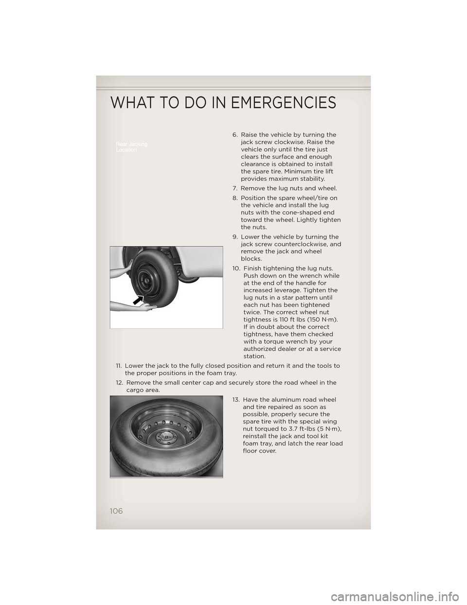
6. Raise the vehicle by turning thejack screw clockwise. Raise the
vehicle only until the tire just
clears the surface and enough
clearance is obtained to install
the spare tire. Minimum tire lift
provides maximum stability.
7. Remove the lug nuts and wheel.
8. Position the spare wheel/tire on the vehicle and install the lug
nuts with the cone-shaped end
toward the wheel. Lightly tighten
the nuts.
9. Lower the vehicle by turning the jack screw counterclockwise, and
remove the jack and wheel
blocks.
10. Finish tightening the lug nuts. Push down on the wrench while
at the end of the handle for
increased leverage. Tighten the
lug nuts in a star pattern until
each nut has been tightened
twice. The correct wheel nut
tightness is 110 ft lbs (150 N·m).
If in doubt about the correct
tightness, have them checked
with a torque wrench by your
authorized dealer or at a service
station.
11. Lower the jack to the fully closed position and return it and the tools to the proper positions in the foam tray.
12. Remove the small center cap and securely store the road wheel in the cargo area.
13. Have the aluminum road wheeland tire repaired as soon as
possible, properly secure the
spare tire with the special wing
nut torqued to 3.7 ft-lbs (5 N·m),
reinstall the jack and tool kit
foam tray, and latch the rear load
floor cover.
WHAT TO DO IN EMERGENCIES
106
Page 110 of 148
WARNING!(Continued)
• Do not let anyone sit in the vehicle when it is on a jack.
• Do not get under the vehicle when it is on a jack.
• Only use the jack in the positions indicated and for lifting thisvehicle during a tire change.
• If working on or near a roadway, be extremely careful of motor traffic.
• To assure that spare tires, flat or inflated, are securely stowed, spares must be stowed with the valve stem facing the ground.
• Carefully follow these tire changing warnings to help prevent personal injury or damage to your vehicle:
• Raising the vehicle higher than necessary can make the vehicle less stable. It could slip off the jack and hurt someone near it. Raise the
vehicle only enough to remove the tire.
• To avoid the risk of forcing the vehicle off the jack, do not tighten the wheel nuts fully until the vehicle has been lowered. Failure to
follow this warning may result in personal injury.
• A loose tire or jack, thrown forward in a collision or hard stop could endanger the occupants of the vehicle. Always stow the jack parts
and the spare tire in the places provided. Have the deflated (flat)
tire repaired or replaced immediately.
BATTERY LOCATION
• The battery in your vehicle is located under the passenger's front seat. Remote battery posts are located on the right side of the engine
compartment for jump-starting.
JUMP-STARTING
• If your vehicle has a discharged battery it can be jump-started using aset of jumper cables and a battery in another vehicle or by using a
portable battery booster pack.
• Jump-starting can be dangerous if done improperly so please follow the procedures in this section carefully.
NOTE: When using a portable battery booster pack follow the
manufacturer’s operating instructions and precautions.
WHAT TO DO IN EMERGENCIES
108
Page 115 of 148
EVENT DATA RECORDER (EDR)
• This vehicle is equipped with an event data recorder (EDR). The mainpurpose of an EDR is to record, in certain crash or near crash-like
situations, such as an air bag deployment or hitting a road obstacle, data
that will assist in understanding how a vehicle’s systems performed. The
EDR is designed to record data related to vehicle dynamics and safety
systems for a short period of time, typically 30 seconds or less. The EDR
in this vehicle is designed to record such data as:
• How various systems in your vehicle were operating;
• Whether or not the driver and passenger safety belts were buckled/fastened;
• How far (if at all) the driver was depressing the accelerator and/or brake pedal; and,
• How fast the vehicle was traveling.
• These data can help provide a better understanding of the circumstances in which crashes and injuries occur.
NOTE: EDR data are recorded by your vehicle only if a non-trivial crash
situation occurs; no data are recorded by the EDR under normal driving
conditions and no personal data (e.g. name, gender, age, and crash location)
are recorded. However, other pa rties, such as law enforcement, could
combine the EDR data with the type of personally identifying data routinely
acquired during a crash investigation.
• To read data recorded by an EDR, special equipment is required, andaccess to the vehicle or the EDR is needed. In addition to the vehicle
manufacturer, other parties such as law enforcement, that have the
special equipment, can read the information if they have access to the
vehicle or the EDR.
WHAT TO DO IN EMERGENCIES
113
Page 123 of 148
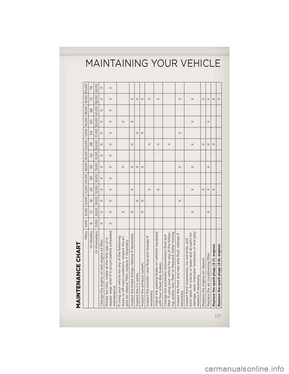
MAINTENANCE CHART
Miles:
8,000 16,000 24,000 32,000 40,000 48,000 56,000 64,000 72,000 80,000 88,000 96,000 104,000
Or Months: 6 12 18 24 30 36 42 48 54 60 66 72 78
Or Kilometers:
13,000 26,000 39,000 52,000 65,000 78,000 91,000 104,000 117,000 130,000 143,000 156,000
169,000
Change the engine oil and engine oil filter. XXXXXXXXXXXXX
Rotate the tires, rotate at the first sign of ir-
regular wear, even if it occurs before scheduled
maintenance. XXXXXXXXXXXXX
If using your vehicle for any of the following:
dusty or off-road conditions. Inspect the en-
gine air cleaner filter; replace if necessary. XXX
Inspect the brake linings; replace if necessary. XXXXXX
InspecttheCVjoints. XXXX
Inspecttheexhaustsystem. XXXXX
Inspect the transfer case fluid and change if
necessary. XXX
Adjust the parking brake on vehicles equipped
with four wheel disc brakes. XXX
Change the automatic transmission fluid and
filter if using your vehicle for any of the follow-
ing: police, taxi, fleet or frequent trailer towing. X
Inspect the front and rear axle fluid, change if
necessary. XXXX
Inspect front suspension, tie rod ends, and
boot seals, for cracks or leaks and all parts for
damage, wear, improper looseness or end play;
replace if necessary. XXXXXX
Replace the engine air cleaner. X X X
Replace the air conditioning filter. XXXXXX
Replace the spark plugs (5.7L engine) XXX
Replace the spark plugs (3.6L engine) X
MAINTAINING YOUR VEHICLE
121
Page 126 of 148
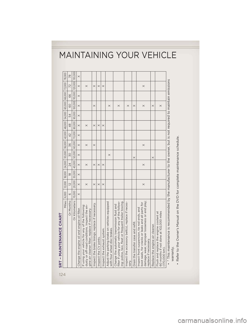
SRT – MAINTENANCE CHART
Miles:
6,000 12,000 18,000 24,000 30,000 36,000 42,000 48,000 54,000 60,000 66,000 72,000 78,000
Or Months: 6 12 18 24 30 36 42 48 54 60 66 72 78
Or Kilometers:
10,000 20,000 30,000 40,000 50,000 60,000 70,000 80,000 90,000 100,000 110,000 120,000 130,000
Change the engine oil and engine oil filter. XXXXXXXXXXXXX
If using your vehicle for any of the following:
dusty or off-road conditions. Inspect the en-
gine air cleaner filter; replace if necessary. XXXX X
Inspect the brake linings; replace if necessary. X X XXXX
Inspect the CV joints. X X X X
Inspect the exhaust system. X X X X
Adjust the parking brake on vehicles equipped
with four wheel disc brakes. XX
Change the automatic transmission fluid and
filter if using your vehicle for any of the follow-
ing: police, taxi, fleet or frequent trailer towing. X
Inspect the accessory belt(s), replace if neces-
sary. X
Drain the transfer case and refill. X X
Inspect front suspension, tie rod ends, and
boot seals, for cracks or leaks and all parts for
damage, wear, improper looseness or end play;
replace if necessary. XXX XX
Replace the engine air cleaner. X X
Flush and replace the engine coolant at
60 months if not done at 102,000 miles
(170,000 km). X• * This maintenance is recommended by the manufacturer to the owner, but is not required to maintain emissions
warranty.
• Refer to the Owner's Manual on the DVD for complete maintenance schedule.
MAINTAINING YOUR VEHICLE
124
Page 129 of 148
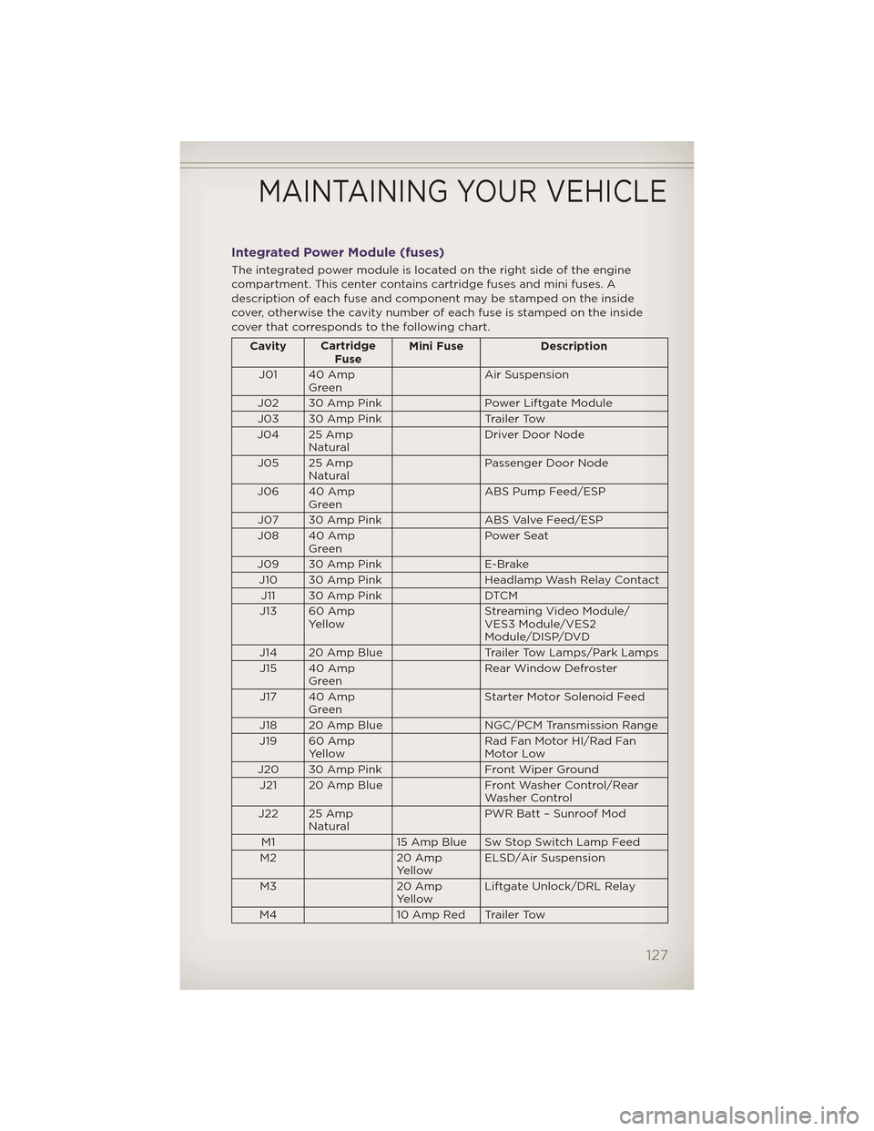
Integrated Power Module (fuses)
The integrated power module is located on the right side of the engine
compartment. This center contains cartridge fuses and mini fuses. A
description of each fuse and component may be stamped on the inside
cover, otherwise the cavity number of each fuse is stamped on the inside
cover that corresponds to the following chart.
CavityCartridge
Fuse Mini Fuse Description
J01 40 Amp Green Air Suspension
J02 30 Amp Pink Power Liftgate Module
J03 30 Amp Pink Trailer Tow
J04 25 Amp Natural Driver Door Node
J05 25 Amp Natural Passenger Door Node
J06 40 Amp Green ABS Pump Feed/ESP
J07 30 Amp Pink ABS Valve Feed/ESP
J08 40 Amp Green Power Seat
J09 30 Amp Pink E-Brake
J10 30 Amp Pink Headlamp Wash Relay Contact
J11 30 Amp Pink DTCM
J13 60 Amp Yellow Streaming Video Module/
VES3 Module/VES2
Module/DISP/DVD
J14 20 Amp Blue Trailer Tow Lamps/Park Lamps
J15 40 Amp Green Rear Window Defroster
J17 40 Amp Green Starter Motor Solenoid Feed
J18 20 Amp Blue NGC/PCM Transmission Range
J19 60 Amp Yellow Rad Fan Motor HI/Rad Fan
Motor Low
J20 30 Amp Pink Front Wiper Ground
J21 20 Amp Blue Front Washer Control/Rear
Washer Control
J22 25 Amp Natural PWR Batt – Sunroof Mod
M1 15 Amp Blue Sw Stop Switch Lamp Feed
M2 20 Amp
Yellow ELSD/Air Suspension
M3 20 Amp
Yellow Liftgate Unlock/DRL Relay
M4 10 Amp Red Trailer Tow
MAINTAINING YOUR VEHICLE
127