fuel JEEP GRAND CHEROKEE 2014 WK2 / 4.G Owner's Manual
[x] Cancel search | Manufacturer: JEEP, Model Year: 2014, Model line: GRAND CHEROKEE, Model: JEEP GRAND CHEROKEE 2014 WK2 / 4.GPages: 220, PDF Size: 6.12 MB
Page 116 of 220
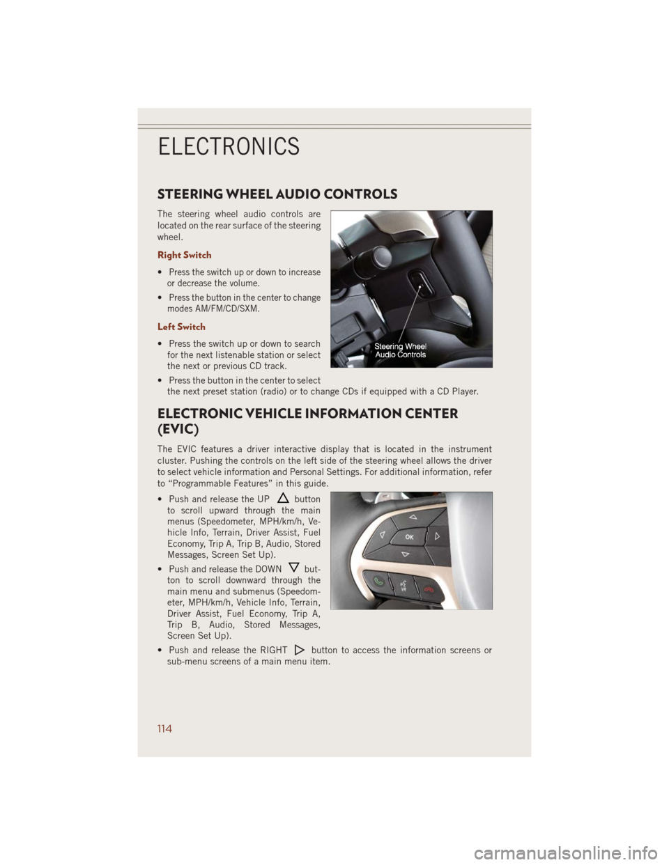
STEERING WHEEL AUDIO CONTROLS
The steering wheel audio controls are
located on the rear surface of the steering
wheel.
Right Switch
•Press the switch up or down to increase
or decrease the volume.
•Press the button in the center to change
modes AM/FM/CD/SXM.
Left Switch
• Press the switch up or down to search
for the next listenable station or select
the next or previous CD track.
• Press the button in the center to select
the next preset station (radio) or to change CDs if equipped with a CD Player.
ELECTRONIC VEHICLE INFORMATION CENTER
(EVIC)
The EVIC features a driver interactive display that is located in the instrument
cluster. Pushing the controls on the left side of the steering wheel allows the driver
to select vehicle information and Personal Settings. For additional information, refer
to “Programmable Features” in this guide.
• Push and release the UP
button
to scroll upward through the main
menus (Speedometer, MPH/km/h, Ve-
hicle Info, Terrain, Driver Assist, Fuel
Economy, Trip A, Trip B, Audio, Stored
Messages, Screen Set Up).
• Push and release the DOWN
but-
ton to scroll downward through the
main menu and submenus (Speedom-
eter, MPH/km/h, Vehicle Info, Terrain,
Driver Assist, Fuel Economy, Trip A,
Trip B, Audio, Stored Messages,
Screen Set Up).
• Push and release the RIGHT
button to access the information screens or
sub-menu screens of a main menu item.
ELECTRONICS
114
Page 117 of 220
• Push the BACK/LEFTbutton to access the information screens or sub-menu
screens of a main menu item.
• Push theOKbutton to access/select the information screens or sub-menu screens
of a main menu item. Push and hold the OK button for two seconds to reset
displayed/selected features that can be reset.
Compass Calibration
This compass is self-calibrating, which eliminates the need to set the compass
manually. When the vehicle is new, the compass may appear erratic and the EVIC will
display “– –” until the compass is calibrated.
You may also calibrate the compass by completing one or more 360 degree turns (in
an area free from large metal or metallic objects) until the “– –” message displayed
in the EVIC turns off. The compass will now function normally.
PROGRAMMABLE FEATURES
EVIC Programmable Features
The EVIC can be used to view or change the following settings. Push the UPor
DOWN
button until System Setup displays, then push the RIGHTbutton.
Scroll through the settings using the UP or DOWN buttons. Push the OK button to
change the setting. Push the BACK/LEFT
button to scroll back to a previous
menu or sub menu.
• Radio Info • Trip Info
• Fuel Economy Info • Tire Pressure
• Cruise Control Info • Vehicle Info
• Digital Vehicle Speed • Stored Warning Messages
• Screen Setup
Uconnect® Customer Programmable Features
• The Uconnect®system allows you to access Customer Programmable feature
settings such as Display, Clock, Safety/Assistance, Lights, Doors & Locks, Auto-On
Comfort & Remote Start, Engine Off Operation, Compass Settings, Audio, Trailer
Brake, Phone/Bluetooth
®, Suspension and SiriusXM Setup and System Informa-
tion through soft-keys.
ELECTRONICS
115
Page 118 of 220
• Touch the “Controls” or “Apps” soft-key located near the bottom of the screen,
then touch the “settings” soft-key to access the Settings screen. When making a
selection, scroll up or down until the preferred setting is highlighted, then press
and release the preferred setting until a check-mark appears next to the setting,
showing that setting has been selected. The following feature settings are
available:
• Display • Clock
• Safety & Driving Assistance • Doors & Locks
• Auto-On Comfort • Engine Off Options
• Compass (Uconnect
®5.0) • Audio
• Phone/Bluetooth®• SiriusXM Setup
• Lights • Trailer Brake
• Suspension • System Information
• Units • Voice
NOTE:
Depending on the vehicles options, feature settings may vary.
EVIC Reconfigurable Screen Setup
The following settings allow you to change what information is displayed in the
instrument cluster as well as the location that information is displayed.
Trip A
• Press and release the UP or DOWN arrow button until the Trip A icon is highlighted
in the EVIC (Toggle left or right to select Trip A or Trip B). Press and release the OK
button to display the Trip A information.
Trip B
• Press and release the UP or DOWN arrow button until the Trip B icon is highlighted
in the EVIC (Toggle left or right to select Trip A or Trip B). Press and release the OK
button to display the Trip B information.
Fuel Economy
• Press and release the UP or DOWN arrow button until the Fuel Economy icon is
highlighted. Press the RIGHT arrow button and the next screen will display the
following:
• Average Fuel Economy/Miles Per Gallon (MPG Bargraph)
• Range To Empty (RTE)
• Current Miles Per Gallon (MPG)
ELECTRONICS
116
Page 144 of 220
DIESEL ENGINE BREAK-IN RECOMMENDATIONS
The diesel engine does not require a break-in period due to its construction. Normal
operation is allowed, providing the following recommendations are followed:
• Warm up the engine before placing it under load.
• Do not operate the engine at idle for prolonged periods.
• Use the appropriate transmission gear to prevent engine lugging.
• Observe vehicle oil pressure and temperature indicators.
• Check the coolant and oil levels frequently.
• Vary throttle position at highway speeds when carrying or towing significant
weight.
NOTE:
Light duty operation such as light trailer towing or no load operation will extend the
time before the engine is at full efficiency. Reduced fuel economy and power may be
seen at this time.
The engine oil installed in the engine at the factory is a high-quality energy conserving
type lubricant. Oil changes should be consistent with anticipated climate conditions
under which vehicle operations will occur. NON-DETERGENT OR STRAIGHT MINERAL
OILS MUST NEVER BE USED.
DIESEL ENGINE STARTING PROCEDURES
Normal Starting Procedure
1. Apply the parking brake.
2. Ensure the shift lever is in the PARK position.
3. Press and hold the brake pedal while pressing the ENGINE START/STOP button
once.
4. The system will take over and attempt to start the vehicle. If the vehicle fails to
start, the starter will disengage automatically after 30 seconds.
5. If you wish to stop the cranking of the engine prior to the engine starting, press the
button again.
6. Check that the oil pressure warning light has turned off.
7. Release the parking brake.
NOTE:
A delay of the start-up can be as long as five seconds under very cold conditions. The
"Wait to Start" telltale will be illuminated during the pre-heat process and the start
will commence upon the telltale going out.
DIESEL
142
Page 145 of 220
CAUTION!
If the “Water in Fuel Indicator Light” remains on, DO NOT START the engine
before you drain the water from the fuel filters to avoid engine damage. Refer to
“Maintenance Procedures/Draining Fuel/Water Separator Filter” in “Maintaining
Your Vehicle” in your Diesel Supplement on the DVD for further information.
Extreme Cold Weather
• The engine block heater is a resistance heater installed in the water jacket of the
engine. It requires a 110–115 Volt AC electrical outlet with a grounded, three-wire
extension cord.
• Its use is recommended for environments that routinely fall below -10°F. It should
be used when the vehicle has not been running overnight or longer periods and
should be plugged in two hours prior to start. Its use is required for cold starts with
temperatures under -20°F.
• A 12 Volt heater built into the fuel filter housing aids in preventing fuel gelling. It
is controlled by a built-in thermostat.
• A Diesel Pre-Heat system both improves engine starting and reduces the amount
of white smoke generated by a warming engine.
NOTE:
The engine block heater cord is a factory installed option. If your vehicle is not
equipped, heater cords are available from your authorized MOPAR
®dealer.
Water In Fuel Message
If a Water In Fuel message orindicator appears in the cluster and a chime
sounds five times, the fuel/water separator will need to be drained immediately to
prevent engine damage.
Refer to “Draining Fuel Water Separator” in this guide for draining instructions or see
your dealer.
DIESEL
143
Page 146 of 220
DIESEL FUEL FILTERS/WATER SEPARATOR
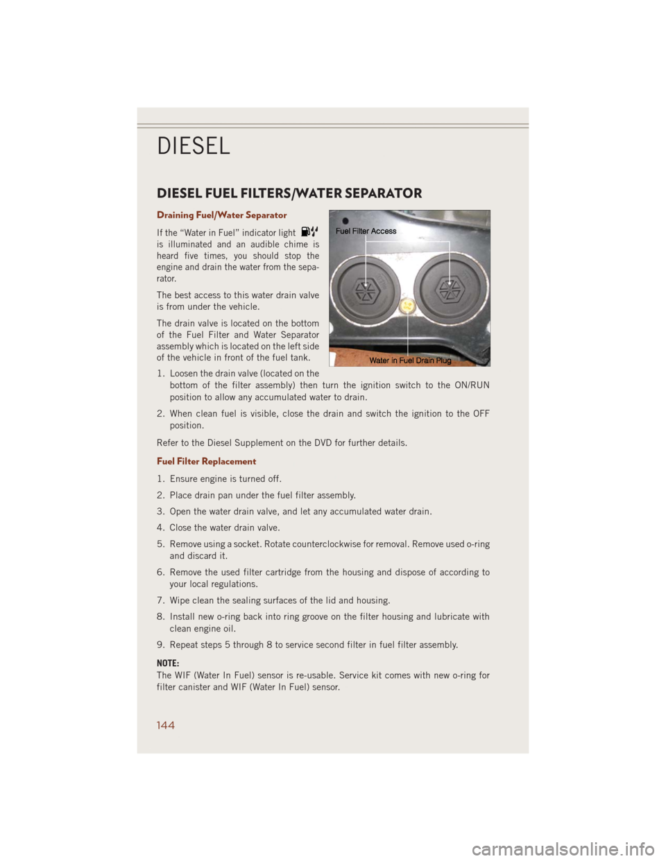
Draining Fuel/Water Separator
If the “Water in Fuel” indicator light
is illuminated and an audible chime is
heard five times, you should stop the
engine and drain the water from the sepa-
rator.
The best access to this water drain valve
is from under the vehicle.
The drain valve is located on the bottom
of the Fuel Filter and Water Separator
assembly which is located on the left side
of the vehicle in front of the fuel tank.
1. Loosen the drain valve (located on the
bottom of the filter assembly) then turn the ignition switch to the ON/RUN
position to allow any accumulated water to drain.
2. When clean fuel is visible, close the drain and switch the ignition to the OFF
position.
Refer to the Diesel Supplement on the DVD for further details.
Fuel Filter Replacement
1. Ensure engine is turned off.
2. Place drain pan under the fuel filter assembly.
3. Open the water drain valve, and let any accumulated water drain.
4. Close the water drain valve.
5. Remove using a socket. Rotate counterclockwise for removal. Remove used o-ring
and discard it.
6. Remove the used filter cartridge from the housing and dispose of according to
your local regulations.
7. Wipe clean the sealing surfaces of the lid and housing.
8. Install new o-ring back into ring groove on the filter housing and lubricate with
clean engine oil.
9. Repeat steps 5 through 8 to service second filter in fuel filter assembly.
NOTE:
The WIF (Water In Fuel) sensor is re-usable. Service kit comes with new o-ring for
filter canister and WIF (Water In Fuel) sensor.
DIESEL
144
Page 147 of 220
CAUTION!
• Diesel fuel will damage blacktop paving surfaces. Drain the filter into an
appropriate container.
•
Do not prefill the fuel filter when installing a new fuel filter. There is a possibility
debris could be introduced into the fuel filter during this action. It is best to install
the filter dry and allow the in-tank lift pump to prime the fuel system.
• If the “Water In Fuel Indicator Light” remains on, DO NOT START the engine
before you drain water from the fuel filter to avoid engine damage.
EXHAUST REGENERATION
This engine meets all required EPA diesel engine emissions standards. To achieve
these emissions standards, your vehicle is equipped with a state-of-the-art engine
and exhaust system. These systems are seamlessly integrated into your vehicle and
managed by the Powertrain Control Module (PCM). Additionally, your vehicle has the
ability to alert you to additional maintenance required on your vehicle or engine.
Refer to the following messages that may be displayed on your Electronic Vehicle
Information Center (EVIC).
Perform Service
Your vehicle will require emissions maintenance at a set interval. To help remind you
when this maintenance is due, the Electronic Vehicle Information Center (EVIC) will
display “Perform Service”.
When the “Perform Service” message is displayed on the EVIC it is necessary to have
the emissions maintenance performed.
Exhaust System — Regeneration Required Now
This message Indicates that the Diesel Particulate Filter (DPF) reached 80% of its
maximum storage capacity.
By simply driving your vehicle at highway speeds for up to 20 minutes, you can
remedy the condition in the particulate filter system and allow your diesel engine and
exhaust after-treatment system to cleanse the filter to remove the trapped PM and
restore the system to normal operating condition.
Exhaust System — Regeneration in Process Exhaust Filter XX% Full
Indicates that the Diesel Particulate Filter (DPF) is self-cleaning. Maintain your
current driving condition until regeneration is completed.
Exhaust System — Regeneration Completed
This message indicates that the Diesel Particulate Filter (DPF) self-cleaning is
completed. If this message is displayed, you will hear one chime to assist in alerting
you of this condition.
DIESEL
145
Page 149 of 220
System Overview
This vehicle is equipped with a Diesel Exhaust Fluid (DEF) injection system and a
Selective Catalytic Reduction (SCR) catalyst to meet the emission requirements.
The DEF injection system consists of the following components:
• DEF tank
• DEF pump
• DEF injector
• Electronically-heated DEF lines• NOx sensors
• Temperature sensors
• SCR catalyst
The DEF injection system and SCR catalyst enable the achievement of diesel
emissions requirements; while maintaining outstanding fuel economy, drivability,
torque and power ratings.
NOTE:
• Your vehicle is equipped with a DEF injection system. You may occasionally hear
an audible clicking noise. This is normal operation.
• The DEF pump will run for a period of time after engine shutdown to purge the DEF
system. This is normal operation.
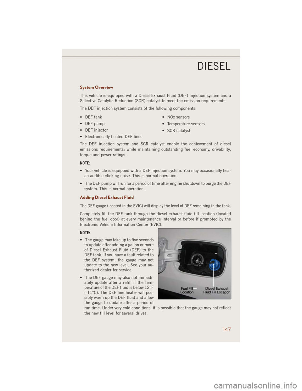
Adding Diesel Exhaust Fluid
The DEF gauge (located in the EVIC) will display the level of DEF remaining in the tank.
Completely fill the DEF tank through the diesel exhaust fluid fill location (located
behind the fuel door) at every maintenance interval or before if prompted by the
Electronic Vehicle Information Center (EVIC).
NOTE:
• The gauge may take up to five seconds
to update after adding a gallon or more
of Diesel Exhaust Fluid (DEF) to the
DEF tank. If you have a fault related to
the DEF system, the gauge may not
update to the new level. See your au-
thorized dealer for service.
• The DEF gauge may also not immedi-
ately update after a refill if the tem-
perature of the DEF fluid is below 12°F
(-11°C). The DEF line heater will pos-
sibly warm up the DEF fluid and allow
the gauge to update after a period of
run time. Under very cold conditions, it is possible that the gauge may not reflect
the new fill level for several drives.
DIESEL
147
Page 152 of 220
ROADSIDE ASSISTANCE
Dial toll-free 1-800-521-2779 for U.S. Residents or 1-800-363-4869 for Canadian
Residents.
• Provide your name, vehicle identification number, license plate number, and your
location, including the telephone number from which you are calling.
• Briefly describe the nature of the problem and answer a few simple questions.
• You will be given the name of the service provider and an estimated time of arrival.
If you feel you are in an “unsafe situation”, please let us know. With your consent,
we will contact local police or safety authorities.
INSTRUMENT CLUSTER WARNING LIGHTS
- Tire Pressure Monitoring System (TPMS) Light
Each tire, including the spare (if provided), should be checked monthly, when cold
and inflated to the inflation pressure recommended by the vehicle manufacturer on
the vehicle placard or tire inflation pressure label. (If your vehicle has tires of a
different size than the size indicated on the vehicle placard or tire inflation pressure
label, you should determine the proper tire inflation pressure for those tires.)
As an added safety feature, your vehicle has been equipped with a Tire Pressure
Monitoring System (TPMS) which display in the Electronic Vehicle Information
Center (EVIC) when one or more of your tires is significantly under-inflated.
Accordingly, when the low tire pressure EVIC display illuminates, you should stop and
check your tires as soon as possible, and inflate them to the proper pressure. Driving
on a significantly under-inflated tire causes the tire to overheat and can lead to tire
failure. Under-inflation also reduces fuel efficiency and tire tread life, and may affect
the vehicle’s handling and stopping ability.
IF THE LIGHT STARTS FLASHING INDICATING A LOW TIRE PRESSURE, ADJUST THE AIR
PRESSURE IN THE LOW TIRE TO THE AIR PRESSURE SHOWN ON THE VEHICLE PLACARD OR
TIRE INFLATION PRESSURE LABEL LOCATED ON THE DRIVER'S DOOR.
NOTE:
After inflation, the vehicle may need to be driven for 20 minutes before the flashing light
will turn off.
WHAT TO DO IN EMERGENCIES
150
Page 155 of 220
- Malfunction Indicator Light (MIL)
The Malfunction Indicator Light (MIL) is part of an onboard diagnostic system called
OBD II that monitors engine and automatic transmission control systems. The light
will illuminate when the key is in the ON/RUN position before engine start. If the bulb
does not come on when turning the key from OFF to ON/RUN, have the condition
checked promptly.
Certain conditions, poor fuel quality, etc., may illuminate the light after engine start.
The vehicle should be serviced if the light stays on through several of your typical
driving cycles. In most situations, the vehicle will drive normally and will not require
towing.
CAUTION!
Prolonged driving with the Malfunction Indicator Light (MIL) on could cause
damage to the engine control system. It also could affect fuel economy and
driveability. If the MIL is flashing, severe catalytic converter damage and power
loss will soon occur. Immediate service is required.
WARNING!
A malfunctioning catalytic converter, as referenced above, can reach higher tempera-
tures than in normal operating conditions. This can cause a fire if you drive slowly or
park over flammable substances such as dry plants, wood, cardboard, etc. This could
result in death or serious injury to the driver, occupants or others.
- Electronic Stability Control (ESC) Activation/Malfunction Indicator Light
The “ESC Activation/Malfunction Indicator Light” in the instrument cluster will
come on when the ignition switch is turned to the ON/RUN position. It should go out
with the engine running. If the “ESC Activation/Malfunction Indicator Light” comes
on continuously with the engine running, a malfunction has been detected in the
ESC system. If this light remains on after several ignition cycles, and the vehicle has
been driven several miles (kilometers) at speeds greater than 30 mph (48 km/h), see
your authorized dealer as soon as possible to have the problem diagnosed and
corrected.
NOTE:
• The “ESC Off Indicator Light” and the “ESC Activation/Malfunction Indicator
Light” come on momentarily each time the ignition switch is turned to ON/RUN.
• Each time the ignition is turned to ON/RUN, the ESC system will be ON, even if
it was turned off previously.
WHAT TO DO IN EMERGENCIES
153