JEEP GRAND CHEROKEE 2015 WK2 / 4.G Owners Manual
Manufacturer: JEEP, Model Year: 2015, Model line: GRAND CHEROKEE, Model: JEEP GRAND CHEROKEE 2015 WK2 / 4.GPages: 717, PDF Size: 18.54 MB
Page 471 of 717
apparent, and/or the system is not functioning as antici-
pated. Coordinate inspection efforts through an autho-
rized dealer.
CAUTION!
Do not use chemical flushes in your power steering
system as the chemicals can damage your power
steering components. Such damage is not covered by
the New Vehicle Limited Warranty.
WARNING!
Fluid level should be checked on a level surface and
with the engine off to prevent injury from moving
parts and to ensure accurate fluid level reading. Do
not overfill. Use only manufacturer’s recommended
power steering fluid.
If necessary, add fluid to restore to the proper indicated
level. With a clean cloth, wipe any spilled fluid from all
surfaces. Refer to “Fluids, Lubricants, and Genuine
Parts” in “Maintaining Your Vehicle” for further informa-
tion.
FUEL SAVER TECHNOLOGY 5.7L ENGINE ONLY
— IF EQUIPPED
This feature offers improved fuel economy by shutting
off four of the engine’s eight cylinders during light load
and cruise conditions. The system is automatic with no
driver inputs or additional driving skills required.
NOTE:This system may take some time to return to full
functionality after a battery disconnect.
PARKING BRAKE
Before leaving the vehicle, make sure that the parking
brake is fully applied and place the shift lever in the
PARK position.
5
STARTING AND OPERATING 469
Page 472 of 717
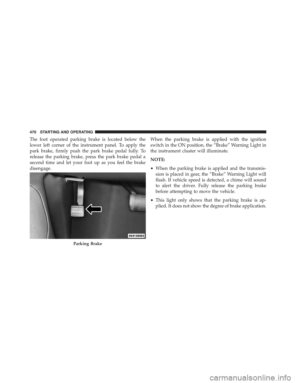
The foot operated parking brake is located below the
lower left corner of the instrument panel. To apply the
park brake, firmly push the park brake pedal fully. To
release the parking brake, press the park brake pedal a
second time and let your foot up as you feel the brake
disengage.
When the parking brake is applied with the ignition
switch in the ON position, the “Brake” Warning Light in
the instrument cluster will illuminate.
NOTE:
•When the parking brake is applied and the transmis-
sion is placed in gear, the “Brake” Warning Light will
flash. If vehicle speed is detected, a chime will sound
to alert the driver. Fully release the parking brake
before attempting to move the vehicle.
•This light only shows that the parking brake is ap-
plied. It does not show the degree of brake application.
Parking Brake
470 STARTING AND OPERATING
Page 473 of 717
When parking on a hill, it is important to turn the front
wheels toward the curb on a downhill grade and away
from the curb on an uphill grade. Apply the parking
brake before placing the shift lever in PARK, otherwise
the load on the transmission locking mechanism may
make it difficult to move the shift lever out of PARK. The
parking brake should always be applied whenever the
driver is not in the vehicle.
WARNING!
•Never use the PARK position as a substitute for the
parking brake. Always apply the parking brake
fully when parked to guard against vehicle move-
ment and possible injury or damage.
•When leaving the vehicle, always remove the Key
Fob from the ignition and lock your vehicle.
(Continued)
WARNING!(Continued)
•Never leave children alone in a vehicle, or with
access to an unlocked vehicle. Allowing children to
be in a vehicle unattended is dangerous for a
number of reasons. A child or others could be
seriously or fatally injured. Children should be
warned not to touch the parking brake, brake pedal
or the shift lever.
•When leaving the vehicle, always make sure the
keyless ignition node is in the “OFF” mode, re-
move the Key Fob from the vehicle and lock the
vehicle.
(Continued)
5
STARTING AND OPERATING 471
Page 474 of 717
WARNING!(Continued)
•Do not leave the Key Fob in or near the vehicle or
in a location accessible to children, and do not
leave the ignition of a vehicle equipped with
Keyless Enter-N-Go™ in the ACC or ON/RUN
mode. A child could operate power windows, other
controls, or move the vehicle.
•Be sure the parking brake is fully disengaged
before driving; failure to do so can lead to brake
failure and a collision.
•Always fully apply the parking brake when leav-
ing your vehicle, or it may roll and cause damage or
injury. Also be certain to leave the transmission in
PARK. Failure to do so may allow the vehicle to roll
and cause damage or injury.
CAUTION!
If the “Brake” Warning Light remains on with the
parking brake released, a brake system malfunction
is indicated. Have the brake system serviced by an
authorized dealer immediately.
BRAKE SYSTEM
Your vehicle is equipped with dual hydraulic brake
systems. If either of the two hydraulic systems loses
normal capability, the remaining system will still func-
tion. However, there will be some loss of overall braking
effectiveness. You may notice increased pedal travel
during application, greater pedal force required to slow
or stop, and potential activation of the “Brake System
Warning Light.”
472 STARTING AND OPERATING
Page 475 of 717
In the event power assist is lost for any reason (i.e.,
repeated brake applications with the engine off) the
brakes will still function. However, the effort required to
brake the vehicle will be much greater than that required
with the power system operating.
ELECTRONIC BRAKE CONTROL SYSTEM
Your vehicle is equipped with an advanced electronic
brake control system that includes the Anti-Lock Brake
System (ABS), Traction Control System (TCS), Brake
Assist System (BAS), Electronic Roll Mitigation (ERM),
and Electronic Stability Control (ESC). All five of these
systems work together to enhance vehicle stability and
control in various driving conditions.
Also, your vehicle may be equipped with Trailer Sway
Control (TSC), Hill Start Assist (HSA), Ready Alert
Braking (RAB), Rain Brake Support (RBS) and, if it has
four-wheel drive with the MP 3023 two-speed transfer
case, Hill Descent Control (HDC), Selec Speed Control
(SSC).
Anti-Lock Brake System (ABS)
The Anti-Lock Brake System (ABS) is designed to aid the
driver in maintaining vehicle control under adverse
braking conditions. The system operates with a separate
computer to modulate hydraulic pressure to prevent
wheel lock-up and help avoid skidding on slippery
surfaces.
All vehicle wheels and tires must be the same size and
type, and tires must be properly inflated to produce
accurate signals for the computer.
5
STARTING AND OPERATING 473
Page 476 of 717
WARNING!
Significant over or under-inflation of tires, or mixing
sizes of tires or wheels on the vehicle can lead to loss
of braking effectiveness.
The Anti-Lock Brake System conducts a low speed self-
test at about 12 mph (20 km/h). If for any reason your
foot is on the brake when the vehicle reaches 12 mph
(20 km/h), this check will be delayed until 25 mph
(40 km/h).
The Anti-Lock Brake System pump motor runs during
the self-test, and during an ABS stop, to provide the
regulated hydraulic pressure. The motor pump makes a
low humming noise during operation; this is normal.
WARNING!
•Pumping of the Anti-Lock Brakes will diminish
their effectiveness and may lead to a collision.
Pumping makes the stopping distance longer. Just
press firmly on your brake pedal when you need to
slow down or stop.
•The Anti-Lock Brake System (ABS) cannot prevent
the natural laws of physics from acting on the
vehicle, nor can they increase braking or steering
efficiency beyond that afforded by the condition of
the vehicle brakes and tires or the traction afforded.
•The ABS cannot prevent collisions, including those
resulting from excessive speed in turns, following
another vehicle too closely, or hydroplaning.
•The capabilities of an ABS-equipped vehicle must
never be exploited in a reckless or dangerous
manner which could jeopardize the user’s safety or
the safety of others.
474 STARTING AND OPERATING
Page 477 of 717
CAUTION!
The Anti-Lock Brake System is subject to possible
detrimental effects of electronic interference caused
by improperly installed aftermarket radios or tele-
phones.
NOTE:During severe braking conditions, a pulsing sen-
sation may occur and a clicking noise will be heard. This
is normal, indicating that the Anti-Lock Brake System is
functioning.
Traction Control System (TCS)
This system monitors the amount of wheel spin of each of
the driven wheels. If wheel spin is detected, brake
pressure is applied to the slipping wheel(s) and engine
power is reduced to provide enhanced acceleration and
stability.
A feature of the TCS system, Brake Limited Differential
(BLD), functions similar to a limited-slip differential and
controls the wheel spin across a driven axle. If one wheel
on a driven axle is spinning faster than the other, the
system will apply the brake of the spinning wheel. This
will allow more engine torque to be applied to the wheel
that is not spinning. This feature remains active even if
ESC system is in the “Partial Off” mode. Refer to “Elec-
tronic Stability Control (ESC)” in this section for further
information.
Brake Assist System (BAS)
The BAS is designed to optimize the vehicle’s braking
capability during emergency braking maneuvers. The
system detects an emergency braking situation by sens-
ing the rate and amount of brake application and then
applies optimum pressure to the brakes. This can help
reduce braking distances. The BAS complements the
anti-lock brake system (ABS). Applying the brakes very
5
STARTING AND OPERATING 475
Page 478 of 717
quickly results in the best BAS assistance. To receive the
benefit of the system, you must applycontinuousbrak-
ing pressure during the stopping sequence (do not
“pump” the brakes). Do not reduce brake pedal pressure
unless braking is no longer desired. Once the brake pedal
is released, the BAS is deactivated.
WARNING!
•The BAS cannot prevent the natural laws of phys-
ics from acting on the vehicle, nor can it increase
the traction afforded by prevailing road conditions.
•The BAS cannot prevent collisions, including those
resulting from excessive speed in turns, driving on
very slippery surfaces, or hydroplaning.
•The capabilities of a BAS-equipped vehicle must
never be exploited in a reckless or dangerous
manner which could jeopardize the user’s safety or
the safety of others.
Electronic Roll Mitigation (ERM)
This system anticipates the potential for wheel lift by
monitoring the driver ’s steering wheel input and the
speed of the vehicle. When ERM determines that the rate
of change of the steering wheel angle and vehicle’s speed
are sufficient to potentially cause wheel lift, it then
applies the appropriate brake and may also reduce
engine power to lessen the chance that wheel lift will
occur. ERM will only intervene during very severe or
evasive driving maneuvers.
ERM can only reduce the chance of wheel lift occurring
during severe or evasive driving maneuvers. It cannot
prevent wheel lift due to other factors, such as road
conditions, leaving the roadway, or striking objects or
other vehicles.
476 STARTING AND OPERATING
Page 479 of 717
WARNING!
Many factors, such as vehicle loading, road condi-
tions, and driving conditions, influence the chance
that wheel lift or rollover may occur. ERM cannot
prevent all wheel lift or rollovers, especially those
that involve leaving the roadway or striking objects
or other vehicles. The capabilities of an ERM-
equipped vehicle must never be exploited in a reck-
less or dangerous manner, which could jeopardize
the user’s safety or the safety of others.
Electronic Stability Control (ESC)
This system enhances directional control and stability of
the vehicle under various driving conditions. ESC cor-
rects for oversteering or understeering of the vehicle by
applying the brake of the appropriate wheel to assist in
counteracting the oversteer or understeer condition. En-
gine power may also be reduced to help the vehicle
maintain the desired path.
ESC uses sensors in the vehicle to determine the vehicle
path intended by the driver and compares it to the actual
path of the vehicle. When the actual path does not match
the intended path, ESC applies the brake of the appro-
priate wheel to assist in counteracting the oversteer or
understeer condition.
•Oversteer - when the vehicle is turning more than
appropriate for the steering wheel position.
•Understeer - when the vehicle is turning less than
appropriate for the steering wheel position.
The “ESC Activation/Malfunction Indicator Light” lo-
cated in the instrument cluster will start to flash as soon
as the tires lose traction and the ESC system becomes
active. The “ESC Activation/Malfunction Indicator
Light” also flashes when the TCS is active. If the “ESC
5
STARTING AND OPERATING 477
Page 480 of 717
Activation/Malfunction Indicator Light” begins to flash
during acceleration, ease up on the accelerator and apply
as little throttle as possible. Be sure to adapt your speed
and driving to the prevailing road conditions.
WARNING!
The Electronic Stability Control (ESC) cannot pre-
vent the natural laws of physics from acting on the
vehicle, nor can it increase the traction afforded by
prevailing road conditions. ESC cannot prevent col-
lisions, including those resulting from excessive
speed in turns, driving on very slippery surfaces, or
hydroplaning. ESC also cannot prevent collisions
resulting from loss of vehicle control due to inappro-
priate driver input for the conditions. Only a safe,
attentive, and skillful driver can prevent collisions.
The capabilities of an ESC equipped vehicle must
(Continued)
WARNING!(Continued)
never be exploited in a reckless or dangerous manner
which could jeopardize the user ’s safety or the safety
of others.
The ESC system has two available operating modes in
4WD HIGH range and two-wheel drive vehicles, and one
operating mode in 4WD LOW range.
High Range (Four-Wheel Drive Models) Or
Two-Wheel Drive Models
On
This is the normal operating mode for ESC in 4WD HIGH
range and in two-wheel drive vehicles. Whenever the
vehicle is started or the transfer case (if equipped) is
shifted from 4WD LOW range or NEUTRAL back to
4WD HIGH range, the ESC system will be in this “On”
478 STARTING AND OPERATING