JEEP GRAND CHEROKEE 2015 WK2 / 4.G Owners Manual
Manufacturer: JEEP, Model Year: 2015, Model line: GRAND CHEROKEE, Model: JEEP GRAND CHEROKEE 2015 WK2 / 4.GPages: 717, PDF Size: 18.54 MB
Page 451 of 717
launches, to minimize wheel slippage. If equipped
with air suspension, the default ride height for Snow is
NRH.
•Auto– Fully automatic full time four-wheel drive
operation can be used on and off road. Balances
traction with seamless steering feel to provide im-
proved handling and acceleration over two-wheel
drive vehicles. If equipped with air suspension, the
level will change to NRH.
•Sand– Off road calibration for use on low traction
surfaces such as sand or wet grass. Driveline is maxi-
mized for traction. Some binding may be felt on less
forgiving surfaces. The electronic brake controls are set
to limit traction control management of throttle and
wheel spin. If equipped with air suspension, the
default ride height for Sand is NRH.
•Mud– Off road calibration for use on low traction
surfaces such as mud. Driveline is maximized for
traction. Some binding may be felt on less forgiving
surfaces. The electronic brake controls are set to limit
traction control management of throttle and wheel
spin. If equipped with air suspension, the level will
change to Off Road 1.
•Rock– Off road calibration only available in 4WD Low
range. The vehicle is raised (if equipped with Air
Suspension) for improved ground clearance. Traction
based tuning with improved steer-ability for use on
high traction off-road surfaces. Use for low speed
obstacles such as large rocks, deep ruts, etc. If
equipped with air suspension, the vehicle level will
change to Off-Road 2. If the Selec-Terrain™ switch is in
ROCK mode, and the transfer case is switched from
4WD Low to 4WD High, the Selec-Terrain™ system
will return to AUTO.
5
STARTING AND OPERATING 449
Page 452 of 717
NOTE:Activate the Hill Descent Control or Selec Speed
Control for steep downhill control. See “Electronic Brake
Control System” in this section for further information.
Driver Information Display (DID) Messages
When the appropriate conditions exist, a message will
appear in the DID display. Refer to “Driver Information
Display (DID)” in “Understanding Your Instrument
Panel” for further information.
QUADRA-LIFT™ — IF EQUIPPED
Description
The Quadra-Lift™ air suspension system provides full
time load leveling capability along with the benefit of
vehicle height adjustment by the push of a button.
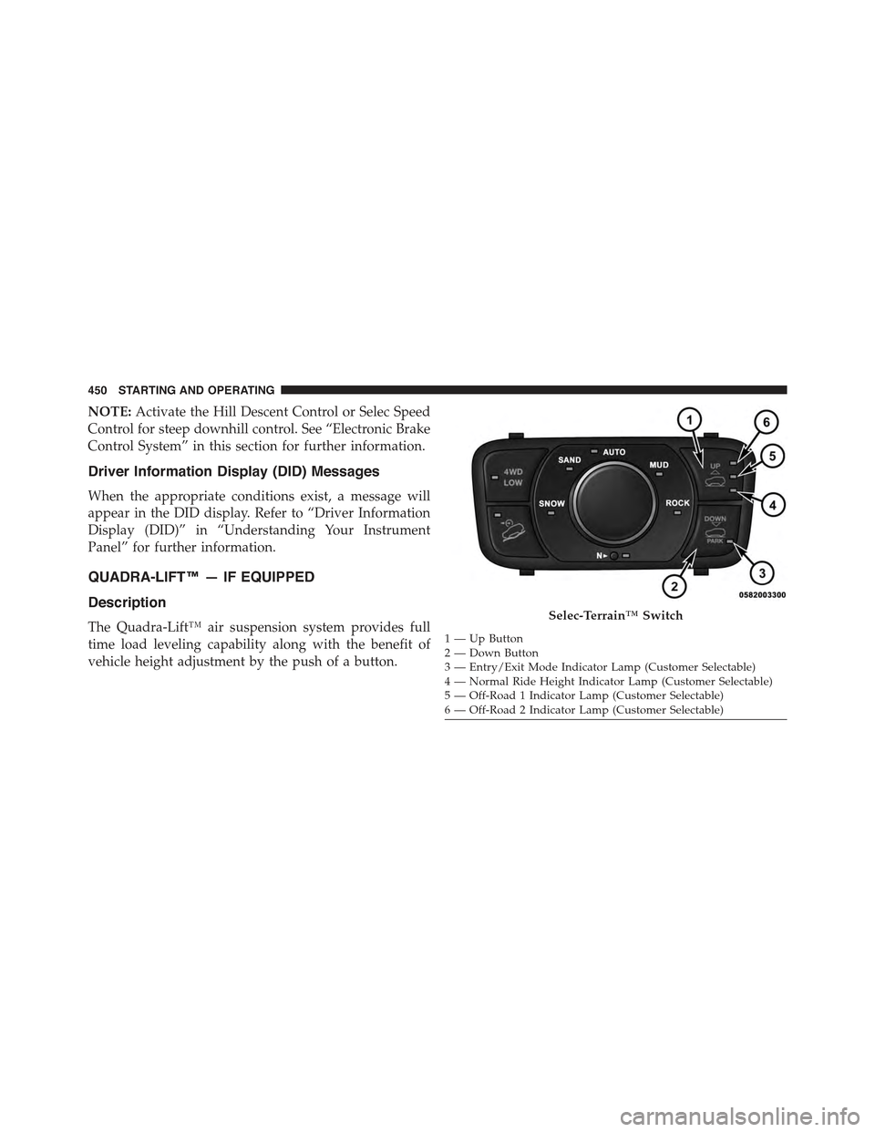
Selec-Terrain™ Switch
1—UpButton2—DownButton3 — Entry/Exit Mode Indicator Lamp (Customer Selectable)4—NormalRideHeightIndicatorLamp(CustomerSelectable)5 — Off-Road 1 Indicator Lamp (Customer Selectable)6 — Off-Road 2 Indicator Lamp (Customer Selectable)
450 STARTING AND OPERATING
Page 453 of 717
•Normal Ride Height (NRH)– This is the standard
position of the suspension and is meant for normal
driving.
•Off-Road 1 (OR1) (Raises the vehicle approximately
1.1 in (28 mm)– This is the primary position for all
off-road driving until OR2 is needed. A smoother and
more comfortable ride will result. Push the “Up”
button once from the NRH position while the vehicle
speed is below 38 mph (61 km/h). When in the OR1
position, if the vehicle speed remains between 40 mph
(64 km/h) and 50 mph (80 km/h) for greater than 20
seconds or if the vehicle speed exceeds 50 mph
(80 km/h), the vehicle will be automatically lowered to
NRH. Refer to “Off-Road Driving Tips” in “Starting
and Operating” for further information.
•Off-Road 2 (OR2) (Raises the vehicle approximately
2.2 in (55 mm)– This position is intended for off-
roading use only where maximum ground clearance is
required. To enter OR2, push the “Up” button twice
from the NRH position or once from the OR1 position
while vehicle speed is below 20 mph (32 km/h). While
in OR2, if the vehicle speed exceeds 25 mph (40 km/h)
the vehicle height will be automatically lowered to
OR1. Refer to “Off-Road Driving Tips” in “Starting
and Operating” for further information.
•Aero Mode (Lowers the vehicle approximately 0.6 in
(15 mm)– This position provides improved aerody-
namics by lowering the vehicle. The vehicle will
automatically enter Aero Mode when the vehicle
speed remains between 52 mph (83 km/h) and 56 mph
(90 km/h) for greater than 20 seconds or if the vehicle
speed exceeds 56 mph (90 km/h). The vehicle will
return to NRH from Aero Mode if the vehicle speed
remains between 20 mph (32 km/h) and 25 mph
(40 km/h) for greater than 20 seconds or if the vehicle
5
STARTING AND OPERATING 451
Page 454 of 717
speed falls below 20 mph (32 km/h). The vehicle will
enter Aero Mode, regardless of vehicle speed if the
shift lever is in the “SPORT” position.
•Entry/Exit Mode (Lowers the vehicle approximately
1.6 in (40 mm)– This position lowers the vehicle for
easier passenger entry and exit as well as lowering the
rear of the vehicle for easier loading and unloading of
cargo. To enter Entry/Exit Mode, push the “Down”
button once from (NRH) while the vehicle speed is
below 25 mph (40 km/h). Once the vehicle speed goes
below 15 mph (24 km/h) the vehicle height will begin
to lower. If the vehicle speed remains between 15 mph
(24 km/h) and 25 mph (40 km/h) for greater than 60
seconds, or the vehicle speed exceeds 25 mph
(40 km/h) the Entry/Exit Mode change will be can-
celled. To exit Entry/Exit Mode, press the “Up” button
once while in Entry/Exit Mode or drive the vehicle
over 15 mph (24 km/h).
NOTE:Automatic lowering of the vehicle into Entry/
Exit Mode can be enabled through the Uconnect® Touch-
Screen Radio. If this feature is enabled, the vehicle will
only lower if the shift lever is in#PARK#, the terrain
switch is in#AUTO#, the transfer-case is in#AUTO” and
the vehicle level should be either in Normal or Aero
Mode. The Vehicle will not automatically lower if the air
suspension level is in Off Rd 2 or Off Rd 1. If the vehicle
is equipped with Intrusion Theft Module (ITM), the
lowering will be suppressed when the ignition is
switched Off and the Door is Open to prevent setting the
alarm Off.
The Selec-Terrain™ switch will automatically change the
vehicle to the proper height based on the position of the
Selec-Terrain™ switch. The height can be changed from
the default Selec-Terrain™ setting by normal use of the
air suspension buttons. Refer to “Selec-Terrain™” in
“Starting and Operating” for further information.
452 STARTING AND OPERATING
Page 455 of 717
The system requires that the engine be running for all
changes. When lowering the vehicle all of the doors,
including the liftgate, must be closed. If a door is opened
at any time while the vehicle is lowering the change will
not be completed until the open door(s) is closed.
The Quadra-Lift™ air suspension system uses a lifting
and lowering pattern which keeps the headlights from
incorrectly shining into oncoming traffic. When raising
the vehicle, the rear of the vehicle will move up first and
then the front. When lowering the vehicle, the front will
move down first and then the rear.
After the engine is turned off, it may be noticed that the
air suspension system operates briefly, this is normal. The
system is correcting the position of the vehicle to ensure
a proper appearance.
To assist with changing a spare tire, the Quadra-Lift™ air
suspension system has a feature which allows the auto-
matic leveling to be disabled. Refer to “Uconnect® Set-
tings” in “Understanding Your Instrument Panel” for
further information.
NOTE:If equipped with a touch screen radio all
enabling/disabling of air suspension features must be
done through the radio. Refer to “Uconnect® Access
Settings” in “Understanding Your Instrument Panel” for
further information.
WARNING!
The air suspension system uses a high pressure
volume of air to operate the system. To avoid per-
sonal injury or damage to the system, see your
authorized dealer for service.
5
STARTING AND OPERATING 453
Page 456 of 717
Air Suspension Modes
The Air Suspension system has multiple modes to protect
the system in unique situations:
Tire/Jack Mode
To assist with changing a spare tire, the air suspension
system has a feature which allows the automatic leveling
to be disabled. Refer to “Uconnect® Settings” in “Under-
standing Your Instrument Panel” for further information.
NOTE:This mode is intended to be enabled with engine
running.
Transport Mode
To assist with flat bed towing, the air suspension system
has a feature which will put the vehicle into Entry/Exit
height and disable the automatic load leveling system.
Refer to “Uconnect® Settings” in “Understanding Your
Instrument Panel” for further information.
NOTE:This mode is intended to be enabled with engine
running.
Wheel Alignment Mode
Before performing a wheel alignment this mode must be
enabled. Refer to “Uconnect® Settings” in “Understand-
ing Your Instrument Panel” for further information.
NOTE:This mode is intended to be enabled with engine
running.
If equipped with a touch screen radio all enabling/
disabling of air suspension features must be done
through the radio. Refer to “Uconnect® Settings” in
“Understanding Your Instrument Panel” for further in-
formation.
454 STARTING AND OPERATING
Page 457 of 717
Driver Information Display (DID) Messages
When the appropriate conditions exist, a message will
appear in the DID display. Refer to “Driver Information
Display (DID)” in “Understanding Your Instrument
Panel” for further information.
Operation
The indicator lamps 3 through 6 will illuminate to show
the current position of the vehicle. Flashing indicator
lamps will show a position which the system is working
to achieve. When raising, if multiple indicator lamps are
flashing on the “Up” button, the highest flashing indica-
tor lamp is the position the system is working to achieve.
When lowering, if multiple indicators are flashing on the
#Up#button the lowest solid indicator lamp is the posi-
tion the system is working to achieve.
Pressing the “UP” button once will move the suspension
one position higher from the current position, assuming
all conditions are met (i.e. engine running, speed below
threshold, etc). The “UP” button can be pressed multiple
times, each press will raise the requested level by one
position up to a maximum position of OR2 or the highest
position allowed based on current conditions (i.e. vehicle
speed, etc).
Pressing the “DOWN” button once will move the sus-
pension one position lower from the current level, as-
suming all conditions are met (i.e. engine running, doors
closed, speed below threshold, etc). The “DOWN” button
can be pressed multiple times. Each press will lower the
requested level by one position down to a minimum of
Park Mode or the lowest position allowed based on
current conditions (i.e. vehicle speed, etc.)
Automatic height changes will occur based on vehicle
speed and the current vehicle height. The indicator lamps
and DID messages will operate the same for automatic
changes and user requested changes.
5
STARTING AND OPERATING 455
Page 458 of 717
•Off-Road 2 (OR2) – Indicator lamps 4, 5, and 6 will be
illuminated when the vehicle is in OR2.
•Off-Road 1 (OR1) – Indicator lamps 4 and 5 will be
illuminated when the vehicle is in OR1.
•Normal Ride Height (NRH) – Indicator lamp 4 will be
illuminated when the vehicle is in this position.
•Entry/Exit Mode – Indicator lamp 3 will be illumi-
nated when the vehicle is in Entry/Exit Mode. If
Entry/Exit Mode is requested while vehicle speed is
between 15 mph (24 km/h) and 25 mph (40 km/h),
indicator lamp 4 will remain on solid and indicator
lamp 3 will flash as the system waits for the vehicle to
reduce speed. If vehicle speed is reduced to, and kept
below, 15 mph (24 km/h) indicator lamp 4 will turn off
and indicator lamp 3 will flash until Entry/Exit Mode
is achieved at which point indicator lamp 3 will go
solid. If during the height change to Entry/Exit Mode,
the vehicle speed exceeds 15 mph (24 km/h), the
height change will be paused until the vehicle speed
either goes below 15 mph (24 km/h) and the height
change continues to Entry/Exit Mode, or exceeds
25 mph (40 km/h) and the vehicle height will return to
NRH. Entry/Exit Mode may be selected while the
vehicle is not moving provided that the engine is still
running and all doors remain closed.
•Transport Mode - No indicator lamps will be illumi-
nated. Customer driving will disable Transport Mode.
•Tire/Jack Mode - indicator lamps 3 and 6 will be
illuminated. Customer driving will disable Tire/Jack
Mode.
•Wheel Alignment Mode - indicator lamps 3 and 4 will
be illuminated. Customer driving will disable Wheel
Alignment Mode.
456 STARTING AND OPERATING
Page 459 of 717
ON-ROAD DRIVING TIPS
Utility vehicles have higher ground clearance and a
narrower track to make them capable of performing in a
wide variety of off-road applications. Specific design
characteristics give them a higher center of gravity than
ordinary cars.
An advantage of the higher ground clearance is a better
view of the road, allowing you to anticipate problems.
They are not designed for cornering at the same speeds as
conventional two-wheel drive vehicles any more than
low-slung sports cars are designed to perform satisfacto-
rily in off-road conditions. If at all possible, avoid sharp
turns or abrupt maneuvers. As with other vehicles of this
type, failure to operate this vehicle correctly may result in
loss of control or vehicle rollover.
OFF-ROAD DRIVING TIPS
NOTE:Prior to off-road driving with non-Summit mod-
els that are also equipped with an Off Road Package,
remove the lower fascia to prevent damage. The lower
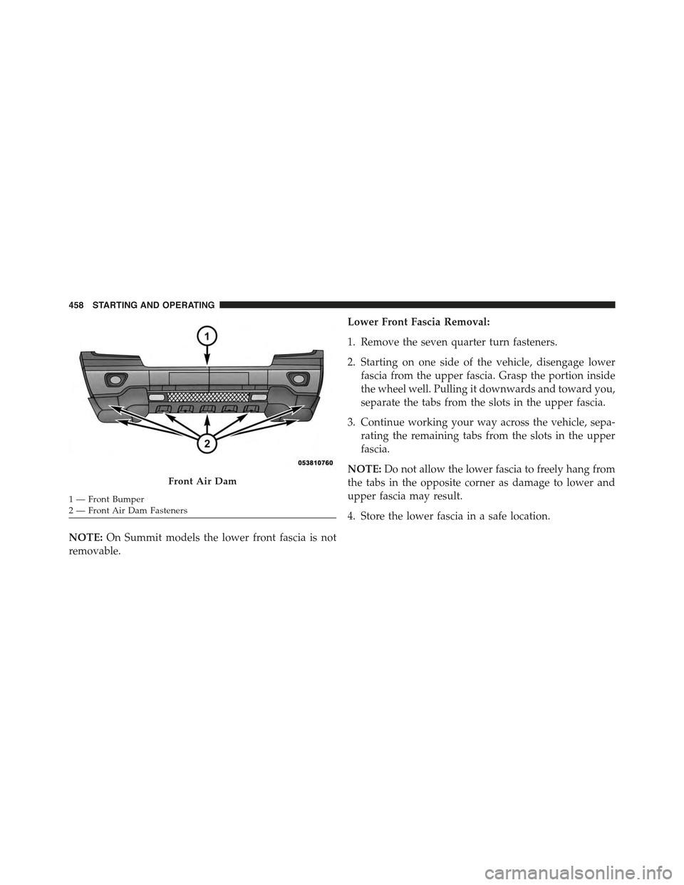
fascia is attached to the lower part of the front fascia with
seven quarter turn fasteners and can be removed by
hand. The front license plate bracket must be removed
first if equipped.
5
STARTING AND OPERATING 457
Page 460 of 717
NOTE:On Summit models the lower front fascia is not
removable.
Lower Front Fascia Removal:
1. Remove the seven quarter turn fasteners.
2. Starting on one side of the vehicle, disengage lower
fascia from the upper fascia. Grasp the portion inside
the wheel well. Pulling it downwards and toward you,
separate the tabs from the slots in the upper fascia.
3. Continue working your way across the vehicle, sepa-
rating the remaining tabs from the slots in the upper
fascia.
NOTE:Do not allow the lower fascia to freely hang from
the tabs in the opposite corner as damage to lower and
upper fascia may result.
4. Store the lower fascia in a safe location.
Front Air Dam
1—FrontBumper2 — Front Air Dam Fasteners
458 STARTING AND OPERATING