lights JEEP GRAND CHEROKEE 2016 WK2 / 4.G Owner's Manual
[x] Cancel search | Manufacturer: JEEP, Model Year: 2016, Model line: GRAND CHEROKEE, Model: JEEP GRAND CHEROKEE 2016 WK2 / 4.GPages: 276, PDF Size: 10.84 MB
Page 129 of 276
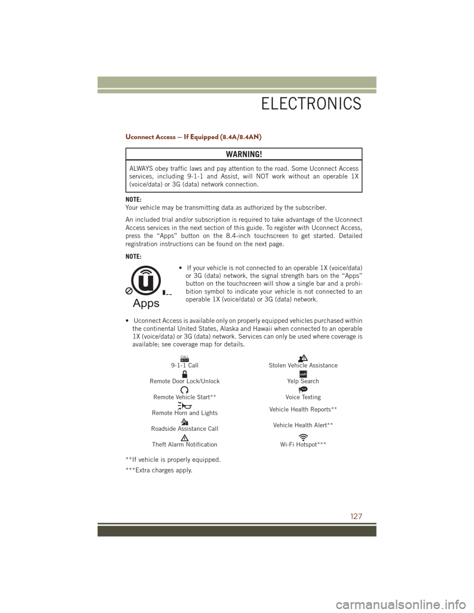
Uconnect Access — If Equipped (8.4A/8.4AN)
WARNING!
ALWAYS obey traffic laws and pay attention to the road. Some Uconnect Access
services, including 9-1-1 and Assist, will NOT work without an operable 1X
(voice/data) or 3G (data) network connection.
NOTE:
Your vehicle may be transmitting data as authorized by the subscriber.
An included trial and/or subscription is required to take advantage of the Uconnect
Access services in the next section of this guide. To register with Uconnect Access,
press the “Apps” button on the 8.4-inch touchscreen to get started. Detailed
registration instructions can be found on the next page.
NOTE: • If your vehicle is not connected to an operable 1X (voice/data)or 3G (data) network, the signal strength bars on the “Apps”
button on the touchscreen will show a single bar and a prohi-
bition symbol to indicate your vehicle is not connected to an
operable 1X (voice/data) or 3G (data) network.
• Uconnect Access is available only on properly equipped vehicles purchased within the continental United States, Alaska and Hawaii when connected to an operable
1X (voice/data) or 3G (data) network. Services can only be used where coverage is
available; see coverage map for details.
CALL9119-1-1 CallStolen Vehicle Assistance
Remote Door Lock/UnlockYelp Search
Remote Vehicle Start**
Text
Voice Texting
Remote Horn and Lights Vehicle Health Reports**
Roadside Assistance Call Vehicle Health Alert**
Theft Alarm NotificationWi-Fi Hotspot***
**If vehicle is properly equipped.
***Extra charges apply.
ELECTRONICS
127
Page 150 of 276
PROGRAMMABLE FEATURES
DID Main Menu Selectable Items
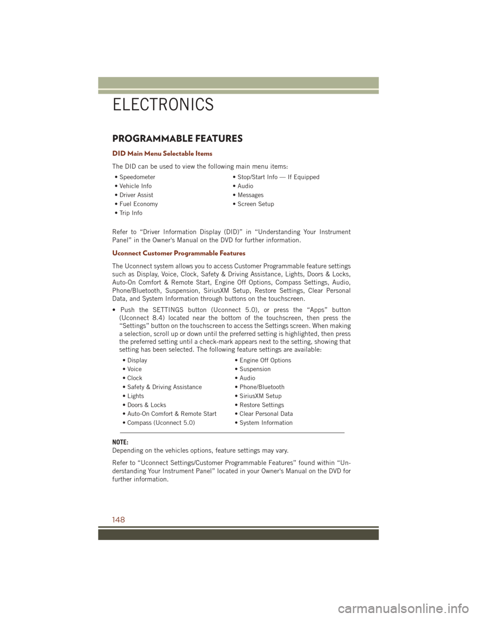
The DID can be used to view the following main menu items:
• Speedometer• Stop/Start Info — If Equipped
• Vehicle Info • Audio
• Driver Assist • Messages
• Fuel Economy • Screen Setup
• Trip Info
Refer to “Driver Information Display (DID)” in “Understanding Your Instrument
Panel” in the Owner's Manual on the DVD for further information.
Uconnect Customer Programmable Features
The Uconnect system allows you to access Customer Programmable feature settings
such as Display, Voice, Clock, Safety & Driving Assistance, Lights, Doors & Locks,
Auto-On Comfort & Remote Start, Engine Off Options, Compass Settings, Audio,
Phone/Bluetooth, Suspension, SiriusXM Setup, Restore Settings, Clear Personal
Data, and System Information through buttons on the touchscreen.
• Push the SETTINGS button (Uconnect 5.0), or press the “Apps” button (Uconnect 8.4) located near the bottom of the touchscreen, then press the
“Settings” button on the touchscreen to access the Settings screen. When making
a selection, scroll up or down until the preferred setting is highlighted, then press
the preferred setting until a check-mark appears next to the setting, showing that
setting has been selected. The following feature settings are available:
• Display • Engine Off Options
• Voice • Suspension
• Clock • Audio
• Safety & Driving Assistance • Phone/Bluetooth
• Lights • SiriusXM Setup
• Doors & Locks • Restore Settings
• Auto-On Comfort & Remote Start • Clear Personal Data
• Compass (Uconnect 5.0) • System Information
NOTE:
Depending on the vehicles options, feature settings may vary.
Refer to “Uconnect Settings/Customer Programmable Features” found within “Un-
derstanding Your Instrument Panel” located in your Owner's Manual on the DVD for
further information.
ELECTRONICS
148
Page 160 of 276
Mud– Off road calibration for use on low traction surfaces such as mud. Driveline is
maximized for traction. Some binding may be felt on less forgiving surfaces. The
electronic brake controls are set to limit traction control management of throttle and
wheel spin. If equipped with air suspension, the level will change to Off-Road 1.
Rock – Off-road calibration only available in 4WD Low range. The vehicle is raised (if
equipped with Air Suspension) for improved ground clearance. Traction based tuning
with improved steer-ability for use on high traction off-road surfaces. Activate the Hill
Descent Control for steep downhill control. Use for low speed obstacles such as large
rocks, deep ruts, etc. If equipped with air suspension, the vehicle level will change
to Off-Road 2. If the Selec-Terrain switch is in ROCK mode, and the transfer case is
switched from 4WD Low to 4WD High, the Selec-Terrain system will return to AUTO.
QUADRA-LIFT
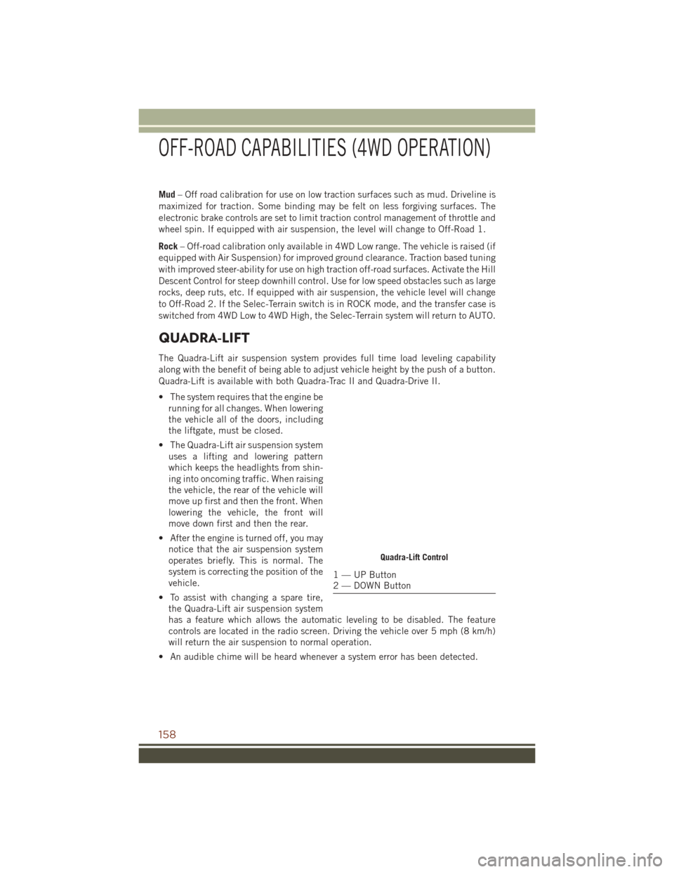
The Quadra-Lift air suspension system provides full time load leveling capability
along with the benefit of being able to adjust vehicle height by the push of a button.
Quadra-Lift is available with both Quadra-Trac II and Quadra-Drive II.
• The system requires that the engine be running for all changes. When lowering
the vehicle all of the doors, including
the liftgate, must be closed.
• The Quadra-Lift air suspension system uses a lifting and lowering pattern
which keeps the headlights from shin-
ing into oncoming traffic. When raising
the vehicle, the rear of the vehicle will
move up first and then the front. When
lowering the vehicle, the front will
move down first and then the rear.
• After the engine is turned off, you may notice that the air suspension system
operates briefly. This is normal. The
system is correcting the position of the
vehicle.
• To assist with changing a spare tire, the Quadra-Lift air suspension system
has a feature which allows the automatic leveling to be disabled. The feature
controls are located in the radio screen. Driving the vehicle over 5 mph (8 km/h)
will return the air suspension to normal operation.
• An audible chime will be heard whenever a system error has been detected.
Quadra-Lift Control
1 — UP Button
2 — DOWN Button
OFF-ROAD CAPABILITIES (4WD OPERATION)
158
Page 172 of 276
13. Push the ENGINE STOP/START button twice (without pressing the brake pedal)to turn the ignition switch to the OFF position.
14. Attach the vehicle to the tow vehicle using a suitable tow bar.
15. Release the parking brake.
NOTE:
• Steps 1 through 4 are requirements that must be met before pressing the NEUTRAL (N) button, and must continue to be met until the shift has been
completed. If any of these requirements are not met before pushing the NEUTRAL
(N) button or are no longer met during the shift, then the NEUTRAL (N) indicator
light will flash continuously until all requirements are met or until the NEUTRAL
(N) button is released.
• The ignition switch must be in the ON/RUN position for a shift to take place and for the position indicator lights to be operable. If the ignition switch is not in the
ON/RUN position, the shift will not take place and no position indicator lights will
be on or flashing.
• A flashing NEUTRAL (N) position indicator light indicates that shift requirements have not been met.
• If the vehicle is equipped with Quadra-Lift air suspension, the engine should be started and left running for a minimum of 60 seconds (with all the doors closed)
at least once every 24 hours. This process allows the air suspension to adjust the
vehicle’s ride height to compensate for temperature effects.
Shifting Out Of NEUTRAL (N)
Use the following procedure to prepare your vehicle for normal usage:
1. Bring the vehicle to a complete stop, leaving it connected to the tow vehicle.
2. Firmly apply the parking brake.
3. Start the engine.
4. Press and hold the brake pedal.
5. Shift the transmission into NEUTRAL.
6. Using a ballpoint pen or similar object, push and hold the recessed transfer case
NEUTRAL (N) button (located by the selector switch) for one second.
7. When the NEUTRAL (N) indicator light turns off, release the NEUTRAL (N) button. After the NEUTRAL (N) button has been released, the transfer case will
shift to the position indicated by the selector switch.
8. Shift the transmission into PARK. Turn the engine OFF.
UTILITY
170
Page 173 of 276
9. Release the brake pedal.
10. Disconnect vehicle from the tow vehicle.
11. Start the engine.
12. Press and hold the brake pedal.
13. Release the parking brake.
14. Shift the transmission into DRIVE, release the brake pedal, and check that thevehicle operates normally.
NOTE:
• Steps 1 through 5 are requirements that must be met prior to pressing the NEUTRAL (N) button, and must continue to be met until the shift has been
completed. If any of these requirements are not met prior to prushing the
NEUTRAL (N) button or are no longer met during the shift, the NEUTRAL (N)
indicator light will flash continuously until all requirements are met or until the
NEUTRAL (N) button is released.
• The ignition switch must be in the ON/RUN position for a shift to take place and for the position indicator lights to be operable. If the ignition switch is not in the
ON/RUN position, the shift will not take place and no position indicator lights will
be on or flashing.
• A flashing NEUTRAL (N) position indicator light indicates that shift requirements have not been met.
UTILITY
171
Page 191 of 276
ROADSIDE ASSISTANCE
Dial toll-free 1-800-521-2779 for U.S. Residents or 1-800-363-4869 for Canadian
Residents.
• Provide your name, vehicle identification number, license plate number, and yourlocation, including the telephone number from which you are calling.
• Briefly describe the nature of the problem and answer a few simple questions.
• You will be given the name of the service provider and an estimated time of arrival. If you feel you are in an “unsafe situation”, please let us know. With your consent,
we will contact local police or safety authorities.
INSTRUMENT CLUSTER WARNING LIGHTS
– Battery Charge Warning Light
This light illuminates when the battery is not charging properly. If the battery charge
warning light remains on, it means that the vehicle is experiencing a problem with the
charging system.
We recommend you do not continue driving if it is on. Have the vehicle serviced
immediately.
– Oil Pressure Warning Light
This light indicates low engine oil pressure. If the light turns on while driving, stop
the vehicle and shut off the engine as soon as possible. A chime will sound for four
minutes when this light turns on.
We recommend you do not operate the vehicle or engine damage will occur. Have the
vehicle serviced immediately.
– Engine Temperature Warning Light
This light warns of an overheated engine condition.
If the light turns on and a warning chime sounds while driving, safely pull over and
stop the vehicle. If the A/C system is on, turn it off. Also, shift the transmission into
NEUTRAL and idle the vehicle. If the temperature reading does not return to normal,
turn the engine off immediately.
We recommend that you do not operate the vehicle or engine damage will occur. Have
the vehicle serviced immediately.
WARNING!
A hot engine cooling system is dangerous. You or others could be badly burned by
steam or boiling coolant.
WHAT TO DO IN EMERGENCIES
189
Page 197 of 276
• To improve the vehicle's traction when starting off in deep snow, sand or gravel, itmay be desirable to switch the ESC system to Partial Off mode by momentarily
pushing the ESC Off
switch located below the climate controls, on the switch
panel.
INSTRUMENT CLUSTER INDICATOR LIGHTS
– Low Fuel Warning Light
This warning light indicates when the fuel level reaches approximately 1.5 gal
(5.8 L). This light will turn on and a single chime will sound.
– Turn Signal Indicator
The arrows will flash with the exterior turn signals when the turn signal lever is
operated. A tone will chime, and a DID message will appear if either turn signal is left
on for more than 1 mile (1.6 km).
NOTE:
If either indicator flashes at a rapid rate, check for a defective outside light bulb.
– High Beam Indicator
Indicates that headlights are on high beam.
– Front Fog Light Indicator
This indicator will illuminate when the front fog lights are on.
– Park/Headlight ON Indicator
This indicator will illuminate when the park lights or headlights are turned on.
– Vehicle Security Light
This light will flash rapidly for approximately 15 seconds when the vehicle security
alarm is arming. The light will flash at a slower speed continuously after the alarm is
set. The security light will also come on for about three seconds when the ignition is
first turned on.
– Electronic Speed Control ON Indicator
This indicator will illuminate when the electronic speed control has been activated to
the “ON” position.
– Electronic Speed Control SET Indicator
This indicator will illuminate when the cruising speed has been set.
– Hill Descent Control Indicator — If Equipped
This indicator will illuminate when Hill Descent Control (HDC) has been selected
using the Hill Descent Control Switch.
WHAT TO DO IN EMERGENCIES
195
Page 235 of 276
Severe Duty All Models
Change Engine Oil at 4,000 miles (6,500 km) if the vehicle is operated in a dusty
and off road environment or is operated predominately at idle or only very low engine
RPM’s. This type of vehicle use is considered Severe Duty.
Once A Month Or Before A Long Trip:
• Check engine oil level
• Check windshield washer fluid level
• Check the tire inflation pressures and look for unusual wear or damage
• Check the fluid levels of the coolant reservoir, brake master cylinder and fill asneeded.
• Check function of all interior and exterior lights
Required Maintenance
Refer to the Maintenance Schedules on the following pages for required mainte-
nance.
At Every Oil Change Interval As Indicated By Oil Change Indicator System:
• Change oil and filter.
• Rotate the tires. Rotate at the first sign of irregular wear, even if it occurs before the oil
indicator system turns on.
• Inspect battery and clean and tighten terminals as required.
• Inspect brake pads, shoes, rotors, drums, hoses and park brake.
• Inspect engine cooling system protection and hoses.
• Inspect exhaust system.
• Inspect engine air cleaner if using in dusty or off-road conditions.
MAINTAINING YOUR VEHICLE
233
Page 239 of 276
SRT MAINTENANCE SCHEDULE
The Scheduled Maintenance services listed in this manual must be done at the times
or mileages specified to protect your vehicle warranty and ensure the best vehicle
performance and reliability. More frequent maintenance may be needed for vehicles
in severe operating conditions, such as dusty areas and very short trip driving.
Inspection and service should also be done anytime a malfunction is suspected.
The oil change indicator system will remind you that it is time to take your vehicle in
for scheduled maintenance.
The Driver Information Display (DID) will display an “Oil Change Required” message
and a single chime will sound, indicating that an oil change is necessary.
Based on engine operation conditions, the oil change indicator message will
illuminate. This means that service is required for your vehicle. Have your vehicle
serviced as soon as possible, within the next 500 miles (805 km).
NOTE:
• The oil change indicator message will not monitor the time since the last oilchange. Change your vehicle's oil if it has been six months since your last oil
change, even if the oil change indicator message is NOT illuminated.
• Change your engine oil more often if you drive your vehicle off-road for an extended period of time.
• Under no circumstances should oil change intervals exceed 6,000 miles (10,000 km) or six months, whichever comes first.
Your authorized dealer will reset the oil change indicator message after completing
the scheduled oil change. If a scheduled oil change is performed by someone other
than your authorized dealer, the message can be reset by referring to the steps
described under “Instrument Cluster Warning Lights” in “What To Do In Emergen-
cies” in this guide or “Driver Information Display (DID)” in “Understanding Your
Instrument Panel” in your Owners Manual on the DVD for further information.
At Each Stop For Fuel
• Check the engine oil level. Refer to “Maintenance Procedures/Engine Oil” in “Maintaining Your Vehicle” for further information.
• Check the windshield washer solvent and add if required.
MAINTAINING YOUR VEHICLE
237
Page 240 of 276
Once A Month
• Check tire pressure and look for unusual wear or damage.
• Inspect the battery, and clean and tighten the terminals as required.
• Check the fluid levels of the coolant reservoir, engine oil, brake master cylinder,and add as needed.
• Check all lights and other electrical items for correct operation.
At Each Oil Change
• Change the engine oil filter.
• Inspect the brake hoses and lines.
CAUTION!
Failure to perform the required maintenance items may result in damage to the
vehicle.
MAINTAINING YOUR VEHICLE
238