wheel JEEP GRAND CHEROKEE 2016 WK2 / 4.G User Guide
[x] Cancel search | Manufacturer: JEEP, Model Year: 2016, Model line: GRAND CHEROKEE, Model: JEEP GRAND CHEROKEE 2016 WK2 / 4.GPages: 276, PDF Size: 10.84 MB
Page 3 of 276
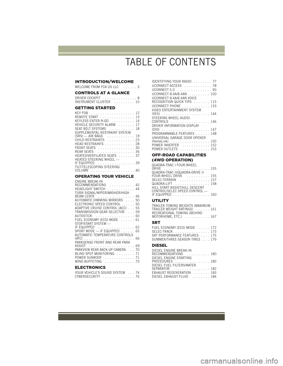
INTRODUCTION/WELCOME
WELCOME FROM FCA US LLC...... 3
CONTROLS AT A GLANCE
DRIVER COCKPIT............... 8
INSTRUMENT CLUSTER ......... 10
GETTING STARTED
KEYFOB ................... 12
REMOTE START............... 13
KEYLESS ENTER-N-GO .......... 14
VEHICLE SECURITY ALARM ....... 17
SEAT BELT SYSTEMS ........... 18
SUPPLEMENTAL RESTRAINT SYSTEM
(SRS) — AIR BAGS ............ 19
CHILD RESTRAINTS ............ 23
HEAD RESTRAINTS ............. 28
FRONT SEATS ................ 30
REAR SEATS ................ 36
HEATED/VENTILATED SEATS ....... 37
HEATED STEERING WHEEL —
IF EQUIPPED ................ 39
TILT/TELESCOPING STEERING
COLUMN ................... 40
OPERATING YOUR VEHICLE
ENGINE BREAK-IN
RECOMMENDATIONS ........... 42
HEADLIGHT SWITCH ............ 44
TURN SIGNAL/WIPER/WASHER/HIGH
BEAM LEVER ................ 46
AUTOMATIC DIMMING MIRRORS .... 50
ELECTRONIC SPEED CONTROL ..... 50
ADAPTIVE CRUISE CONTROL (ACC) . . . 53
TRANSMISSION GEAR SELECTOR . . . 59
AUTOSTICK ................. 60
FUEL ECONOMY (ECO) MODE ...... 61
STOP/START SYSTEM —
IF EQUIPPED ................ 62
SPORT MODE — IF EQUIPPED ...... 65
AUTOMATIC TEMPERATURE CONTROLS
(ATC) ...................... 66
PARKSENSE FRONT AND REAR PARK
ASSIST .................... 69
PARKVIEW REAR BACK-UP CAMERA.. 70
BLIND SPOT MONITORING ........ 71
POWER SUNROOF ............. 71
WIND BUFFETING ............. 73
ELECTRONICS
YOUR VEHICLE'S SOUND SYSTEM . . . 74
CYBERSECURITY.............. 76 IDENTIFYING YOUR RADIO
........ 77
UCONNECT ACCESS ............ 78
UCONNECT 5.0 ............... 90
UCONNECT 8.4A/8.4AN ......... 100
UCONNECT 8.4A/8.4AN VOICE
RECOGNITION QUICK TIPS ....... 115
UCONNECT PHONE ........... 133
VIDEO ENTERTAINMENT SYSTEM
(VES) ..................... 144
STEERING WHEEL AUDIO
CONTROLS ................. 146
DRIVER INFORMATION DISPLAY
(DID) ..................... 147
PROGRAMMABLE FEATURES ...... 148
UNIVERSAL GARAGE DOOR OPENER
(HomeLink) ................. 150
POWER INVERTER ............ 152
POWER OUTLETS ............. 153
OFF-ROAD CAPABILITIES
(4WD OPERATION)
QUADRA-TRAC I FOUR-WHEEL
DRIVE .................... 155
QUADRA-TRAC II/QUADRA-DRIVE II
FOUR-WHEEL DRIVE .......... 155
SELEC-TERRAIN ............. 157
QUADRA-LIFT ............... 158
HILL START ASSIST/HILL DESCENT
CONTROL/SELEC SPEED CONTROL —
IF EQUIPPED ................ 160
UTILITY
TRAILER TOWING WEIGHTS (MAXIMUM
TRAILER WEIGHT RATINGS) ...... 161
RECREATIONAL TOWING (BEHIND
MOTORHOME, ETC.) ........... 167
SRT
FUEL ECONOMY (ECO) MODE ..... 172
SELEC-TRACK ............... 173
SRT PERFORMANCE FEATURES .... 175
SUMMER/THREE-SEASON TIRES . . . 179
DIESEL
DIESEL ENGINE BREAK-IN
RECOMMENDATIONS .......... 180
DIESEL ENGINE STARTING
PROCEDURES ............... 180
DIESEL FUEL FILTERS/WATER
SEPARATOR ................ 182
EXHAUST REGENERATION ....... 183
DIESEL EXHAUST FLUID ........ 184
TABLE OF CONTENTS
Page 4 of 276
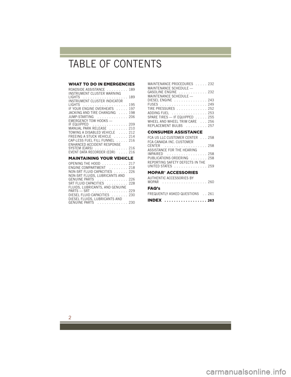
WHAT TO DO IN EMERGENCIES
ROADSIDE ASSISTANCE......... 189
INSTRUMENT CLUSTER WARNING
LIGHTS ................... 189
INSTRUMENT CLUSTER INDICATOR
LIGHTS ................... 195
IF YOUR ENGINE OVERHEATS ..... 197
JACKING AND TIRE CHANGING .... 198
JUMP-STARTING ............. 206
EMERGENCY TOW HOOKS —
IF EQUIPPED ............... 209
MANUAL PARK RELEASE ........ 210
TOWING A DISABLED VEHICLE .... 212
FREEING A STUCK VEHICLE ...... 214
CAP-LESS FUEL FILL FUNNEL ..... 216
ENHANCED ACCIDENT RESPONSE
SYSTEM (EARS) .............. 216
EVENT DATA RECORDER (EDR) .... 216
MAINTAINING YOUR VEHICLE
OPENING THE HOOD........... 217
ENGINE COMPARTMENT ........ 218
NON-SRT FLUID CAPACITIES ...... 226
NON-SRT FLUIDS, LUBRICANTS AND
GENUINE PARTS ............. 226
SRT FLUID CAPACITIES ......... 228
FLUIDS, LUBRICANTS, AND GENUINE
PARTS—SRT ............... 229
DIESEL FLUID CAPACITIES ....... 230
DIESEL FLUIDS, LUBRICANTS AND
GENUINE PARTS ............. 230 MAINTENANCE PROCEDURES
..... 232
MAINTENANCE SCHEDULE —
GASOLINE ENGINE ............ 232
MAINTENANCE SCHEDULE —
DIESEL ENGINE .............. 243
FUSES .................... 249
TIRE PRESSURES ............. 252
ADDING FUEL ............... 253
SPARE TIRES — IF EQUIPPED ..... 255
WHEEL AND WHEEL TRIM CARE . . . 256
REPLACEMENT BULBS ......... 257
CONSUMER ASSISTANCE
FCA US LLC CUSTOMER CENTER . . . 258
FCA CANADA INC. CUSTOMER
CENTER.................. 258
ASSISTANCE FOR THE HEARING
IMPAIRED ................. 258
PUBLICATIONS ORDERING ....... 258
REPORTING SAFETY DEFECTS IN THE
UNITEDSTATES .............. 259
MOPAR® ACCESSORIES
AUTHENTIC ACCESSORIES BY
MOPAR ................... 260
FAQ ’ s
FREQUENTLY ASKED QUESTIONS . . 261
INDEX.................. 263
TABLE OF CONTENTS
2
Page 10 of 276
DRIVER COCKPIT
1. Headlight Switch pg. 44
2. Turn Signal/Wiper/Washer/High Beams Lever (Behind Steering Wheel) pg. 46
3. AutoStick pg. 60
4. Driver Information Display (DID) Controls pg. 147
5. Instrument Cluster pg. 10
6. Speed Control pg. 50
7. Engine Start/Stop Button (Behind Steering Wheel) pg. 16
8. Audio System (Touchscreen Radio Shown) pg. 74
CONTROLS AT A GLANCE
8
Page 21 of 276
SUPPLEMENTAL RESTRAINT SYSTEM (SRS) — AIR
BAGS
Air Bag System Components
Your vehicle may be equipped with the following air bag system components:
• Occupant Restraint Controller (ORC)
• Air Bag Warning Light
• Steering Wheel and Column
• Instrument Panel
• Knee Impact Bolsters
• Advanced Front Air Bags
• Supplemental Knee Air Bags
• Supplemental Side Air Bags
• Front and Side Impact Sensors
• Seat Belt Pretensioners
• Seat Belt Buckle Switch
Advanced Front Air Bags
This vehicle has Advanced Front Air Bags for both the driver and front passenger as
a supplement to the seat belt restraint systems. The Advanced Front Air Bags will not
deploy in every type of collision.
Advanced Front Air Bags are designed to provide additional protection by supple-
menting the seat belts. Advanced Front Air Bags are not expected to reduce the risk
of injury in rear, side, or rollover collisions.
The Advanced Front Air Bags will not deploy in all frontal collisions, including some
that may produce substantial vehicle damage — for example, some pole collisions,
truck underrides, and angle offset collisions.
On the other hand, depending on the type and location of impact, Advanced Front Air
Bags may deploy in crashes with little vehicle front-end damage but that produce a
severe initial deceleration.
Because air bag sensors measure vehicle deceleration over time, vehicle speed and
damage by themselves are not good indicators of whether or not an air bag should
have deployed.
Seat belts are necessary for your protection in all collisions, and also are needed to
help keep you in position, away from an inflating air bag.
After any collision, the vehicle should be taken to an authorized dealer immediately.
Do not drive your vehicle after the air bags have deployed. If you are involved in
another collision, the air bags will not be in place to protect you.
GETTING STARTED
19
Page 22 of 276
If it is necessary to modify the air bag system for persons with disabilities, contact
your authorized dealer.
Refer to the Owner's Manual on the DVD for further details regarding the Supple-
mental Restraint System (SRS).
Supplemental Knee Air Bags
This vehicle is equipped with a Supplemental Driver Knee Air Bag mounted in the
instrument panel below the steering column. The Supplemental Driver Knee Air Bag
provides enhanced protection during a frontal impact by working together with the
seat belts, pretensioners, and Advanced Front Air Bags.
WARNING!
• Relying on the air bags alone could lead to more severe injuries in a collision.The air bags work with your seat belt to restrain you properly. In some
collisions, the air bags won't deploy at all. Always wear your seat belts even
though you have air bags.
• Being too close to the steering wheel or instrument panel during Advanced
Front Air Bag deployment could cause serious injury, including death. Air bags
need room to inflate. Sit back, comfortably extending your arms to reach the
steering wheel or instrument panel.
• No objects should be placed over or near the air bag on the instrument panel
or steering wheel because any such objects could cause harm if the vehicle is
in a collision severe enough to cause the air bag to inflate.
Supplemental Side Air Bags
This vehicle is equipped with Supplemental Seat-Mounted Side Air Bags (SABs)
located in the outboard side of the front seats. The SABs are marked with a SRS
AIRBAG or AIRBAG label sewn into the outboard side of the seats.
This vehicle is equipped with Supplemental Side Air Bag Inflatable Curtains
(SABICs) located above the side windows. The trim covering the SABICs is labeled
SRS AIRBAG or AIRBAG. The SABICs may help reduce the risk of partial or complete
ejection of vehicle occupants through side windows in certain rollover or side impact
events.
The SABICs and SABs (“Side Air Bags”) are designed to activate in certain side
impacts and certain rollover events. The Occupant Restraint Controller (“ORC”)
determines whether the deployment of the Side Air Bags in a particular side impact
or rollover event is appropriate, based on the severity and type of collision. Vehicle
damage by itself is not a good indicator of whether or not Side Air Bags should have
deployed.
GETTING STARTED
20
Page 41 of 276
Front Ventilated Seats
If your vehicle is equipped with ventilated seats, the seat cushion and seat back will
have fans that draw the air from the passenger compartment and move air through
fine perforations in the seat cover to help keep the driver and front passenger cooler
in higher ambient temperatures. The fans operate at two speeds, HI and LO.
The front ventilated seats control buttons are located within the Uconnect system.
You can gain access to the control buttons through the climate screen or the controls
screen.
• Press the ventilated seat button
once to choose HI.
• Press the ventilated seat button
a second time to choose LO.
• Press the ventilated seat button
a third time to turn the ventilated seat OFF.
NOTE:
The engine must be running for the ventilated seats to operate.
Vehicles Equipped With Remote Start
On models that are equipped with remote start, the ventilated seats can be
programmed to come on during a remote start.
This feature can be programmed through the Uconnect system. Refer to “Uconnect
Settings” in “Understanding Your Instrument Panel” in the Owner's Manual on the
DVD.
HEATED STEERING WHEEL — IF EQUIPPED
The steering wheel contains a heating element that helps warm your hands in cold
weather. The heated steering wheel has only one temperature setting. Once the
heated steering wheel has been turned on it will operate for up to 80 minutes before
automatically shutting off. The heated steering wheel can shut off early or may not
turn on when the steering wheel is already warm.
The heated steering wheel control button is located within the Uconnect system. You
can gain access to the control button through the climate screen or the controls
screen.
• Press the heated steering wheel button
once to turn the heating element ON.
• Press the heated steering wheel button
a second time to turn the heating
element OFF.
NOTE:
The engine must be running for the heated steering wheel to operate.
GETTING STARTED
39
Page 42 of 276
Vehicles Equipped With Remote Start
On models that are equipped with remote start, the heated steering wheel can be
programmed to come on during a remote start through the Uconnect system. Refer to
“Uconnect Settings” in “Understanding Your Instrument Panel” in the Owners
Manual on the DVD for further information.
WARNING!
• Persons who are unable to feel pain to the skin because of advanced age,chronic illness, diabetes, spinal cord injury, medication, alcohol use, exhaus-
tion, or other physical conditions must exercise care when using the steering
wheel heater. It may cause burns even at low temperatures, especially if used
for long periods.
• Do not place anything on the steering wheel that insulates against heat, such
as a blanket or steering wheel covers of any type and material. This may cause
the steering wheel heater to overheat.
TILT/TELESCOPING STEERING COLUMN
Manual Tilt/Telescoping Steering Column
This feature allows you to tilt the steering column upward or downward. It also allows
you to lengthen or shorten the steering column. The tilt/telescoping lever is located
below the steering wheel at the end of the steering column.
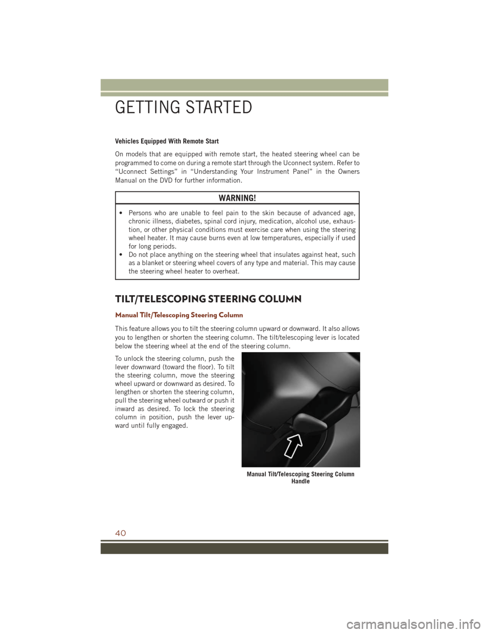
To unlock the steering column, push the
lever downward (toward the floor). To tilt
the steering column, move the steering
wheel upward or downward as desired. To
lengthen or shorten the steering column,
pull the steering wheel outward or push it
inward as desired. To lock the steering
column in position, push the lever up-
ward until fully engaged.
Manual Tilt/Telescoping Steering Column Handle
GETTING STARTED
40
Page 46 of 276
For the first 1500 miles (2414 km):
• Do not participate in track events, sport driving schools, or similar activities duringthe first 1500 miles (2414 km).
NOTE:
Check engine oil with every refueling and add if necessary. Oil and fuel consumption
may be higher through the first oil change interval.
HEADLIGHT SWITCH
The headlight switch is located on the left side of the instrument panel, next to the
steering wheel. The headlight switch controls the operation of the headlights, parking
lights, instrument panel lights, cargo lights and fog lights (if equipped).
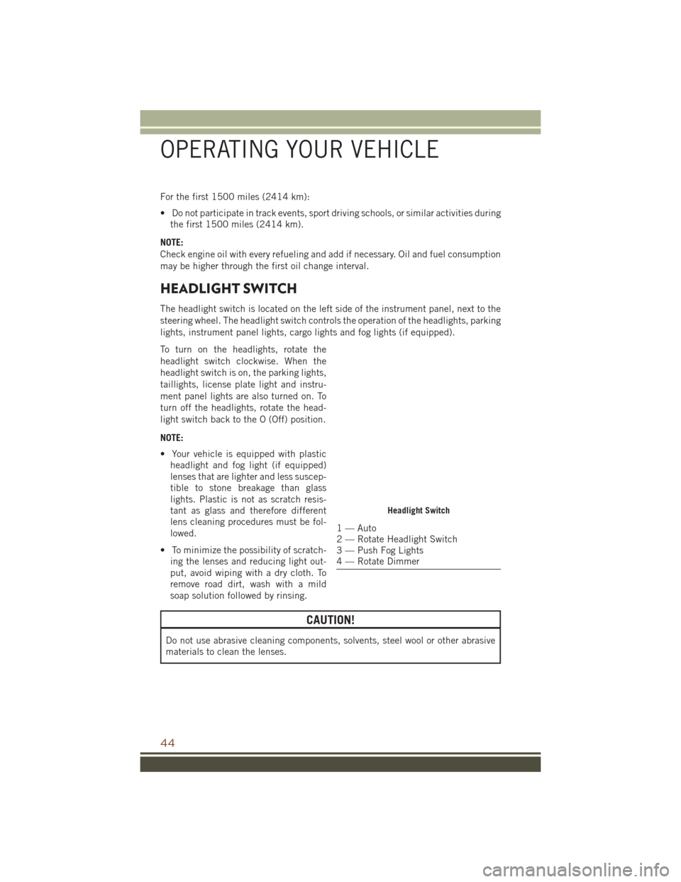
To turn on the headlights, rotate the
headlight switch clockwise. When the
headlight switch is on, the parking lights,
taillights, license plate light and instru-
ment panel lights are also turned on. To
turn off the headlights, rotate the head-
light switch back to the O (Off) position.
NOTE:
• Your vehicle is equipped with plastic headlight and fog light (if equipped)
lenses that are lighter and less suscep-
tible to stone breakage than glass
lights. Plastic is not as scratch resis-
tant as glass and therefore different
lens cleaning procedures must be fol-
lowed.
• To minimize the possibility of scratch- ing the lenses and reducing light out-
put, avoid wiping with a dry cloth. To
remove road dirt, wash with a mild
soap solution followed by rinsing.
CAUTION!
Do not use abrasive cleaning components, solvents, steel wool or other abrasive
materials to clean the lenses.
Headlight Switch
1 — Auto
2 — Rotate Headlight Switch
3 — Push Fog Lights
4 — Rotate Dimmer
OPERATING YOUR VEHICLE
44
Page 47 of 276
Automatic Headlights — If Equipped
This system automatically turns the headlights on or off according to ambient light
levels. To turn the system on, rotate the headlight switch to the A (AUTO) position.
When the system is on, the Headlight Delay feature is also on. This means the
headlights will stay on for up to 90 seconds after you turn the ignition switch to the
OFF position. To turn the automatic headlights off, turn the headlight switch out of
the AUTO position.
NOTE:
The engine must be running before the headlights will turn on in the Automatic
Mode.
Automatic High Beam — If Equipped
The Automatic High Beam Headlamp Control system provides increased forward
lighting at night by automating high beam control through the use of a digital camera
mounted on the inside rearview mirror. This camera detects vehicle specific light and
automatically switches from high beams to low beams until the approaching vehicle
is out of view.
NOTE:
• The Automatic High Beam Headlamp Control can be turned on or off using theUconnect System. Refer to “Uconnect Settings” in “Understanding Your Instru-
ment Panel” in the Owner’s Manual on the DVD for further information.
• Broken, muddy, or obstructed headlights and taillights of vehicles in the field of view will cause headlights to remain on longer (closer to the vehicle). Also, dirt,
film, and other obstructions on the windshield or camera lens will cause the
system to function improperly.
• To opt out of the Advanced Auto High-Beam Sensitivity Control (default) and enter Reduced High-Beam Sensitivity Control (not recommended), toggle highbeam
lever 6 full on/off cycles within 10 seconds of ignition ON. System will return to
default setting upon ignition off.
If the windshield or Automatic High Beam Headlamp Control mirror is replaced, the
mirror must be re-aimed to ensure proper performance. See your local authorized
dealer.
Interior Lights
Courtesy and dome lights are turned on when the front doors are opened or when the
dimmer control (rotating wheel on the right side of the headlight switch) is rotated to
its farthest upward position. If your vehicle is equipped with Remote Keyless Entry
(RKE) and the UNLOCK button is pressed on the RKE transmitter the courtesy and
dome lights will turn on. When a door is open and the interior lights are on, rotating
the dimmer control all the way down, to the OFF detent, will cause all the interior
lights to go out. This is also known as the “Party” mode because it allows the doors
to stay open for extended periods of time without discharging the vehicle’s battery.
OPERATING YOUR VEHICLE
45
Page 48 of 276
The brightness of the instrument panel lighting can be regulated by rotating the
dimmer control up (brighter) or down (dimmer). When the headlights are on you can
supplement the brightness of the odometer, trip odometer, radio and overhead
console by rotating the control to its farthest position up until you hear a click. This
feature is termed the “Parade” mode and is useful when headlights are required
during the day.
TURN SIGNAL/WIPER/WASHER/HIGH BEAM LEVER
The multifunction lever is located on the left side of the steering column.
Turn Signals
Move the multifunction lever up or down and the arrows on each side of the
instrument cluster flash to show proper operation of the front and rear turn signal
lights.
NOTE:
If either light remains on and does not flash, or there is a very fast flash rate, check
for a defective outside light bulb. If an indicator fails to light when the lever is moved,
it would suggest that the indicator bulb is defective.
Lane Change Assist
Tap the lever up or down once, without moving beyond the detent, and the turn signal
(right or left) will flash three times then automatically turn off.
High/Low Beam Switch
Push the multifunction lever toward the instrument panel to switch the headlights to
high beams. Pulling the multifunction back toward the steering wheel will turn the
low beams back on, or shut the high beams off.
Multifunction Lever
OPERATING YOUR VEHICLE
46