air condition JEEP GRAND CHEROKEE 2017 WK2 / 4.G Owner's Manual
[x] Cancel search | Manufacturer: JEEP, Model Year: 2017, Model line: GRAND CHEROKEE, Model: JEEP GRAND CHEROKEE 2017 WK2 / 4.GPages: 372
Page 113 of 372
for 10 minutes above 15 mph (24 km/h). The
TPMS will chime, the "TPM Telltale Light"
will flash on and off for 75 seconds and then
remain on. The instrument cluster will dis-
play the “SERVICE TPM SYSTEM” message
and then display dashes (--) in place of the
pressure values.
Beginning with the next ignition cycle, the
TPMS will no longer chime or display the
“SERVICE TPM SYSTEM” message in the
instrument cluster but dashes (--) will remain
in place of the pressure values.
To reactivate the TPMS, replace all four
wheel and tire assemblies (road tires) with
tires equipped with TPM sensors. Then, drive
the vehicle for up to 10 minutes above
15 mph (24 km/h). The TPMS will chime, the
"TPM Telltale Light" will flash on and off for
75 seconds and then turn off. The instrument
cluster will display the “SERVICE TPM SYS-
TEM” message and then display pressure
values in place of the dashes. On the next
ignition cycle the "SERVICE TPM SYSTEM"
message will no longer be displayed as long
as no system fault exists.General Information
The following regulatory statement applies to
all radio frequency (RF) devices equipped in
this vehicle:
This device complies with Part 15 of the FCC
Rules and with Industry Canada license-
exempt RSS standard(s). Operation is sub-
ject to the following two conditions:
(1) This device may not cause harmful inter-
ference, and
(2) This device must accept any interference
received, including interference that may
cause undesired operation.
NOTE:
Changes or modifications not expressly ap-
proved by the party responsible for compli-
ance could void the user’s authority to oper-
ate the equipment.
OCCUPANT RESTRAINT
SYSTEMS
Some of the most important safety features in
your vehicle are the restraint systems:
Occupant Restraint Systems Features
• Seat Belt Systems
• Supplemental Restraint Systems (SRS)Air Bags
• Supplemental Active Head Restraints
• Child Restraints
Some of the safety features described in this
section may be standard equipment on some
models, or may be optional equipment on
others. If you are not sure, ask your autho-
rized dealer.
Important Safety Precautions
Please pay close attention to the information
in this section. It tells you how to use your
restraint system properly, to keep you and
your passengers as safe as possible.
Here are some simple steps you can take to
minimize the risk of harm from a deploying
air bag:
1. Children 12 years old and under should always ride buckled up in a vehicle with a
rear seat.
111
Page 115 of 372
Initial Indication
If the driver is unbuckled when the ignition
switch is first in the START or ON/RUN posi-
tion, a chime will signal for a few seconds. If
the driver or outboard front seat passenger (if
equipped with outboard front passenger seat
BeltAlert) is unbuckled when the ignition
switch is first in the START or ON/RUN posi-
tion the Seat Belt Reminder Light will turn on
and remain on until both outboard front seat
belts are buckled. The outboard front passen-
ger seat BeltAlert is not active when an out-
board front passenger seat is unoccupied.
BeltAlert Warning Sequence
The BeltAlert warning sequence is activated
when the vehicle is moving above a specified
vehicle speed range and the driver or out-
board front seat passenger is unbuckled (if
equipped with outboard front passenger seat
BeltAlert) (the outboard front passenger seat
BeltAlert is not active when the outboard
front passenger seat is unoccupied). The
BeltAlert warning sequence starts by blinking
the Seat Belt Reminder Light and sounding
an intermittent chime. Once the BeltAlert
warning sequence has completed, the SeatBelt Reminder Light will remain on until the
seat belts are buckled. The BeltAlert warning
sequence may repeat based on vehicle speed
until the driver and occupied outboard front
seat passenger seat belts are buckled. The
driver should instruct all occupants to buckle
their seat belts.
Change Of Status
If the driver or outboard front seat passenger
(if equipped with outboard front passenger
seat BeltAlert) unbuckles their seat belt while
the vehicle is traveling, the BeltAlert warning
sequence will begin until the seat belts are
buckled again. The outboard front passenger
seat BeltAlert is not active when the outboard
front passenger seat is unoccupied. BeltAlert
may be triggered when an animal or other
items are placed on the outboard front pas-
senger seat or when the seat is folded flat (if
equipped). It is recommended that pets be
restrained in the rear seat (if equipped) in pet
harnesses or pet carriers that are secured by
seat belts, and cargo is properly stowed.
BeltAlert can be activated or deactivated by
your authorized dealer. FCA US LLC does not
recommend deactivating BeltAlert.NOTE:
If BeltAlert has been deactivated and the
driver or outboard front seat passenger (if
equipped with outboard front passenger seat
BeltAlert) is unbuckled the Seat Belt Re-
minder Light will turn on and remain on until
the driver and outboard front seat passenger
seat belts are buckled.
Lap/Shoulder Belts
All seating positions in your vehicle are
equipped with lap/shoulder belts.
The seat belt webbing retractor will lock only
during very sudden stops or collisions. This
feature allows the shoulder part of the seat
belt to move freely with you under normal
conditions. However, in a collision the seat
belt will lock and reduce your risk of striking
the inside of the vehicle or being thrown out
of the vehicle.
WARNING!
• Relying on the air bags alone could lead
to more severe injuries in a collision. The
air bags work with your seat belt to
113
Page 123 of 372
Supplemental Restraint System (SRS)
Some of the safety features described in this
section may be standard equipment on some
models, or may be optional equipment on
others. If you are not sure, ask your autho-
rized dealer.
The air bag system must be ready to protect
you in a collision. The Occupant Restraint
Controller (ORC) monitors the internal cir-
cuits and interconnecting wiring associated
with the electrical Air Bag System Compo-
nents. Your vehicle may be equipped with the
following Air Bag System Components:
Air Bag System Components
• Occupant Restraint Controller (ORC)
• Air Bag Warning Light
• Steering Wheel and Column
• Instrument Panel
• Knee Impact Bolsters
• Driver and Front Passenger Air Bags
• Supplemental Side Air Bags
• Supplemental Knee Air Bags
• Front and Side Impact Sensors• Seat Belt Pretensioners
• Seat Belt Buckle Switch
Air Bag Warning Light
The ORC monitors the readiness of the
electronic parts of the air bag system when-
ever the ignition switch is in the START or
ON/RUN position. If the ignition switch is in
the OFF position or in the ACC position, the
air bag system is not on and the air bags will
not inflate.
The ORC contains a backup power supply
system that may deploy the air bag system
even if the battery loses power or it becomes
disconnected prior to deployment.
The ORC turns on the Air Bag Warning Light
in the instrument panel for approximately
four to eight seconds for a self-check when
the ignition switch is first in the ON/RUN
position. After the self-check, the Air Bag
Warning Light will turn off. If the ORC detects
a malfunction in any part of the system, it
turns on the Air Bag Warning Light, either
momentarily or continuously. A single chime
will sound to alert you if the light comes on
again after initial startup. The ORC also includes diagnostics that will
illuminate the instrument panel Air Bag
Warning Light if a malfunction is detected
that could affect the air bag system. The
diagnostics also record the nature of the
malfunction. While the air bag system is
designed to be maintenance free, if any of the
following occurs, have an authorized dealer
service the air bag system immediately.
• The Air Bag Warning Light does not come
on during the four to eight seconds when
the ignition switch is first in the ON/RUN
position.
• The Air Bag Warning Light remains on after the four to eight-second interval.
• The Air Bag Warning Light comes on inter- mittently or remains on while driving.
NOTE:
If the speedometer, tachometer, or any en-
gine related gauges are not working, the Oc-
cupant Restraint Controller (ORC) may also
be disabled. In this condition the air bags
may not be ready to inflate for your protec-
tion. Have an authorized dealer service the air
bag system immediately.
121
Page 146 of 372
Front seat belt assemblies must be replaced
after a collision. Rear seat belt assemblies
must be replaced after a collision if they have
been damaged (i.e., bent retractor, torn web-
bing, etc.). If there is any question regarding
seat belt or retractor condition, replace the
seat belt.
Air Bag Warning Light
The Air Bag warning lightwill turn on for
four to eight seconds as a bulb check when
the ignition switch is first turned to ON/RUN.
If the light is either not on during starting,
stays on, or turns on while driving, have the
system inspected at an authorized dealer as
soon as possible. This light will illuminate
with a single chime when a fault with the Air
Bag Warning Light has been detected, it will
stay on until the fault is cleared. If the light
comes on intermittently or remains on while
driving, have an authorized dealer service the
vehicle immediately. Refer to “Occupant Re-
straint Systems” in “Safety” for further infor-
mation.
Defroster
Check operation by selecting the defrost
mode and place the blower control on high
speed. You should be able to feel the air
directed against the windshield. See your
authorized dealer for service if your defroster
is inoperable.
Floor Mat Safety Information
Always use floor mats designed to fit your
vehicle. Only use a floor mat that does not
interfere with the operation of the accelera-
tor, brake or clutch pedals. Only use a floor
mat that is securely attached using the floor
mat fasteners so it cannot slip out of position
and interfere with the accelerator, brake or
clutch pedals or impair safe operation of your
vehicle in other ways.
WARNING!
An improperly attached, damaged, folded,
or stacked floor mat, or damaged floor mat
fasteners may cause your floor mat to
interfere with the accelerator, brake, or
clutch pedals and cause a loss of vehicle
WARNING!
control. To prevent SERIOUS INJURY or
DEATH:
• ALWAYS securely attach
your floor
mat using the floor mat fasteners. DO
NOT install your floor mat upside down
or turn your floor mat over. Lightly pull to
confirm mat is secured using the floor
mat fasteners on a regular basis.
• ALWAYS REMOVE THE EXISTING
FLOOR MAT FROM THE VEHICLE
before installing any other floor mat.
NEVER install or stack an additional
floor mat on top of an existing floor mat.
• ONLY install floor mats designed to fit
your vehicle. NEVER install a floor mat
that cannot be properly attached and
secured to your vehicle. If a floor mat
needs to be replaced, only use a FCA
approved floor mat for the specific
make, model, and year of your vehicle.
• ONLY use the driver’s side floor mat on
the driver’s side floor area. To check for
interference, with the vehicle properly
parked with the engine off, fully depress
the accelerator, the brake, and the
SAFETY
144
Page 160 of 372
CAUTION!
Damage to the transmission may occur if
the following precautions are not ob-
served:
• Shift into or out of PARK or REVERSEonly after the vehicle has come to a
complete stop.
• Do not shift between PARK, REVERSE,
NEUTRAL, or DRIVE when the engine is
above idle speed.
• Before shifting into any gear, make sure
your foot is firmly pressing the brake
pedal.
NOTE:
You must press and hold the brake pedal
while shifting out of PARK.
Ignition Park Interlock
This vehicle is equipped with a Ignition Park
Interlock which requires the transmission to
be in PARK before the ignition can be turned
to the OFF mode. This helps the driver avoid
inadvertently leaving the vehicle without placing the transmission in PARK. This sys-
tem also locks the transmission in PARK
whenever the ignition is in the OFF mode.
Brake/Transmission Shift Interlock
System
This vehicle is equipped with a Brake Trans-
mission Shift Interlock system (BTSI) that
holds the transmission gear selector in PARK
unless the brakes are applied. To shift the
transmission out of PARK, the engine must
be running and the brake pedal must be
pressed. The brake pedal must also be
pressed to shift from NEUTRAL into DRIVE or
REVERSE when the vehicle is stopped or
moving at low speeds.
Fuel Economy (ECO) Mode
The Fuel Economy (ECO) mode can improve
the vehicle's overall fuel economy during nor-
mal driving conditions. Push the “ECO”
switch in the center stack of the instrument
panel to activate or disable ECO mode. An
amber light on the switch indicates when
ECO mode is disabled (for regular models) or
a blue light when enabled (for SRT models).
When the Fuel Economy (ECO) Mode is en-
gaged, the vehicle control systems will
change the following:
• The transmission will upshift sooner and
downshift later.
• The overall driving performance will be more conservative.
• Vehicles with Quadra-Lift air suspension will operate in "Aero" mode over a broader
speed range. Refer to the section on
Quadra-Lift for further information.
ECO SwitchSTARTING AND OPERATING
158
Page 166 of 372
NOTE:
• If shift conditions/interlocks are not met,or a transfer case motor temperature pro-
tection condition exists, a “For 4x4 High
Slow Below 3 mph (5 km/h) Put Trans in N
push 4 Low” message will flash from the
instrument cluster display. Refer to “In-
strument Cluster Display” in “Getting To
Know Your Instrument Panel” for further
information.
• Shifting into or out of 4WD LOW is pos- sible with the vehicle completely stopped;
however, difficulty may occur due to the
mating clutch teeth not being properly
aligned. Several attempts may be required
for clutch teeth alignment and shift
completion to occur. The preferred
method is with the vehicle rolling 0 to
3 mph (0 to 5 km/h). If the vehicle is
moving faster than 3 mph (5 km/h), the
transfer case will not allow the shift.Shifting Into NEUTRAL (N)
WARNING!
You or others could be injured or killed if
you leave the vehicle unattended with the
transfer case in the NEUTRAL (N) position
without first fully engaging the parking
brake. The NEUTRAL (N) position disen-
gages both the front and rear drive shafts
from the powertrain and will allow the
vehicle to roll, even if the transmission is
in PARK. The parking brake should always
be applied when the driver is not in the
vehicle.
1. Bring the vehicle to a complete stop, with the engine running.
2. Press and hold the brake pedal.
3. Shift the transmission into NEUTRAL.
4. If vehicle is equipped with Quadra-Lift air suspension, ensure the vehicle is set to
Normal Ride Height.
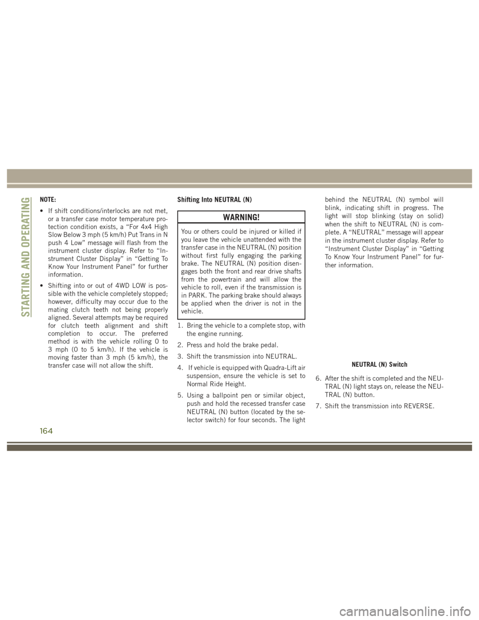
5. Using a ballpoint pen or similar object, push and hold the recessed transfer case
NEUTRAL (N) button (located by the se-
lector switch) for four seconds. The light behind the NEUTRAL (N) symbol will
blink, indicating shift in progress. The
light will stop blinking (stay on solid)
when the shift to NEUTRAL (N) is com-
plete. A “NEUTRAL” message will appear
in the instrument cluster display. Refer to
“Instrument Cluster Display” in “Getting
To Know Your Instrument Panel” for fur-
ther information.
6. After the shift is completed and the NEU- TRAL (N) light stays on, release the NEU-
TRAL (N) button.
7. Shift the transmission into REVERSE.
NEUTRAL (N) Switch
STARTING AND OPERATING
164
Page 168 of 372
QUADRA-LIFT — IF
EQUIPPED
Description
The Quadra-Lift air suspension system pro-
vides full time load leveling capability along
with the benefit of vehicle height adjustment
by the push of a button. The vehicle will
automatically raise and lower the ride height
to adapt to the appropriate driving condi-
tions. At higher speeds, the vehicle will lower
to an aerodynamic ride height and when
operating in off-road modes, the vehicle will
raise the ride height accordingly. The buttons
near the terrain switch in the center console
area can be used to set preferred ride height
to match the appropriate conditions.•Normal Ride Height (NRH) – This is the
standard position of the suspension and is
meant for normal driving. •
Off-Road 1 (OR1) (Raises the vehicle ap-
proximately 1.1 inches (28 mm) – This is
the primary position for all off-road driving
until OR2 is needed. A smoother and more
comfortable ride will result. Push the
“UP” button once from the NRH position
while the vehicle speed is below 38 mph
(61 km/h). When in the OR1 position, if
the vehicle speed remains between 40
mph (64 km/h) and 50 mph (80 km/h) for
greater than 20 seconds or if the vehicle
speed exceeds 50 mph (80 km/h), the
vehicle will be automatically lowered to
NRH. Refer to “Driving Tips” in “Starting
And Operating” for further information.
• Off-Road 2 (OR2) (Raises the vehicle ap-
proximately 2.2 inches (55 mm) – This po-
sition is intended for off-roading use only
where maximum ground clearance is re-
quired. To enter OR2, push the “UP” but-
ton twice from the NRH position or once
from the OR1 position while vehicle speed
is below 20 mph (32 km/h). While in OR2,
if the vehicle speed exceeds 25 mph
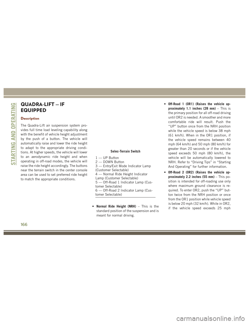
Selec-Terrain Switch
1 — UP Button
2 — DOWN Button
3 — Entry/Exit Mode Indicator Lamp
(Customer Selectable)
4 — Normal Ride Height Indicator
Lamp (Customer Selectable)
5 — Off-Road 1 Indicator Lamp (Cus-
tomer Selectable)
6 — Off-Road 2 Indicator Lamp (Cus-
tomer Selectable)
STARTING AND OPERATING
166
Page 170 of 372
After the engine is turned off, it may be
noticed that the air suspension system oper-
ates briefly, this is normal. The system is
correcting the position of the vehicle to en-
sure a proper appearance.
To assist with changing a spare tire, the
Quadra-Lift air suspension system has a fea-
ture which allows the automatic leveling to
be disabled. Refer to “Uconnect Settings” in
“Multimedia” for further information.
NOTE:
If equipped with a touch screen radio all
enabling/disabling of air suspension features
must be done through the radio. Refer to
“Uconnect Settings” in “Multimedia” for fur-
ther information.
WARNING!
The air suspension system uses a high
pressure volume of air to operate the sys-
tem. To avoid personal injury or damage to
the system, see your authorized dealer for
service.
Air Suspension Modes
The Air Suspension system has multiple
modes to protect the system in unique situa-
tions:
Tire/Jack Mode
To assist with changing a spare tire, the air
suspension system has a feature which al-
lows the automatic leveling to be disabled.
Refer to “Uconnect Settings” in “Multime-
dia” for further information.
NOTE:
This mode is intended to be enabled with
engine running.
Transport Mode
To assist with flat bed towing, the air suspen-
sion system has a feature which will put the
vehicle into Entry/Exit height and disable the
automatic load leveling system. Refer to
“Uconnect Settings” in “Multimedia” for fur-
ther information.
NOTE:
This mode is intended to be enabled with
engine running.Wheel Alignment Mode
Before performing a wheel alignment this
mode must be enabled. Refer to “Uconnect
Settings” in “Multimedia” for further infor-
mation.
NOTE:
This mode is intended to be enabled with
engine running.
If equipped with a touch screen radio all
enabling/disabling of air suspension features
must be done through the radio. Refer to
“Uconnect Settings” in “Multimedia” for fur-
ther information.
Instrument Cluster Display Messages
When the appropriate conditions exist, a
message will appear in the instrument clus-
ter. Refer to “Instrument Cluster Display” in
“Getting To Know Your Instrument Panel” for
further information.
Operation
The indicator lamps 3 through 6 will illumi-
nate to show the current position of the
vehicle. Flashing indicator lamps will show a
position which the system is working to
STARTING AND OPERATING
168
Page 172 of 372
SELEC-TERRAIN — IF
EQUIPPED
Selec-Terrain Mode Selection
Selec-Terrain combines the capabilities of
the vehicle control systems, along with driver
input, to provide the best performance for all
terrains. Selec-Terrain consists of the following posi-
tions:
•
Snow – Tuning set for additional stability
in inclement weather. Use on and off road
on loose traction surfaces such as snow.
When in Snow mode (depending on cer-
tain operating conditions), the transmis-
sion may use second gear (rather than first
gear) during launches, to minimize wheel
slippage. If equipped with air suspension,
the default ride height for Snow is Normal
Ride Height (NRH).
• Auto – Fully automatic full time four-wheel
drive operation can be used on and off
road. Balances traction with seamless
steering feel to provide improved handling
and acceleration over two-wheel drive ve-
hicles. If equipped with air suspension,
the level will change to Normal Ride
Height (NRH).
• Sand – Off road calibration for use on low
traction surfaces such as sand or wet
grass. Driveline is maximized for traction.
Some binding may be felt on less forgiving
surfaces. The electronic brake controls are
set to limit traction control management of throttle and wheel spin. If equipped
with air suspension, the default ride
height for Sand is Normal Ride Height
(NRH).
• Mud – Off road calibration for use on low
traction surfaces such as mud. Driveline is
maximized for traction. Some binding may
be felt on less forgiving surfaces. The
electronic brake controls are set to limit
traction control management of throttle
and wheel spin. If equipped with air sus-
pension, the level will change to Off Road
1.
• Rock – Off road calibration only available
in 4WD Low range. The vehicle is raised (if
equipped with Air Suspension) for im-
proved ground clearance. Traction based
tuning with improved steer-ability for use
on high traction off-road surfaces. Use for
low speed obstacles such as large rocks,
deep ruts, etc. If equipped with air sus-
pension, the vehicle level will change to
Off-Road 2. If the Selec-Terrain switch is
in ROCK mode, and the transfer case is
switched from 4WD Low to 4WD High, the
Selec-Terrain system will return to AUTO.
Selec-Terrain Switch
STARTING AND OPERATING
170
Page 214 of 372
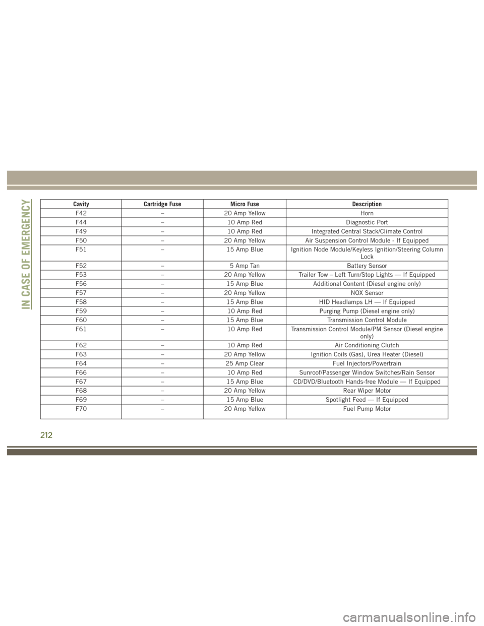
CavityCartridge Fuse Micro Fuse Description
F42 –20 Amp Yellow Horn
F44 –10 Amp Red Diagnostic Port
F49 –10 Amp Red Integrated Central Stack/Climate Control
F50 –20 Amp Yellow Air Suspension Control Module - If Equipped
F51 –15 Amp Blue Ignition Node Module/Keyless Ignition/Steering Column
Lock
F52 –5 Amp Tan Battery Sensor
F53 –20 Amp Yellow Trailer Tow – Left Turn/Stop Lights — If Equipped
F56 –15 Amp Blue Additional Content (Diesel engine only)
F57 –20 Amp Yellow NOX Sensor
F58 –15 Amp Blue HID Headlamps LH — If Equipped
F59 –10 Amp Red Purging Pump (Diesel engine only)
F60 –15 Amp Blue Transmission Control Module
F61 –10 Amp Red Transmission Control Module/PM Sensor (Diesel engine
only)
F62 –10 Amp Red Air Conditioning Clutch
F63 –20 Amp Yellow Ignition Coils (Gas), Urea Heater (Diesel)
F64 –25 Amp Clear Fuel Injectors/Powertrain
F66 –10 Amp Red Sunroof/Passenger Window Switches/Rain Sensor
F67 –15 Amp Blue CD/DVD/Bluetooth Hands-free Module — If Equipped
F68 –20 Amp Yellow Rear Wiper Motor
F69 –15 Amp Blue Spotlight Feed — If Equipped
F70 –20 Amp Yellow Fuel Pump Motor
IN CASE OF EMERGENCY
212