brake light JEEP GRAND CHEROKEE 2017 WK2 / 4.G Owner's Manual
[x] Cancel search | Manufacturer: JEEP, Model Year: 2017, Model line: GRAND CHEROKEE, Model: JEEP GRAND CHEROKEE 2017 WK2 / 4.GPages: 372
Page 101 of 372
occurring during severe or evasive driving
maneuvers; it cannot prevent wheel lift due to
other factors, such as road conditions, leav-
ing the roadway, or striking objects or other
vehicles.
NOTE:
ERM is disabled anytime the ESC is in “Full
Off” mode (if equipped). Refer to “Electronic
Stability Control (ESC)” in this section for a
complete explanation of the available ESC
modes.
WARNING!
Many factors, such as vehicle loading,
road conditions and driving conditions,
influence the chance that wheel lift or
rollover may occur. ERM cannot prevent all
wheel lift or roll overs, especially those
that involve leaving the roadway or striking
objects or other vehicles. The capabilities
of an ERM-equipped vehicle must never
be exploited in a reckless or dangerous
manner which could jeopardize the user's
safety or the safety of others.
Trailer Sway Control (TSC)
TSC uses sensors in the vehicle to recognize
an excessively swaying trailer and will take
the appropriate actions to attempt to stop the
sway. TSC will become active automatically
once an excessively swaying trailer is recog-
nized. Note that TSC cannot stop all trailers
from swaying. Always use caution when tow-
ing a trailer and follow the trailer tongue
weight recommendations. Refer to “Trailer
Towing” in “Starting And Operating” for fur-
ther information. When TSC is functioning,
the “ESC Activation/Malfunction Indicator
Light” will flash, the engine power may be
reduced and you may feel the brakes being
applied to individual wheels to attempt to
stop the trailer from swaying. TSC is disabled
when the ESC system is in the “Partial Off” or
“Full Off” modes.
WARNING!
If TSC activates while driving, slow the
vehicle down, stop at the nearest safe
location, and adjust the trailer load to
eliminate trailer sway.
Ready Alert Braking (RAB)
Ready Alert Braking may reduce the time
required to reach full braking during emer-
gency braking situations. It anticipates when
an emergency braking situation may occur by
monitoring how fast the throttle is released by
the driver. The EBC will prepare the brake
system for a panic stop.
Rain Brake Support (RBS)
Rain Brake Support may improve braking
performance in wet conditions. It will periodi-
cally apply a small amount of brake pressure
to remove any water buildup on the front
brake rotors. It functions when the wind-
shield wipers are in LO or HI speed. When
Rain Brake Support is active, there is no
notification to the driver and no driver inter-
action is required.
Dynamic Steering Torque (DST)
Dynamic Steering Torque is a feature of the
ESC and EPS modules that provides torque at
the steering wheel for certain driving condi-
tions in which the ESC module is detecting
vehicle instability. The torque that the steer-
ing wheel receives is only meant to help the
99
Page 107 of 372

system will respond with both visual and
audible alerts when a detected object is pres-
ent. Whenever an audible alert is requested,
the radio is muted.
Blind Spot Alert Lights/Chime
When operating in Blind Spot Alert Lights/
Chime mode, the BSM system will provide a
visual alert in the appropriate side view mirror
based on a detected object. If the turn signal
is then activated, and it corresponds to an
alert present on that side of the vehicle, an
audible chime will also be sounded. When-
ever a turn signal and detected object are
present on the same side at the same time,
both the visual and audible alerts will be
issued. In addition to the audible alert the
radio (if on) will also be muted.
NOTE:
Whenever an audible alert is requested by the
BSM system, the radio is also muted.
When the system is in RCP, the system shall
respond with both visual and audible alerts
when a detected object is present. Wheneveran audible alert is requested, the radio is also
muted. Turn/hazard signal status is ignored;
the RCP state always requests the chime.
Blind Spot Alert Off
When the BSM system is turned off there will
be no visual or audible alerts from either the
BSM or RCP systems.
NOTE:
The BSM system will store the current oper-
ating mode when the vehicle is shut off. Each
time the vehicle is started the previously
stored mode will be recalled and used.
Forward Collision Warning (FCW)
The Forward Collision Warning (FCW) system
provides the driver with audible and visual
warnings within the instrument cluster dis-
play to warn the driver when it detects a
potential frontal collision. The warnings are
intended to provide the driver with enough
time to react, avoid or mitigate the potential
collision.
NOTE:
FCW monitors the information from the for-
ward looking sensors as well as the Electronic
Brake Controller (EBC), to calculate the prob-
ability of a forward collision. When the sys-
tem determines that a forward collision is
probable, the driver will be provided with
audible and visual warnings.
Turning FCW ON Or OFF
The forward collision button is located in the
Uconnect display in the controls settings.
• To turn the FCW system OFF, press the
forward collision button once to turn the
system OFF.
• To turn the FCW system back ON, press the forward collision button again to turn
the system ON.
NOTE:
• The default status of FCW is “On”, this allows the system to warn you of a possible
collision with the vehicle in front of you.
105
Page 146 of 372
Front seat belt assemblies must be replaced
after a collision. Rear seat belt assemblies
must be replaced after a collision if they have
been damaged (i.e., bent retractor, torn web-
bing, etc.). If there is any question regarding
seat belt or retractor condition, replace the
seat belt.
Air Bag Warning Light
The Air Bag warning lightwill turn on for
four to eight seconds as a bulb check when
the ignition switch is first turned to ON/RUN.
If the light is either not on during starting,
stays on, or turns on while driving, have the
system inspected at an authorized dealer as
soon as possible. This light will illuminate
with a single chime when a fault with the Air
Bag Warning Light has been detected, it will
stay on until the fault is cleared. If the light
comes on intermittently or remains on while
driving, have an authorized dealer service the
vehicle immediately. Refer to “Occupant Re-
straint Systems” in “Safety” for further infor-
mation.
Defroster
Check operation by selecting the defrost
mode and place the blower control on high
speed. You should be able to feel the air
directed against the windshield. See your
authorized dealer for service if your defroster
is inoperable.
Floor Mat Safety Information
Always use floor mats designed to fit your
vehicle. Only use a floor mat that does not
interfere with the operation of the accelera-
tor, brake or clutch pedals. Only use a floor
mat that is securely attached using the floor
mat fasteners so it cannot slip out of position
and interfere with the accelerator, brake or
clutch pedals or impair safe operation of your
vehicle in other ways.
WARNING!
An improperly attached, damaged, folded,
or stacked floor mat, or damaged floor mat
fasteners may cause your floor mat to
interfere with the accelerator, brake, or
clutch pedals and cause a loss of vehicle
WARNING!
control. To prevent SERIOUS INJURY or
DEATH:
• ALWAYS securely attach
your floor
mat using the floor mat fasteners. DO
NOT install your floor mat upside down
or turn your floor mat over. Lightly pull to
confirm mat is secured using the floor
mat fasteners on a regular basis.
• ALWAYS REMOVE THE EXISTING
FLOOR MAT FROM THE VEHICLE
before installing any other floor mat.
NEVER install or stack an additional
floor mat on top of an existing floor mat.
• ONLY install floor mats designed to fit
your vehicle. NEVER install a floor mat
that cannot be properly attached and
secured to your vehicle. If a floor mat
needs to be replaced, only use a FCA
approved floor mat for the specific
make, model, and year of your vehicle.
• ONLY use the driver’s side floor mat on
the driver’s side floor area. To check for
interference, with the vehicle properly
parked with the engine off, fully depress
the accelerator, the brake, and the
SAFETY
144
Page 147 of 372
WARNING!
clutch pedal (if present) to check for
interference. If your floor mat interferes
with the operation of any pedal, or is not
secure to the floor, remove the floor mat
from the vehicle and place the floor mat
in your trunk.
• ONLY use the passenger’s side floor mat
on the passenger’s side floor area.
• ALWAYS make sure objects cannot fall
or slide into the driver’s side floor area
when the vehicle is moving. Objects can
become trapped under accelerator,
brake, or clutch pedals and could cause
a loss of vehicle control.
• NEVER place any objects under the floor
mat (e.g., towels, keys, etc.). These ob-
jects could change the position of the
floor mat and may cause interference
with the accelerator, brake, or clutch
pedals.
• If the vehicle carpet has been removed
and re-installed, always properly attach
WARNING!
carpet to the floor and check the floor
mat fasteners are secure to the vehicle
carpet. Fully depress each pedal to
check for interference with the accelera-
tor, brake, or clutch pedals then re-
install the floor mats.
• It is recommended to only use mild soap
and water to clean your floor mats. After
cleaning, always check your floor mat
has been properly installed and is se-
cured to your vehicle using the floor mat
fasteners by lightly pulling mat.
Periodic Safety Checks You Should Make
Outside The Vehicle
Tires
Examine tires for excessive tread wear and
uneven wear patterns. Check for stones,
nails, glass, or other objects lodged in the
tread or sidewall. Inspect the tread for cuts and cracks. Inspect sidewalls for cuts,
cracks, and bulges. Check the wheel nuts for
tightness. Check the tires (including spare)
for proper cold inflation pressure.
Lights
Have someone observe the operation of brake
lights and exterior lights while you work the
controls. Check turn signal and high beam
indicator lights on the instrument panel.
Door Latches
Check for proper closing, latching, and lock-
ing.
Fluid Leaks
Check area under vehicle after overnight
parking for fuel, engine coolant, oil, or other
fluid leaks. Also, if gasoline fumes are de-
tected or if fuel, power steering fluid (if
equipped), or brake fluid leaks are sus-
pected. The cause should be located and
corrected immediately.
145
Page 153 of 372
The starter is allowed to crank for up to
30-second intervals. Waiting a few minutes
between such intervals will protect the starter
from overheating.
WARNING!
• Before exiting a vehicle, always shift theautomatic transmission into PARK and
apply the parking brake. Always make
sure the keyless ignition node is in the
“OFF” mode, remove the key fob from
the vehicle and lock the vehicle.
• Never leave children alone in a vehicle,
or with access to an unlocked vehicle.
Leaving children in a vehicle unattended
is dangerous for a number of reasons. A
child or others could be seriously or
fatally injured. Children should be
warned not to touch the parking brake,
brake pedal or the gear selector.
• Do not leave the key fob in or near the
vehicle, or in a location accessible to
children, and do not leave the ignition of
a vehicle equipped with Keyless Enter-
N-Go in the ACC or ON/RUN mode. A
WARNING!
child could operate power windows,
other controls, or move the vehicle.
• Do not leave children or animals inside
parked vehicles in hot weather. Interior
heat build-up may cause serious injury
or death.
NOTE:
Engine start up in very low ambient tempera-
ture could result in evident white smoke. This
condition will disappear as the engine warms
up.
CAUTION!
• The engine is allowed to crank as long as 30 seconds. If the engine fails to start
during this period, please wait at least
two minutes for the starter to cool before
repeating start procedure.
• If the “Water in Fuel Indicator Light”
remains on, DO NOT START engine be-
fore you drain the water from the fuel
filters to avoid engine damage. Refer to
“Draining Fuel/Water Separator Filter”
CAUTION!
in “Servicing And Maintenance” for fur-
ther information.
Automatic Transmission
Start the engine with the transmission gear
selector in the PARK position. Apply the
brake before shifting to any driving range.
Extreme Cold Weather
The engine block heater is a resistance heater
installed in the water jacket of the engine. It
requires a 110–115 Volt AC electrical outlet
with a grounded, three-wire extension cord.
Its use is recommended for environments
that routinely fall below -10°F (-23°C). It
should be used when the vehicle has not been
running overnight or longer periods and
should be plugged in two hours prior to start.
Its use is required for cold starts with tem-
peratures under -20°F (-28°C).
151
Page 154 of 372
NOTE:
The engine block heater cord is a factory
installed option. If your vehicle is not
equipped, heater cords are available from
your authorized MOPAR dealer.
• A 12 Volt heater built into the fuel filterhousing aids in preventing fuel gelling. It is
controlled by a built-in thermostat.
• A Diesel Pre-Heat system both improves engine starting and reduces the amount of
white smoke generated by a warming
engine.
Normal Starting Procedure — Keyless
Enter-N-Go
Observe the instrument panel cluster lights
when starting the engine.
NOTE:
Normal starting of either a cold or a warm
engine is obtained without pumping or press-
ing the accelerator pedal
1. Always apply the parking brake.
2. Press and hold the brake pedal while pushing the ENGINE START/STOP button
once. NOTE:
A delay of the start of up to five seconds is
possible under very cold conditions. The
"Wait to Start" telltale will be illuminated
during the pre-heat process, When the
engine Wait To Start light goes off the
engine will automatically crank.
CAUTION!
If the “Water in Fuel Indicator Light” re-
mains on, DO NOT START the engine be-
fore you drain the water from the fuel
filters to avoid engine damage. Refer to
“Draining Fuel/Water Separator Filter” in
“Servicing And Maintenance” for further
information.
3. The system will automatically engage the starter to crank the engine. If the vehicle
fails to start, the starter will disengage
automatically after 25 seconds.
4. If you wish to stop the cranking of the engine prior to the engine starting, push
the button again.
5. Check that the oil pressure warning light has turned off. 6. Release the parking brake.
Starting Fluids
The engine is equipped with a glow plug
preheating system. If the instructions in this
manual are followed, the engine should start
in all conditions and no type of starting fluid
should be used.
WARNING!
• Do not leave children or animals inside
parked vehicles in hot weather. Interior
heat build up may cause serious injury
or death.
• When leaving the vehicle, always make
sure the keyless ignition node is in the
“OFF” mode, remove the key fob from
the vehicle and lock the vehicle.
• Never leave children alone in a vehicle,
or with access to an unlocked vehicle.
Allowing children to be in a vehicle un-
attended is dangerous for a number of
reasons. A child or others could be seri-
ously or fatally injured. Children should
be warned not to touch the parking
brake, brake pedal or the gear selector.
STARTING AND OPERATING
152
Page 156 of 372
• Cabin heating or cooling is in process andan acceptable cabin temperature has not
been achieved.
• HVAC is set to full defrost mode at a high blower speed.
• HVAC set to MAX A/C.
• Engine has not reached normal operating temperature.
• The transmission is not in a forward gear.
• Hood is open.
• Vehicle is in 4LO transfer case mode.
• Brake pedal is not pressed with sufficient pressure.
Other Factors Which Can Inhibit Autostop In-
clude:
• Accelerator pedal input.
• Engine temp too high.
• 5 MPH threshold not achieved from previ- ous AUTOSTOP.
• Steering angle beyond threshold.
• ACC is on and speed is set. It may be possible for the vehicle to be driven
several times without the STOP/START sys-
tem going into a STOP/START READY state
under more extreme conditions of the items
listed above.
To Start The Engine While In Autostop
Mode
While in a forward gear, the engine will start
when the brake pedal is released or the
throttle pedal is depressed. The transmission
will automatically re-engage upon engine re-
start.
Conditions That Will Cause The Engine To Start
Automatically While In Autostop Mode:
• The transmission selector is moved out of
DRIVE.
• To maintain cabin temperature comfort.
• HVAC is set to full defrost mode.
• HVAC system temperature or fan speed is manually adjusted.
• Battery voltage drops too low.
• Low brake vacuum (e.g. after several brake pedal applications).
• STOP/START OFF switch is pushed. • A STOP/START system error occurs.
• 4WD system is put into 4LO mode.
To Manually Turn Off The Stop/Start
System
1. Push the STOP/START OFF switch (lo-
cated on the switch bank). The light on
the switch will illuminate.
2. The “STOP/START OFF” message will ap- pear in the instrument cluster display.
STOP/START Off Switch
STARTING AND OPERATING
154
Page 160 of 372
CAUTION!
Damage to the transmission may occur if
the following precautions are not ob-
served:
• Shift into or out of PARK or REVERSEonly after the vehicle has come to a
complete stop.
• Do not shift between PARK, REVERSE,
NEUTRAL, or DRIVE when the engine is
above idle speed.
• Before shifting into any gear, make sure
your foot is firmly pressing the brake
pedal.
NOTE:
You must press and hold the brake pedal
while shifting out of PARK.
Ignition Park Interlock
This vehicle is equipped with a Ignition Park
Interlock which requires the transmission to
be in PARK before the ignition can be turned
to the OFF mode. This helps the driver avoid
inadvertently leaving the vehicle without placing the transmission in PARK. This sys-
tem also locks the transmission in PARK
whenever the ignition is in the OFF mode.
Brake/Transmission Shift Interlock
System
This vehicle is equipped with a Brake Trans-
mission Shift Interlock system (BTSI) that
holds the transmission gear selector in PARK
unless the brakes are applied. To shift the
transmission out of PARK, the engine must
be running and the brake pedal must be
pressed. The brake pedal must also be
pressed to shift from NEUTRAL into DRIVE or
REVERSE when the vehicle is stopped or
moving at low speeds.
Fuel Economy (ECO) Mode
The Fuel Economy (ECO) mode can improve
the vehicle's overall fuel economy during nor-
mal driving conditions. Push the “ECO”
switch in the center stack of the instrument
panel to activate or disable ECO mode. An
amber light on the switch indicates when
ECO mode is disabled (for regular models) or
a blue light when enabled (for SRT models).
When the Fuel Economy (ECO) Mode is en-
gaged, the vehicle control systems will
change the following:
• The transmission will upshift sooner and
downshift later.
• The overall driving performance will be more conservative.
• Vehicles with Quadra-Lift air suspension will operate in "Aero" mode over a broader
speed range. Refer to the section on
Quadra-Lift for further information.
ECO SwitchSTARTING AND OPERATING
158
Page 165 of 372
WARNING!
You or others could be injured or killed if
you leave the vehicle unattended with the
power transfer unit in the NEUTRAL (N)
position without first fully engaging the
parking brake. The NEUTRAL (N) position
disengages both the front and rear drive-
shafts from the powertrain and will allow
the vehicle to roll, even if the transmission
is in PARK. The parking brake should al-
ways be applied when the driver is not in
the vehicle.
4WD LOW
This range is for low speed four-wheel drive. It
provides an additional gear reduction which
allows for increased torque to be delivered to
both the front and rear wheels while providing
maximum pulling power for loose, slippery
road surfaces only. Do not exceed 25 mph
(40 km/h).
NOTE:
Refer to “Selec-Terrain – If Equipped” for
further information on the various positions
and their intended usages.
Shifting Procedures
4WD HI To 4WD LOW
With the vehicle at speeds of 0 to 3 mph (0 to
5 km/h), the ignition switch in the ON posi-
tion or the engine running, shift the transmis-
sion into “N”, and push the “4WD LOW”
button once on the transfer case switch. The
“4WD LOW” indicator light in the instrument
cluster will begin to flash and remain on solid
when the shift is complete.NOTE:
If shift conditions/interlocks are not met, or a
transfer case motor temperature protection
condition exists, a “For 4x4 Low Slow Below
3 mph (5 km/h) Put Trans in “N” Press
4 Low” message will flash from the instru-
ment cluster display. Refer to “Instrument
Cluster Display” in “Getting To Know Your
Instrument Panel” for further information.
4WD LOW To 4WD HI
With the vehicle at speeds of 0 to 3 mph (0 to
5 km/h), the ignition switch in the ON posi-
tion or the engine running, shift the transmis-
sion into NEUTRAL, and push the “4WD
LOW” button once on the transfer case
switch. The “4WD LOW” indicator light in the
instrument cluster will flash and go out when
the shift is complete.
Transfer Case Switch
163
Page 166 of 372
NOTE:
• If shift conditions/interlocks are not met,or a transfer case motor temperature pro-
tection condition exists, a “For 4x4 High
Slow Below 3 mph (5 km/h) Put Trans in N
push 4 Low” message will flash from the
instrument cluster display. Refer to “In-
strument Cluster Display” in “Getting To
Know Your Instrument Panel” for further
information.
• Shifting into or out of 4WD LOW is pos- sible with the vehicle completely stopped;
however, difficulty may occur due to the
mating clutch teeth not being properly
aligned. Several attempts may be required
for clutch teeth alignment and shift
completion to occur. The preferred
method is with the vehicle rolling 0 to
3 mph (0 to 5 km/h). If the vehicle is
moving faster than 3 mph (5 km/h), the
transfer case will not allow the shift.Shifting Into NEUTRAL (N)
WARNING!
You or others could be injured or killed if
you leave the vehicle unattended with the
transfer case in the NEUTRAL (N) position
without first fully engaging the parking
brake. The NEUTRAL (N) position disen-
gages both the front and rear drive shafts
from the powertrain and will allow the
vehicle to roll, even if the transmission is
in PARK. The parking brake should always
be applied when the driver is not in the
vehicle.
1. Bring the vehicle to a complete stop, with the engine running.
2. Press and hold the brake pedal.
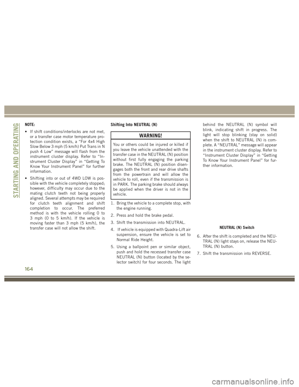
3. Shift the transmission into NEUTRAL.
4. If vehicle is equipped with Quadra-Lift air suspension, ensure the vehicle is set to
Normal Ride Height.
5. Using a ballpoint pen or similar object, push and hold the recessed transfer case
NEUTRAL (N) button (located by the se-
lector switch) for four seconds. The light behind the NEUTRAL (N) symbol will
blink, indicating shift in progress. The
light will stop blinking (stay on solid)
when the shift to NEUTRAL (N) is com-
plete. A “NEUTRAL” message will appear
in the instrument cluster display. Refer to
“Instrument Cluster Display” in “Getting
To Know Your Instrument Panel” for fur-
ther information.
6. After the shift is completed and the NEU- TRAL (N) light stays on, release the NEU-
TRAL (N) button.
7. Shift the transmission into REVERSE.
NEUTRAL (N) Switch
STARTING AND OPERATING
164