lock JEEP GRAND CHEROKEE 2017 WK2 / 4.G Owner's Manual
[x] Cancel search | Manufacturer: JEEP, Model Year: 2017, Model line: GRAND CHEROKEE, Model: JEEP GRAND CHEROKEE 2017 WK2 / 4.GPages: 372
Page 23 of 372
NOTE:
If “Unlock All Doors 1st Press” is pro-
grammed all doors will unlock when you grab
hold of the front driver’s door handle. To
select between “Unlock Driver Door 1st
Push” and “Unlock All Doors 1st Press,”
refer to “Uconnect Settings” in “Multime-
dia” for further information.
To Unlock From The Passenger Side
With a valid Passive Entry key fob within 5 ft
(1.5 m) of the passenger door handle, grab
the front passenger door handle to unlock all
four doors and the liftgate automatically.
NOTE:
All doors will unlock when the front passen-
ger door handle is grabbed regardless of the
driver’s door unlock preference setting (“Un-
lock Driver Door 1st Press” or “Unlock All
Doors 1st Press”).Preventing Inadvertent Locking Of Passive Entry
Key Fob In Vehicle (FOBIK-Safe)
To minimize the possibility of unintentionally
locking a Passive Entry key fob inside your
vehicle, the Passive Entry system is equipped
with an automatic door unlock feature which
will function if the ignition switch is in the
OFF position.
FOBIK-Safe only executes in vehicles with
passive entry. There are three situations that
trigger a FOBIK-Safe search in any passive
entry vehicle:
• A lock request is made by a valid Passive
Entry key fob while a door is open.
• A lock request is made by the Passive Entry door handle while a door is open.
• A lock request is made by the door panel switch while the door is open.
When any of these situations occur, after all
open doors are shut, the FOBIK-Safe search
will be executed. If it finds a Passive Entry
key fob inside the car, the car will unlock and
alert the customer. NOTE:
The vehicle will only unlock the doors when a
valid Passive Entry key fob is detected inside
the vehicle. The vehicle will not unlock the
doors when any of the following conditions
are true:
• The doors are manually locked using the
door lock knobs.
• Three attempts are made to lock the doors using the door panel switch and then close
the doors.
• There is a valid Passive Entry key fob outside the vehicle within 5 ft. (1.5 m) of
a Passive Entry door handle.
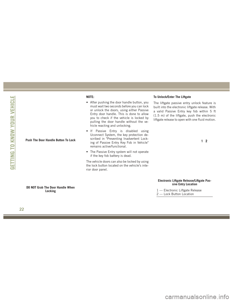
To Lock The Vehicle’s Doors And Liftgate
With one of the vehicle’s Passive Entry key
fob within 5 ft (1.5 m) of the driver or
passenger front door handles, pushing the
passive entry lock button will lock the ve-
hicle.
DO NOT grab the door handle, when pushing
the door handle lock button. This could un-
lock the door(s).
21
Page 24 of 372
NOTE:
• After pushing the door handle button, youmust wait two seconds before you can lock
or unlock the doors, using either Passive
Entry door handle. This is done to allow
you to check if the vehicle is locked by
pulling the door handle without the ve-
hicle reacting and unlocking.
• If Passive Entry is disabled using Uconnect System, the key protection de-
scribed in "Preventing Inadvertent Lock-
ing of Passive Entry Key Fob in Vehicle"
remains active/functional.
• The Passive Entry system will not operate if the key fob battery is dead.
The vehicle doors can also be locked by using
the lock button located on the vehicle’s inte-
rior door panel. To Unlock/Enter The Liftgate
The liftgate passive entry unlock feature is
built into the electronic liftgate release. With
a valid Passive Entry key fob within 5 ft
(1.5 m) of the liftgate, push the electronic
liftgate release to open with one fluid motion.
Push The Door Handle Button To Lock
DO NOT Grab The Door Handle When
Locking
Electronic Liftgate Release/Liftgate Pas-sive Entry Location
1 — Electronic Liftgate Release
2 — Lock Button Location
GETTING TO KNOW YOUR VEHICLE
22
Page 25 of 372
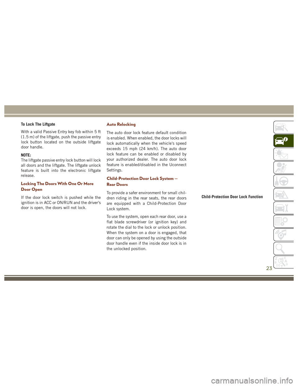
To Lock The Liftgate
With a valid Passive Entry key fob within 5 ft
(1.5 m) of the liftgate, push the passive entry
lock button located on the outside liftgate
door handle.
NOTE:
The liftgate passive entry lock button will lock
all doors and the liftgate. The liftgate unlock
feature is built into the electronic liftgate
release.
Locking The Doors With One Or More
Door Open
If the door lock switch is pushed while the
ignition is in ACC or ON/RUN and the driver's
door is open, the doors will not lock.
Auto Relocking
The auto door lock feature default condition
is enabled. When enabled, the door locks will
lock automatically when the vehicle's speed
exceeds 15 mph (24 km/h). The auto door
lock feature can be enabled or disabled by
your authorized dealer. The auto door lock
feature is enabled/disabled in the Uconnect
Settings.
Child-Protection Door Lock System —
Rear Doors
To provide a safer environment for small chil-
dren riding in the rear seats, the rear doors
are equipped with a Child-Protection Door
Lock system.
To use the system, open each rear door, use a
flat blade screwdriver (or ignition key) and
rotate the dial to the lock or unlock position.
When the system on a door is engaged, that
door can only be opened by using the outside
door handle even if the inside door lock is in
the unlocked position.Child-Protection Door Lock Function
23
Page 28 of 372
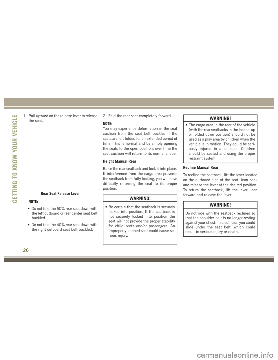
1. Pull upward on the release lever to releasethe seat.
NOTE:
• Do not fold the 60% rear seat down with the left outboard or rear center seat belt
buckled.
• Do not fold the 40% rear seat down with the right outboard seat belt buckled. 2. Fold the rear seat completely forward.
NOTE:
You may experience deformation in the seat
cushion from the seat belt buckles if the
seats are left folded for an extended period of
time. This is normal and by simply opening
the seats to the open position, over time the
seat cushion will return to its normal shape.
Height Manual Rear
Raise the rear seatback and lock it into place.
If interference from the cargo area prevents
the seatback from fully locking, you will have
difficulty returning the seat to its proper
position.
WARNING!
• Be certain that the seatback is securely
locked into position. If the seatback is
not securely locked into position the
seat will not provide the proper stability
for child seats and/or passengers. An
improperly latched seat could cause se-
rious injury.
WARNING!
• The cargo area in the rear of the vehicle(with the rear seatbacks in the locked-up
or folded down position) should not be
used as a play area by children when the
vehicle is in motion. They could be seri-
ously injured in a collision. Children
should be seated and using the proper
restraint system.
Recline Manual Rear
To recline the seatback, lift the lever located
on the outboard side of the seat, lean back
and release the lever at the desired position.
To return the seatback, lift the lever, lean
forward and release the lever.
WARNING!
Do not ride with the seatback reclined so
that the shoulder belt is no longer resting
against your chest. In a collision you could
slide under the seat belt, which could
result in serious injury or death.
Rear Seat Release Lever
GETTING TO KNOW YOUR VEHICLE
26
Page 29 of 372
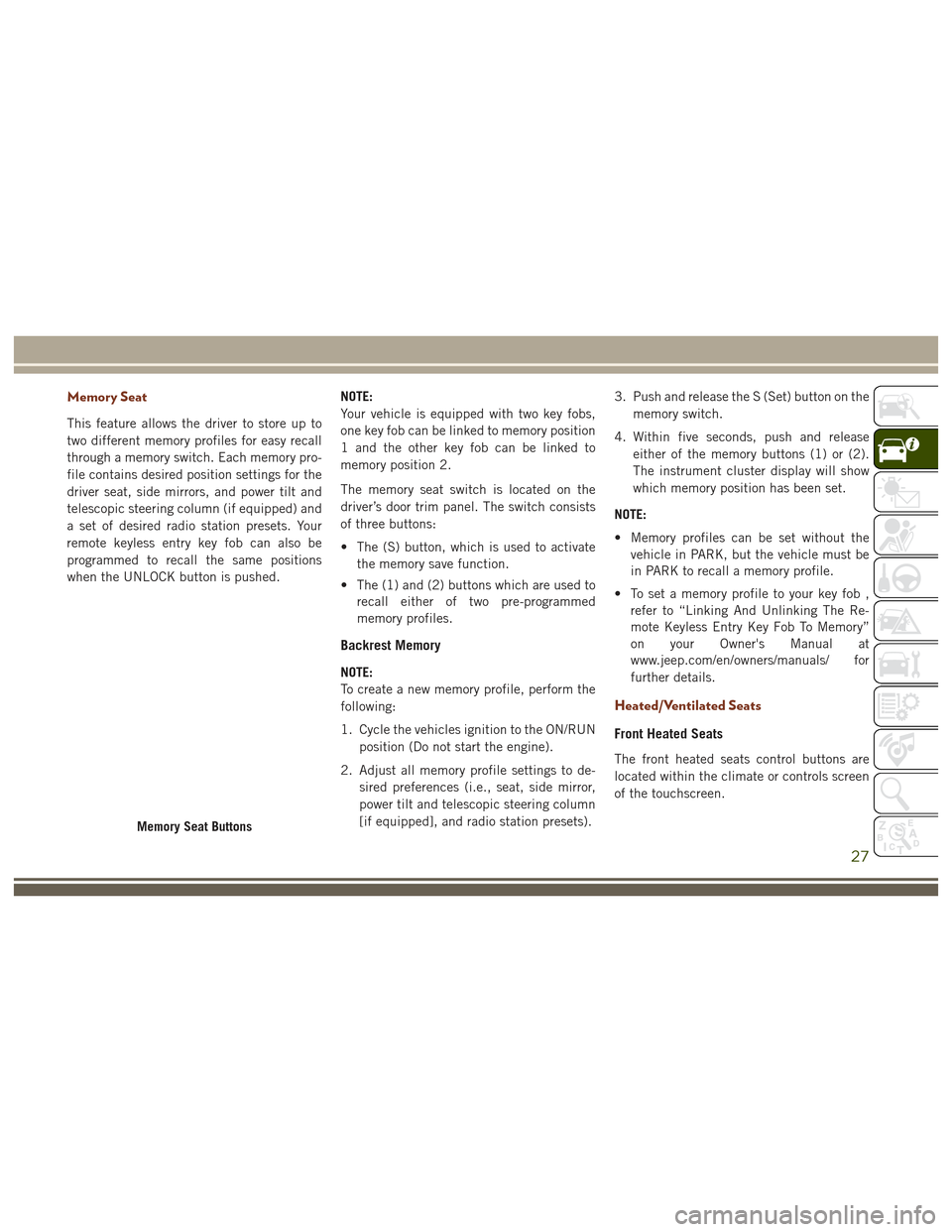
Memory Seat
This feature allows the driver to store up to
two different memory profiles for easy recall
through a memory switch. Each memory pro-
file contains desired position settings for the
driver seat, side mirrors, and power tilt and
telescopic steering column (if equipped) and
a set of desired radio station presets. Your
remote keyless entry key fob can also be
programmed to recall the same positions
when the UNLOCK button is pushed.NOTE:
Your vehicle is equipped with two key fobs,
one key fob can be linked to memory position
1 and the other key fob can be linked to
memory position 2.
The memory seat switch is located on the
driver’s door trim panel. The switch consists
of three buttons:
• The (S) button, which is used to activate
the memory save function.
• The (1) and (2) buttons which are used to recall either of two pre-programmed
memory profiles.
Backrest Memory
NOTE:
To create a new memory profile, perform the
following:
1. Cycle the vehicles ignition to the ON/RUN
position (Do not start the engine).
2. Adjust all memory profile settings to de- sired preferences (i.e., seat, side mirror,
power tilt and telescopic steering column
[if equipped], and radio station presets). 3. Push and release the S (Set) button on the
memory switch.
4. Within five seconds, push and release either of the memory buttons (1) or (2).
The instrument cluster display will show
which memory position has been set.
NOTE:
• Memory profiles can be set without the vehicle in PARK, but the vehicle must be
in PARK to recall a memory profile.
• To set a memory profile to your key fob , refer to “Linking And Unlinking The Re-
mote Keyless Entry Key Fob To Memory”
on your Owner's Manual at
www.jeep.com/en/owners/manuals/ for
further details.
Heated/Ventilated Seats
Front Heated Seats
The front heated seats control buttons are
located within the climate or controls screen
of the touchscreen.
Memory Seat Buttons
27
Page 34 of 372
WARNING!
the event of a collision and could result
in serious injury or death.
• Active Head Restraints may be deployed
if they are struck by an object such as a
hand, foot or loose cargo. To avoid acci-
dental deployment of the Active Head
Restraint ensure that all cargo is se-
cured, as loose cargo could contact the
Active Head Restraint during sudden
stops. Failure to follow this warning
could cause personal injury if the Active
Head Restraint is deployed.
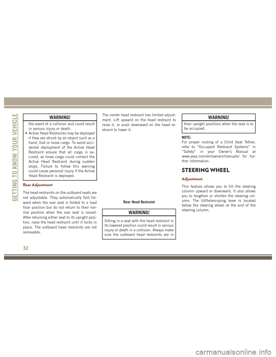
Rear Adjustment
The head restraints on the outboard seats are
not adjustable. They automatically fold for-
ward when the rear seat is folded to a load
floor position but do not return to their nor-
mal position when the rear seat is raised.
After returning either seat to its upright posi-
tion, raise the head restraint until it locks in
place. The outboard head restraints are not
removable. The center head restraint has limited adjust-
ment. Lift upward on the head restraint to
raise it, or push downward on the head re-
straint to lower it.
WARNING!
Sitting in a seat with the head restraint in
its lowered position could result in serious
injury or death in a collision. Always make
sure the outboard head restraints are in
WARNING!
their upright positions when the seat is to
be occupied.
NOTE:
For proper routing of a Child Seat Tether,
refer to “Occupant Restraint Systems” in
“Safety” in your Owner’s Manual at
www.jeep.com/en/owners/manuals/ for fur-
ther information.
STEERING WHEEL
Adjustment
This feature allows you to tilt the steering
column upward or downward. It also allows
you to lengthen or shorten the steering col-
umn. The tilt/telescoping lever is located
below the steering wheel at the end of the
steering column.
Rear Head RestraintGETTING TO KNOW YOUR VEHICLE
32
Page 35 of 372
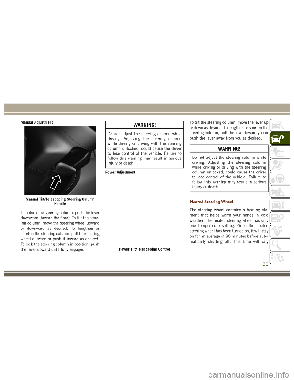
Manual Adjustment
To unlock the steering column, push the lever
downward (toward the floor). To tilt the steer-
ing column, move the steering wheel upward
or downward as desired. To lengthen or
shorten the steering column, pull the steering
wheel outward or push it inward as desired.
To lock the steering column in position, push
the lever upward until fully engaged.WARNING!
Do not adjust the steering column while
driving. Adjusting the steering column
while driving or driving with the steering
column unlocked, could cause the driver
to lose control of the vehicle. Failure to
follow this warning may result in serious
injury or death.
Power Adjustment To tilt the steering column, move the lever up
or down as desired. To lengthen or shorten the
steering column, pull the lever toward you or
push the lever away from you as desired.
WARNING!
Do not adjust the steering column while
driving. Adjusting the steering column
while driving or driving with the steering
column unlocked, could cause the driver
to lose control of the vehicle. Failure to
follow this warning may result in serious
injury or death.
Heated Steering Wheel
The steering wheel contains a heating ele-
ment that helps warm your hands in cold
weather. The heated steering wheel has only
one temperature setting. Once the heated
steering wheel has been turned on, it will stay
on for an average of 80 minutes before auto-
matically shutting off. This time will vary
Manual Tilt/Telescoping Steering Column
Handle
Power Tilt/Telescoping Control
33
Page 38 of 372
Folding Mirrors
All outside mirrors are hinged and may be
moved either forward or rearward to resist
damage. The hinges have three detent posi-
tions:
• Full forward position
• Full rearward position
• Normal position
Power Folding Mirrors — If Equipped
If equipped with power folding mirrors, they
can be electrically folded rearward and un-
folded into the drive position.
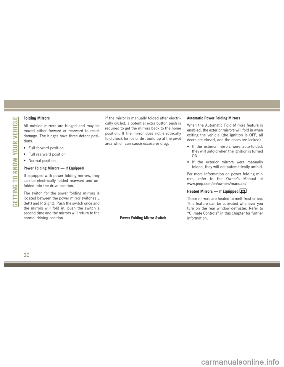
The switch for the power folding mirrors is
located between the power mirror switches L
(left) and R (right). Push the switch once and
the mirrors will fold in, push the switch a
second time and the mirrors will return to the
normal driving position.If the mirror is manually folded after electri-
cally cycled, a potential extra button push is
required to get the mirrors back to the home
position. If the mirror does not electrically
fold check for ice or dirt build up at the pivot
area which can cause excessive drag.
Automatic Power Folding Mirrors
When the Automatic Fold Mirrors feature is
enabled, the exterior mirrors will fold in when
exiting the vehicle (the ignition is OFF, all
doors are closed, and the doors are locked).
• If the exterior mirrors were auto-folded,
they will unfold when the ignition is turned
ON.
• If the exterior mirrors were manually folded, they will not automatically unfold.
For more information on power folding mir-
rors, refer to the Owner’s Manual at
www.jeep.com/en/owners/manuals/.
Heated Mirrors — If Equipped
These mirrors are heated to melt frost or ice.
This feature can be activated whenever you
turn on the rear window defroster. Refer to
“Climate Controls” in this chapter for further
information.
Power Folding Mirror Switch
GETTING TO KNOW YOUR VEHICLE
36
Page 39 of 372
EXTERIOR LIGHTS
Headlight Switch
The headlight switch is located on the left
side of the instrument panel, next to the
steering wheel. The headlight switch controls
the operation of the headlights, parking
lights, instrument panel lights, cargo lights
and fog lights (if equipped).
Headlights
To turn on the headlights, rotate the head-
light switch clockwise. When the headlight
switch is on, the parking lights, taillights,
license plate light and instrument panellights are also turned on. To turn off the
headlights, rotate the headlight switch back
to the O (Off) position.
NOTE:
• Your vehicle is equipped with plastic
headlight and fog light (if equipped)
lenses that are lighter and less susceptible
to stone breakage than glass lights. Plastic
is not as scratch resistant as glass and
therefore different lens cleaning proce-
dures must be followed.
• To minimize the possibility of scratching the lenses and reducing light output, avoid
wiping with a dry cloth. To remove road
dirt, wash with a mild soap solution fol-
lowed by rinsing.
CAUTION!
Do not use abrasive cleaning components,
solvents, steel wool or other abrasive ma-
terials to clean the lenses.
Headlight Switch
1 — Auto
2 — Rotate Headlight Switch
3 — Push Fog Lights
4 — Rotate Dimmer
37
Page 41 of 372
If the windshield or Automatic High Beam
Headlamp Control mirror is replaced, the
mirror must be re-aimed to ensure proper
performance. See your local authorized
dealer.
Parking Lights And Panel Lights
To turn on the parking lights and instrument
panel lights, rotate the headlight switch
clockwise. To turn off the parking lights,
rotate the headlight switch back to the O (Off)
position.
Headlight Delay
To aid in your exit, your vehicle is equipped
with a headlight delay that will leave the
headlights on for approximately up to 90 sec-
onds. This delay is initiated when the ignition
is turned OFF while the headlight switch is
on, and then the headlight switch is cycled
off. Headlight delay can be cancelled by
either turning the headlight switch on then
off, or by turning the ignition ON.NOTE:
This feature can be programmed through the
Uconnect system. Refer to “Uconnect Set-
tings” in “Multimedia” for further informa-
tion.
Fog Lights
The fog lights are turned on by rotating the
headlight switch to the parking light or head-
light position and pushing in the headlight
rotary control.
The fog lights will operate only when the
parking lights are on or when the vehicle
headlights are on low beam. An indicator
light located in the instrument cluster display
will illuminate when the fog lights are on. The
fog lights will turn off when the switch is
pushed a second time, when the headlight
switch is rotated to the off position, or the
high beam is selected.
Turn Signals
Move the multifunction lever up or down and
the arrows on each side of the instrument
cluster display flash to show proper operation
of the front and rear turn signal lights.
NOTE:
If either light remains on and does not flash,
or there is a very fast flash rate, check for a
defective outside light bulb. If an indicator
fails to light when the lever is moved, it would
suggest that the indicator bulb is defective.
Fog Light Operation
39