lock JEEP GRAND CHEROKEE 2017 WK2 / 4.G Service Manual
[x] Cancel search | Manufacturer: JEEP, Model Year: 2017, Model line: GRAND CHEROKEE, Model: JEEP GRAND CHEROKEE 2017 WK2 / 4.GPages: 372
Page 130 of 372
If A Deployment Occurs
The front air bags are designed to deflate
immediately after deployment.
NOTE:
Front and/or side air bags will not deploy in
all collisions. This does not mean something
is wrong with the air bag system.
If you do have a collision which deploys the
air bags, any or all of the following may occur:
• The air bag material may sometimes causeabrasions and/or skin reddening to the
occupants as the air bags deploy and un-
fold. The abrasions are similar to friction
rope burns or those you might get sliding
along a carpet or gymnasium floor. They
are not caused by contact with chemicals.
They are not permanent and normally heal
quickly. However, if you haven’t healed
significantly within a few days, or if you
have any blistering, see your doctor imme-
diately.
• As the air bags deflate, you may see some smoke-like particles. The particles are a
normal by-product of the process that gen-
erates the non-toxic gas used for air bag
inflation. These airborne particles may ir- ritate the skin, eyes, nose, or throat. If you
have skin or eye irritation, rinse the area
with cool water. For nose or throat irrita-
tion, move to fresh air. If the irritation
continues, see your doctor. If these par-
ticles settle on your clothing, follow the
garment manufacturer’s instructions for
cleaning.
Do not drive your vehicle after the air bags
have deployed. If you are involved in another
collision, the air bags will not be in place to
protect you.
WARNING!
Deployed air bags and seat belt preten-
sioners cannot protect you in another col-
lision. Have the air bags, seat belt preten-
sioners, and the seat belt retractor
assemblies replaced by an authorized
dealer immediately. Also, have the Occu-
pant Restraint Controller System serviced
as well. NOTE:
• Air bag covers may not be obvious in the
interior trim, but they will open during air
bag deployment.
• After any collision, the vehicle should be taken to an authorized dealer
immediately.
Enhanced Accident Response System
In the event of an impact, if the communica-
tion network remains intact, and the power
remains intact, depending on the nature of
the event, the ORC will determine whether to
have the Enhanced Accident Response Sys-
tem perform the following functions:
• Cut off fuel to the engine.
• Flash hazard lights as long as the batteryhas power or until the hazard light button
is pressed. The hazard lights can be deac-
tivated by pressing the hazard light but-
ton.
• Turn on the interior lights, which remain on as long as the battery has power.
• Unlock the power door locks.
SAFETY
128
Page 139 of 372
1. To access the center seat arm rest tether,first lower the arm rest. The tether is
located behind the armrest and hooked
onto the plastic seat backing.
2. Pull down on the tether to unhook it from the plastic seat backing.
3. Raise the armrest and attach the tether hook to the strap located on the front of
the arm rest.
Always follow the directions of the child re-
straint manufacturer when installing your
child restraint. Not all child restraint systems
will be installed as described here.
Center Arm Rest Tether
For rear-facing child restraints secured in the
center seat position with the vehicle seat
belts, the rear center seat position has an
armrest tether that secures the arm rest in the
upward position.
1. To access the center seat arm rest tether, first lower the arm rest. The tether is
located behind the armrest and hooked
onto the plastic seat backing. 2. Pull down on the tether to unhook it from
the plastic seat backing.
3. Raise the armrest and attach the tether hook to the strap located on the front of
the arm rest. Always follow the directions of the child re-
straint manufacturer when installing your
child restraint. Not all child restraint systems
will be installed as described here.
To Install A LATCH-Compatible Child Re-
straint
If the selected seating position has a Switch-
able Automatic Locking Retractor (ALR) seat
belt, stow the seat belt, following the instruc-
Center Seat Position Arm Rest TetherCenter Seat Position Arm Rest Tether At-
tached
137
Page 140 of 372
tions below. See the section “Installing Child
Restraints Using the Vehicle Seat Belt” to
check what type of seat belt each seating
position has.
1. Loosen the adjusters on the lower strapsand on the tether strap of the child seat so
that you can more easily attach the hooks
or connectors to the vehicle anchorages.
2. Place the child seat between the lower anchorages for that seating position. For
some second row seats, you may need to
recline the seat and / or raise the head
restraint to get a better fit. If the rear seat
can be moved forward and rearward in the
vehicle, you may wish to move it to its
rear-most position to make room for the
child seat. You may also move the front
seat forward to allow more room for the
child seat.
3. Attach the lower hooks or connectors of the child restraint to the lower anchorages
in the selected seating position.
4. If the child restraint has a tether strap, connect it to the top tether anchorage. See the section “Installing Child Re-
straints Using the Top Tether Anchorage”
for directions to attach a tether anchor.
5. Tighten all of the straps as you push the child restraint rearward and downward
into the seat. Remove slack in the straps
according to the child restraint manufac-
turer’s instructions.
6. Test that the child restraint is installed tightly by pulling back and forth on the
child seat at the belt path. It should not
move more than 1 inch (25.4 mm) in any
direction.
How To Stow An Unused Switchable-ALR
(ALR) Seat Belt
When using the LATCH attaching system to
install a child restraint, stow all ALR seat
belts that are not being used by other occu-
pants or being used to secure child restraints.
An unused belt could injure a child if they
play with it and accidentally lock the seat belt
retractor. Before installing a child restraint
using the LATCH system, buckle the seat belt
behind the child restraint and out of the
child’s reach. If the buckled seat belt inter-
feres with the child restraint installation, instead of buckling it behind the child re-
straint, route the seat belt through the child
restraint belt path and then buckle it. Do not
lock the seat belt. Remind all children in the
vehicle that the seat belts are not toys and
that they should not play with them.
WARNING!
• Improper installation of a child restraint
to the LATCH anchorages can lead to
failure of the restraint. The child could
be badly injured or killed. Follow the
child restraint manufacturer’s directions
exactly when installing an infant or child
restraint.
• Child restraint anchorages are designed
to withstand only those loads imposed
by correctly-fitted child restraints. Un-
der no circumstances are they to be
used for adult seat belts, harnesses, or
for attaching other items or equipment
to the vehicle.
SAFETY
138
Page 141 of 372
Installing Child Restraints Using The Ve-
hicle Seat Belt
Child restraint systems are designed to be
secured in vehicle seats by lap belts or the lap
belt portion of a lap/shoulder belt.
WARNING!
• Improper installation or failure to prop-erly secure a child restraint can lead to
failure of the restraint. The child could
be badly injured or killed.
• Follow the child restraint manufacturer’s
directions exactly when installing an in-
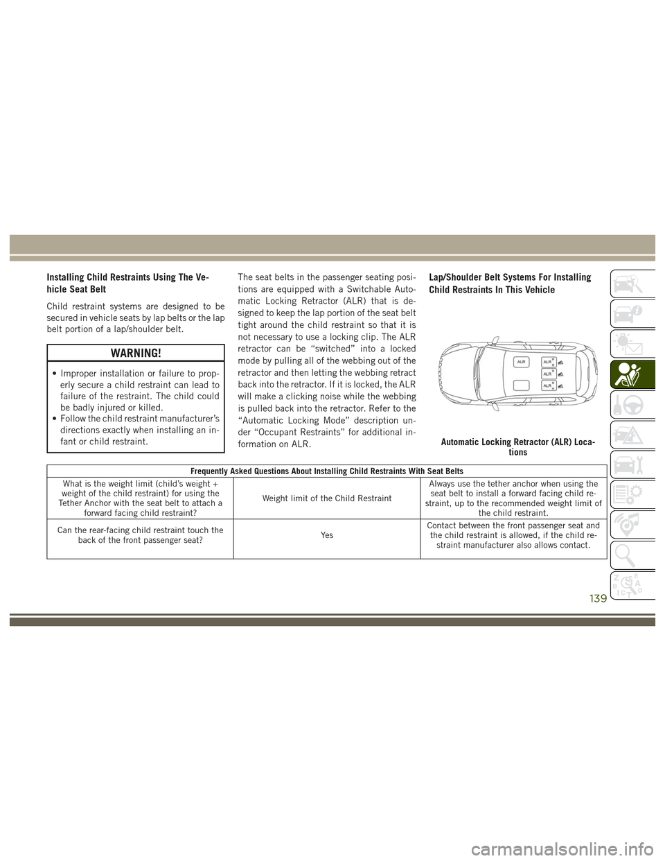
fant or child restraint. The seat belts in the passenger seating posi-
tions are equipped with a Switchable Auto-
matic Locking Retractor (ALR) that is de-
signed to keep the lap portion of the seat belt
tight around the child restraint so that it is
not necessary to use a locking clip. The ALR
retractor can be “switched” into a locked
mode by pulling all of the webbing out of the
retractor and then letting the webbing retract
back into the retractor. If it is locked, the ALR
will make a clicking noise while the webbing
is pulled back into the retractor. Refer to the
“Automatic Locking Mode” description un-
der “Occupant Restraints” for additional in-
formation on ALR.
Lap/Shoulder Belt Systems For Installing
Child Restraints In This Vehicle
Frequently Asked Questions About Installing Child Restraints With Seat Belts
What is the weight limit (child’s weight +
weight of the child restraint) for using the
Tether Anchor with the seat belt to attach a forward facing child restraint? Weight limit of the Child RestraintAlways use the tether anchor when using the
seat belt to install a forward facing child re-
straint, up to the recommended weight limit of the child restraint.
Can the rear-facing child restraint touch the back of the front passenger seat? Ye sContact between the front passenger seat and
the child restraint is allowed, if the child re- straint manufacturer also allows contact.
Automatic Locking Retractor (ALR) Loca- tions
139
Page 142 of 372
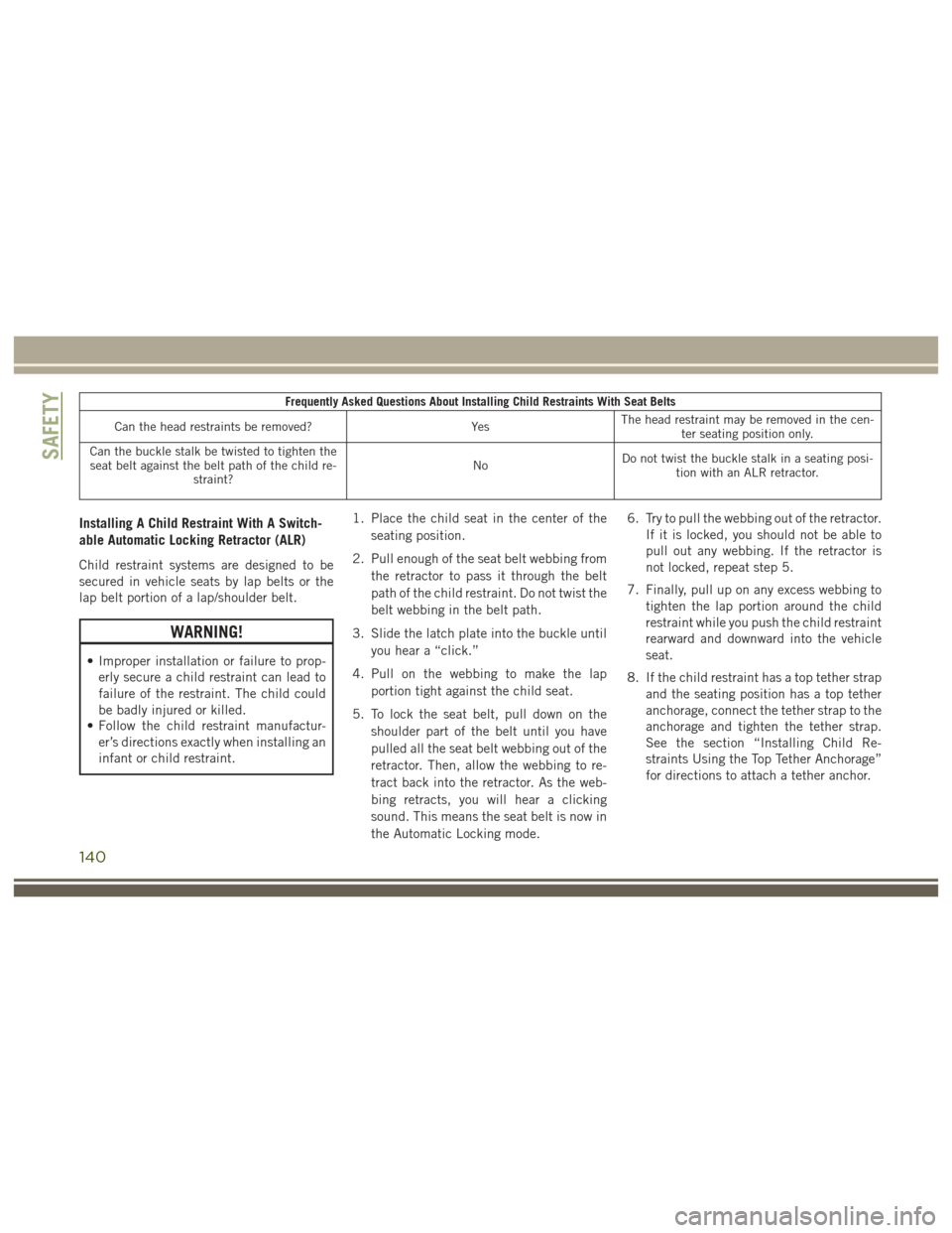
Frequently Asked Questions About Installing Child Restraints With Seat Belts
Can the head restraints be removed? YesThe head restraint may be removed in the cen-
ter seating position only.
Can the buckle stalk be twisted to tighten the seat belt against the belt path of the child re- straint? No
Do not twist the buckle stalk in a seating posi-
tion with an ALR retractor.
Installing A Child Restraint With A Switch-
able Automatic Locking Retractor (ALR)
Child restraint systems are designed to be
secured in vehicle seats by lap belts or the
lap belt portion of a lap/shoulder belt.
WARNING!
• Improper installation or failure to prop-
erly secure a child restraint can lead to
failure of the restraint. The child could
be badly injured or killed.
• Follow the child restraint manufactur-
er’s directions exactly when installing an
infant or child restraint. 1. Place the child seat in the center of the
seating position.
2. Pull enough of the seat belt webbing from the retractor to pass it through the belt
path of the child restraint. Do not twist the
belt webbing in the belt path.
3. Slide the latch plate into the buckle until you hear a “click.”
4. Pull on the webbing to make the lap portion tight against the child seat.
5. To lock the seat belt, pull down on the shoulder part of the belt until you have
pulled all the seat belt webbing out of the
retractor. Then, allow the webbing to re-
tract back into the retractor. As the web-
bing retracts, you will hear a clicking
sound. This means the seat belt is now in
the Automatic Locking mode. 6. Try to pull the webbing out of the retractor.
If it is locked, you should not be able to
pull out any webbing. If the retractor is
not locked, repeat step 5.
7. Finally, pull up on any excess webbing to tighten the lap portion around the child
restraint while you push the child restraint
rearward and downward into the vehicle
seat.
8. If the child restraint has a top tether strap and the seating position has a top tether
anchorage, connect the tether strap to the
anchorage and tighten the tether strap.
See the section “Installing Child Re-
straints Using the Top Tether Anchorage”
for directions to attach a tether anchor.
SAFETY
140
Page 147 of 372
WARNING!
clutch pedal (if present) to check for
interference. If your floor mat interferes
with the operation of any pedal, or is not
secure to the floor, remove the floor mat
from the vehicle and place the floor mat
in your trunk.
• ONLY use the passenger’s side floor mat
on the passenger’s side floor area.
• ALWAYS make sure objects cannot fall
or slide into the driver’s side floor area
when the vehicle is moving. Objects can
become trapped under accelerator,
brake, or clutch pedals and could cause
a loss of vehicle control.
• NEVER place any objects under the floor
mat (e.g., towels, keys, etc.). These ob-
jects could change the position of the
floor mat and may cause interference
with the accelerator, brake, or clutch
pedals.
• If the vehicle carpet has been removed
and re-installed, always properly attach
WARNING!
carpet to the floor and check the floor
mat fasteners are secure to the vehicle
carpet. Fully depress each pedal to
check for interference with the accelera-
tor, brake, or clutch pedals then re-
install the floor mats.
• It is recommended to only use mild soap
and water to clean your floor mats. After
cleaning, always check your floor mat
has been properly installed and is se-
cured to your vehicle using the floor mat
fasteners by lightly pulling mat.
Periodic Safety Checks You Should Make
Outside The Vehicle
Tires
Examine tires for excessive tread wear and
uneven wear patterns. Check for stones,
nails, glass, or other objects lodged in the
tread or sidewall. Inspect the tread for cuts and cracks. Inspect sidewalls for cuts,
cracks, and bulges. Check the wheel nuts for
tightness. Check the tires (including spare)
for proper cold inflation pressure.
Lights
Have someone observe the operation of brake
lights and exterior lights while you work the
controls. Check turn signal and high beam
indicator lights on the instrument panel.
Door Latches
Check for proper closing, latching, and lock-
ing.
Fluid Leaks
Check area under vehicle after overnight
parking for fuel, engine coolant, oil, or other
fluid leaks. Also, if gasoline fumes are de-
tected or if fuel, power steering fluid (if
equipped), or brake fluid leaks are sus-
pected. The cause should be located and
corrected immediately.
145
Page 149 of 372
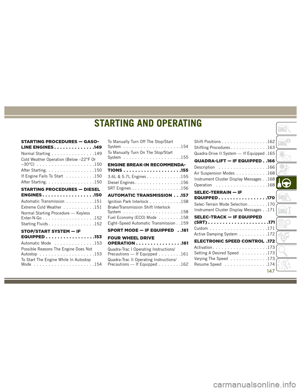
STARTING AND OPERATING
STARTING PROCEDURES — GASO-
LINEENGINES..............149
Normal Starting...............149
Cold Weather Operation (Below –22°F Or
−30°C) ....................150
After Starting .................150
If Engine Fails To Start ..........150
After Starting .................150
STARTING PROCEDURES — DIESEL
ENGINES................. .150
Automatic Transmission..........151
Extreme Cold Weather ...........151
Normal Starting Procedure — Keyless
Enter-N-Go ..................152
Starting Fluids ................152
STOP/START SYSTEM — IF
EQUIPPED................ .153
Automatic Mode..............153
Possible Reasons The Engine Does Not
Autostop ...................153
To Start The Engine While In Autostop
Mode .....................154 To Manually Turn Off The Stop/Start
System
....................154
To Manually Turn On The Stop/Start
System ....................155
ENGINE BREAK-IN RECOMMENDA-
TIONS................... .155
3.6L & 5.7L Engines............155
Diesel Engines ................156
SRT Engines .................156
AUTOMATIC TRANSMISSION . . .157
Ignition Park Interlock ...........158
Brake/Transmission Shift Interlock
System ....................158
Fuel Economy (ECO) Mode ........158
Eight–Speed Automatic Transmission . .159
SPORT MODE — IF EQUIPPED . .161
FOUR WHEEL DRIVE
OPERATION............... .161
Quadra-Trac I Operating Instructions/
Precautions — If Equipped........161
Quadra-Trac II Operating Instructions/
Precautions — If Equipped ........162Shift Positions
................162
Shifting Procedures .............163
Quadra-Drive II System — If Equipped .165
QUADRA-LIFT — IF EQUIPPED . .166
Description .................166
Air Suspension Modes ...........168
Instrument Cluster Display Messages . .168
Operation ..................168
SELEC-TERRAIN — IF
EQUIPPED................ .170
Selec-Terrain Mode Selection.......170
Instrument Cluster Display Messages . .171
SELEC-TRACK — IF EQUIPPED
(SRT).................... .171
Custom....................171
Active Damping System ..........172
ELECTRONIC SPEED CONTROL .172
Activation...................173
Setting A Desired Speed .........173
Varying The Speed .............173
Resume Speed ...............174
STARTING AND OPERATING
147
Page 151 of 372
STARTING PROCEDURES —
GASOLINE ENGINES
Before starting your vehicle, adjust your seat,
adjust the inside and outside mirrors, fasten
your seat belt, and if present, instruct all
other occupants to buckle their seat belts.
WARNING!
• Before exiting a vehicle, always shift theautomatic transmission into PARK and
apply the parking brake. Always make
sure the keyless ignition node is in the
“OFF” mode, remove the key fob from
the vehicle and lock the vehicle.
• Never leave children alone in a vehicle,
or with access to an unlocked vehicle.
Leaving children in a vehicle unattended
is dangerous for a number of reasons. A
child or others could be seriously or
fatally injured. Children should be
warned not to touch the parking brake,
brake pedal or the gear selector.
• Do not leave the key fob in or near the
vehicle, or in a location accessible to
children, and do not leave the ignition of
WARNING!
a vehicle equipped with Keyless Enter-
N-Go in the ACC or ON/RUN mode. A
child could operate power windows,
other controls, or move the vehicle.
• Do not leave children or animals inside
parked vehicles in hot weather. Interior
heat build-up may cause serious injury
or death.
Normal Starting
To Turn On The Engine Using The ENGINE START/
STOP Button
1. The transmission must be in PARK or NEUTRAL.
2. Press and hold the brake pedal while pushing the ENGINE START/STOP button
once.
3. The system takes over and attempts to start the vehicle. If the vehicle fails to
start, the starter will disengage automati-
cally after 10 seconds.
4. If you wish to stop the cranking of the engine prior to the engine starting, push
the button again. NOTE:
Normal starting of either a cold or a warm
engine is obtained without pumping or press-
ing the accelerator pedal.
To Turn Off The Engine Using ENGINE START/
STOP Button
1. Place the gear selector in PARK, then
push and release the ENGINE START/
STOP button.
2. The ignition will return to the OFF mode.
3. If the gear selector is not in PARK, the ENGINE START/STOP button must be
held for two seconds or three short pushes
in a row with the vehicle speed above
5 mph (8 km/h) before the engine will
shut off. The ignition will remain in the
ACC mode until the gear selector is in
PARK and the button is pushed twice to
the OFF mode. If the gear selector is not in
PARK and the ENGINE START/STOP but-
ton is pushed once, the instrument cluster
will display a “Vehicle Not In Park” mes-
sage and the engine will remain running.
Never leave a vehicle out of the PARK
position, or it could roll.
149
Page 152 of 372
NOTE:
If the ignition is left in the ACC or RUN
(engine not running) mode and the transmis-
sion is in PARK, the system will automatically
time out after 30 minutes of inactivity and
the ignition will cycle to the OFF mode.
ENGINE START/STOP Button Functions — With
Driver’s Foot OFF The Brake Pedal (In PARK Or
NEUTRAL Position)
The ENGINE START/STOP button operates
similar to an ignition switch. It has four
modes, OFF, ACC, RUN and START. To
change the ignition modes without starting
the vehicle and use the accessories follow
these steps:
• Starting with the ignition in the OFF mode,
• Push the ENGINE START/STOP buttononce to place the ignition to the ACC mode
(instrument cluster will display “ACC”),
• Push the ENGINE START/STOP button a second time to place the ignition to the
RUN mode (instrument cluster will display
“ON/RUN”), • Push the ENGINE START/STOP button a
third time to return the ignition to the OFF
mode (instrument cluster will display
“OFF”).
Cold Weather Operation (Below –22°F Or
−30°C)
To ensure reliable starting at these tempera-
tures, use of an externally powered electric
engine block heater (available from your Au-
thorized Dealer) is recommended.
After Starting
The idle speed is controlled automatically,
and it will decrease as the engine warms up.
If Engine Fails To Start
WARNING!
• Never pour fuel or other flammable liq-uid into the throttle body air inlet open-
ing in an attempt to start the vehicle.
This could result in flash fire causing
serious personal injury.
• Do not attempt to push or tow your
vehicle to get it started. Vehicles
WARNING!
equipped with an automatic transmis-
sion cannot be started this way. Un-
burned fuel could enter the catalytic
converter and once the engine has
started, ignite and damage the converter
and vehicle.
• If the vehicle has a discharged battery,
booster cables may be used to obtain a
start from a booster battery or the battery
in another vehicle. This type of start can
be dangerous if done improperly. Refer
to “Jump-Starting” in “In Case Of Emer-
gency” for further information.
After Starting
The idle speed is controlled automatically,
and it will decrease as the engine warms up.
STARTING PROCEDURES —
DIESEL ENGINES
Before starting your vehicle, adjust your seat,
both inside and outside mirrors, and fasten
your seat belts.
STARTING AND OPERATING
150
Page 153 of 372
The starter is allowed to crank for up to
30-second intervals. Waiting a few minutes
between such intervals will protect the starter
from overheating.
WARNING!
• Before exiting a vehicle, always shift theautomatic transmission into PARK and
apply the parking brake. Always make
sure the keyless ignition node is in the
“OFF” mode, remove the key fob from
the vehicle and lock the vehicle.
• Never leave children alone in a vehicle,
or with access to an unlocked vehicle.
Leaving children in a vehicle unattended
is dangerous for a number of reasons. A
child or others could be seriously or
fatally injured. Children should be
warned not to touch the parking brake,
brake pedal or the gear selector.
• Do not leave the key fob in or near the
vehicle, or in a location accessible to
children, and do not leave the ignition of
a vehicle equipped with Keyless Enter-
N-Go in the ACC or ON/RUN mode. A
WARNING!
child could operate power windows,
other controls, or move the vehicle.
• Do not leave children or animals inside
parked vehicles in hot weather. Interior
heat build-up may cause serious injury
or death.
NOTE:
Engine start up in very low ambient tempera-
ture could result in evident white smoke. This
condition will disappear as the engine warms
up.
CAUTION!
• The engine is allowed to crank as long as 30 seconds. If the engine fails to start
during this period, please wait at least
two minutes for the starter to cool before
repeating start procedure.
• If the “Water in Fuel Indicator Light”
remains on, DO NOT START engine be-
fore you drain the water from the fuel
filters to avoid engine damage. Refer to
“Draining Fuel/Water Separator Filter”
CAUTION!
in “Servicing And Maintenance” for fur-
ther information.
Automatic Transmission
Start the engine with the transmission gear
selector in the PARK position. Apply the
brake before shifting to any driving range.
Extreme Cold Weather
The engine block heater is a resistance heater
installed in the water jacket of the engine. It
requires a 110–115 Volt AC electrical outlet
with a grounded, three-wire extension cord.
Its use is recommended for environments
that routinely fall below -10°F (-23°C). It
should be used when the vehicle has not been
running overnight or longer periods and
should be plugged in two hours prior to start.
Its use is required for cold starts with tem-
peratures under -20°F (-28°C).
151