radio JEEP GRAND CHEROKEE 2017 WK2 / 4.G Owner's Manual
[x] Cancel search | Manufacturer: JEEP, Model Year: 2017, Model line: GRAND CHEROKEE, Model: JEEP GRAND CHEROKEE 2017 WK2 / 4.GPages: 372
Page 112 of 372
is then followed by a graphic display, with “-
-“ in place of the pressure value(s), indicat-
ing which Tire Pressure Monitoring Sensor(s)
is not being received.
If the ignition switch is cycled, this sequence
will repeat, providing the system fault still
exists. If the system fault no longer exists, the
Tire Pressure Monitoring Telltale Light will no
longer flash, the "SERVICE TPM SYSTEM"
message will not be present, and a pressure
value will be displayed instead of dashes. A
system fault can occur by any of the follow-
ing:
• Jamming due to electronic devices or driv-ing next to facilities emitting the same
Radio Frequencies as the TPM sensors.
• Installing some form of aftermarket win- dow tinting that affects radio wave signals.
• Lots of snow or ice around the wheels or wheel housings.
• Using tire chains on the vehicle.
• Using wheels/tires not equipped with TPM sensors. NOTE:
There is no tire pressure monitoring sensor in
the spare tire. The TPMS will not be able to
monitor the tire pressure. If you install the
spare tire in place of a road tire that has a
pressure below the low-pressure warning
limit, upon the next ignition switch cycle, the
Tire Pressure Monitoring Telltale Light will
remain ON, a chime will sound, and the
instrument cluster display will still display a
pressure value in the different color graphic
display and an "Inflate to XXX kPa" message
will be displayed. After driving the vehicle for
up to 20 minutes above 15 mph (24 km/h),
the Tire Pressure Monitoring Telltale Light
will flash on and off for 75 seconds and then
remain on solid. In addition, the instrument
cluster display will display a “SERVICE TPM
SYSTEM" message for five seconds and then
display dashes (- -) in place of the pressure
value. For each subsequent ignition switch
cycle, a chime will sound, the Tire Pressure
Monitoring Telltale Light will flash on and off
for 75 seconds and then remain on solid, and
the instrument cluster display will display a
"SERVICE TPM SYSTEM" message for five
seconds and then display dashes (- -) in place of the pressure value. Once you repair or
replace the original road tire, and reinstall it
on the vehicle in place of the spare tire, the
TPMS will update automatically.
In addition, the Tire Pressure Monitoring Tell-
tale Light will turn OFF and the graphic in the
instrument cluster display will display a new
pressure value instead of dashes (- -), as long
as no tire pressure is below the low-pressure
warning limit in any of the four active road
tires. The vehicle may need to be driven for
up to 20 minutes above 15 mph (24 km/h) in
order for the TPMS to receive this informa-
tion.
TPMS Deactivation — If Equipped
The TPMS can be deactivated if replacing all
four wheel and tire assemblies (road tires)
with wheel and tire assemblies that do not
have TPMS Sensors, such as when installing
winter wheel and tire assemblies on your
vehicle.
To deactivate the TPMS, first, replace all four
wheel and tire assemblies (road tires) with
tires not equipped with Tire Pressure Moni-
toring (TPM) Sensors. Then, drive the vehicle
SAFETY
110
Page 113 of 372
for 10 minutes above 15 mph (24 km/h). The
TPMS will chime, the "TPM Telltale Light"
will flash on and off for 75 seconds and then
remain on. The instrument cluster will dis-
play the “SERVICE TPM SYSTEM” message
and then display dashes (--) in place of the
pressure values.
Beginning with the next ignition cycle, the
TPMS will no longer chime or display the
“SERVICE TPM SYSTEM” message in the
instrument cluster but dashes (--) will remain
in place of the pressure values.
To reactivate the TPMS, replace all four
wheel and tire assemblies (road tires) with
tires equipped with TPM sensors. Then, drive
the vehicle for up to 10 minutes above
15 mph (24 km/h). The TPMS will chime, the
"TPM Telltale Light" will flash on and off for
75 seconds and then turn off. The instrument
cluster will display the “SERVICE TPM SYS-
TEM” message and then display pressure
values in place of the dashes. On the next
ignition cycle the "SERVICE TPM SYSTEM"
message will no longer be displayed as long
as no system fault exists.General Information
The following regulatory statement applies to
all radio frequency (RF) devices equipped in
this vehicle:
This device complies with Part 15 of the FCC
Rules and with Industry Canada license-
exempt RSS standard(s). Operation is sub-
ject to the following two conditions:
(1) This device may not cause harmful inter-
ference, and
(2) This device must accept any interference
received, including interference that may
cause undesired operation.
NOTE:
Changes or modifications not expressly ap-
proved by the party responsible for compli-
ance could void the user’s authority to oper-
ate the equipment.
OCCUPANT RESTRAINT
SYSTEMS
Some of the most important safety features in
your vehicle are the restraint systems:
Occupant Restraint Systems Features
• Seat Belt Systems
• Supplemental Restraint Systems (SRS)Air Bags
• Supplemental Active Head Restraints
• Child Restraints
Some of the safety features described in this
section may be standard equipment on some
models, or may be optional equipment on
others. If you are not sure, ask your autho-
rized dealer.
Important Safety Precautions
Please pay close attention to the information
in this section. It tells you how to use your
restraint system properly, to keep you and
your passengers as safe as possible.
Here are some simple steps you can take to
minimize the risk of harm from a deploying
air bag:
1. Children 12 years old and under should always ride buckled up in a vehicle with a
rear seat.
111
Page 126 of 372
WARNING!
are designed to open only when the air
bags are inflating.
• Relying on the air bags alone could lead
to more severe injuries in a collision. The
air bags work with your seat belt to
restrain you properly. In some collisions,
air bags won’t deploy at all. Always wear
your seat belts even though you have air
bags.
Front Air Bag Operation
Front Air Bags are designed to provide addi-
tional protection by supplementing the seat
belts. Front air bags are not expected to
reduce the risk of injury in rear, side, or
rollover collisions. The front air bags will not
deploy in all frontal collisions, including
some that may produce substantial vehicle
damage — for example, some pole collisions,
truck underrides, and angle offset collisions.
On the other hand, depending on the type
and location of impact, front air bags may
deploy in crashes with little vehicle front-end
damage but that produce a severe initial
deceleration. Because air bag sensors measure vehicle
deceleration over time, vehicle speed and
damage by themselves are not good indica-
tors of whether or not an air bag should have
deployed.
Seat belts are necessary for your protection in
all collisions, and also are needed to help
keep you in position, away from an inflating
air bag.
When the ORC detects a collision requiring
the front air bags, it signals the inflator units.
A large quantity of non-toxic gas is generated
to inflate the front air bags.
The steering wheel hub trim cover and the
upper right side of the instrument panel
separate and fold out of the way as the air
bags inflate to their full size. The front air
bags fully inflate in less time than it takes to
blink your eyes. The front air bags then
quickly deflate while helping to restrain the
driver and front passenger.
Knee Impact Bolsters
The Knee Impact Bolsters help protect the
knees of the driver and front passenger, and
position the front occupants for improved
interaction with the front air bags.
WARNING!
• Do not drill, cut, or tamper with the knee
impact bolsters in any way.
• Do not mount any accessories to the
knee impact bolsters such as alarm
lights, stereos, citizen band radios, etc.
Supplemental Driver Knee Air Bag
This vehicle is equipped with a Supplemental
Driver Knee Air Bag mounted in the instru-
ment panel below the steering column. The
Supplemental Driver Knee Air Bag provides
enhanced protection during a frontal impact
by working together with the seat belts, pre-
tensioners, and front air bags.
SAFETY
124
Page 169 of 372
(40 km/h) the vehicle height will be auto-
matically lowered to OR1. Refer to “Driv-
ing Tips” in “Starting And Operating” for
further information.
• Aero Mode (Lowers the vehicle approxi-
mately 0.6 inches (15 mm) – This position
provides improved aerodynamics by lower-
ing the vehicle. The vehicle will automati-
cally enter Aero Mode when the vehicle
speed remains between 52 mph (83 km/h)
and 56 mph (90 km/h) for greater than
20 seconds or if the vehicle speed exceeds
56 mph (90 km/h). The vehicle will return
to NRH from Aero Mode if the vehicle
speed remains between 20 mph (32 km/h)
and 25 mph (40 km/h) for greater than
20 seconds or if the vehicle speed falls
below 20 mph (32 km/h). The vehicle will
enter Aero Mode, regardless of vehicle
speed if the vehicle is in “SPORT” mode.
• Entry/Exit Mode (Lowers the vehicle approxi-
mately 1.6 inces (40 mm) – This position
lowers the vehicle for easier passenger
entry and exit as well as lowering the rear
of the vehicle for easier loading and un-
loading of cargo. To enter Entry/Exit Mode,
push the “DOWN” button once from (NRH) while the vehicle speed is below
25 mph (40 km/h). Once the vehicle
speed goes below 15 mph (24 km/h) the
vehicle height will begin to lower. If the
vehicle speed remains between 15 mph
(24 km/h) and 25 mph (40 km/h) for
greater than 60 seconds, or the vehicle
speed exceeds 25 mph (40 km/h) the
Entry/Exit Mode change will be cancelled.
To exit Entry/Exit Mode, press the “Up”
button once while in Entry/Exit Mode or
drive the vehicle over 15 mph (24 km/h).
NOTE:
Automatic lowering of the vehicle into Entry/
Exit Mode can be enabled through the
Uconnect Touch-Screen Radio. If this feature
is enabled, the vehicle will only lower if the
gear selector is in "PARK", the terrain switch
is in "AUTO", the transfer-case is in "AUTO”
and the vehicle level should be either in
Normal or Aero Mode. The Vehicle will not
automatically lower if the air suspension level
is in Off Rd 2 or Off Rd 1. If the vehicle is
equipped with Intrusion Theft Module (ITM),
the lowering will be suppressed when the
ignition is switched OFF and the door is open
to prevent setting the alarm off. The Selec-Terrain switch will automatically
change the vehicle to the proper height based
on the position of the Selec-Terrain switch.
The height can be changed from the default
Selec-Terrain setting by normal use of the air
suspension buttons. Refer to “Selec-Terrain”
in “Starting And Operating” for further infor-
mation.
The system requires that the engine be run-
ning for all changes. When lowering the ve-
hicle all of the doors, including the liftgate,
must be closed. If a door is opened at any
time while the vehicle is lowering the change
will not be completed until the open door(s) is
closed.
The Quadra-Lift air suspension system uses a
lifting and lowering pattern which keeps the
headlights from incorrectly shining into on-
coming traffic. When raising the vehicle, the
rear of the vehicle will move up first and then
the front. When lowering the vehicle, the
front will move down first and then the rear.
167
Page 170 of 372
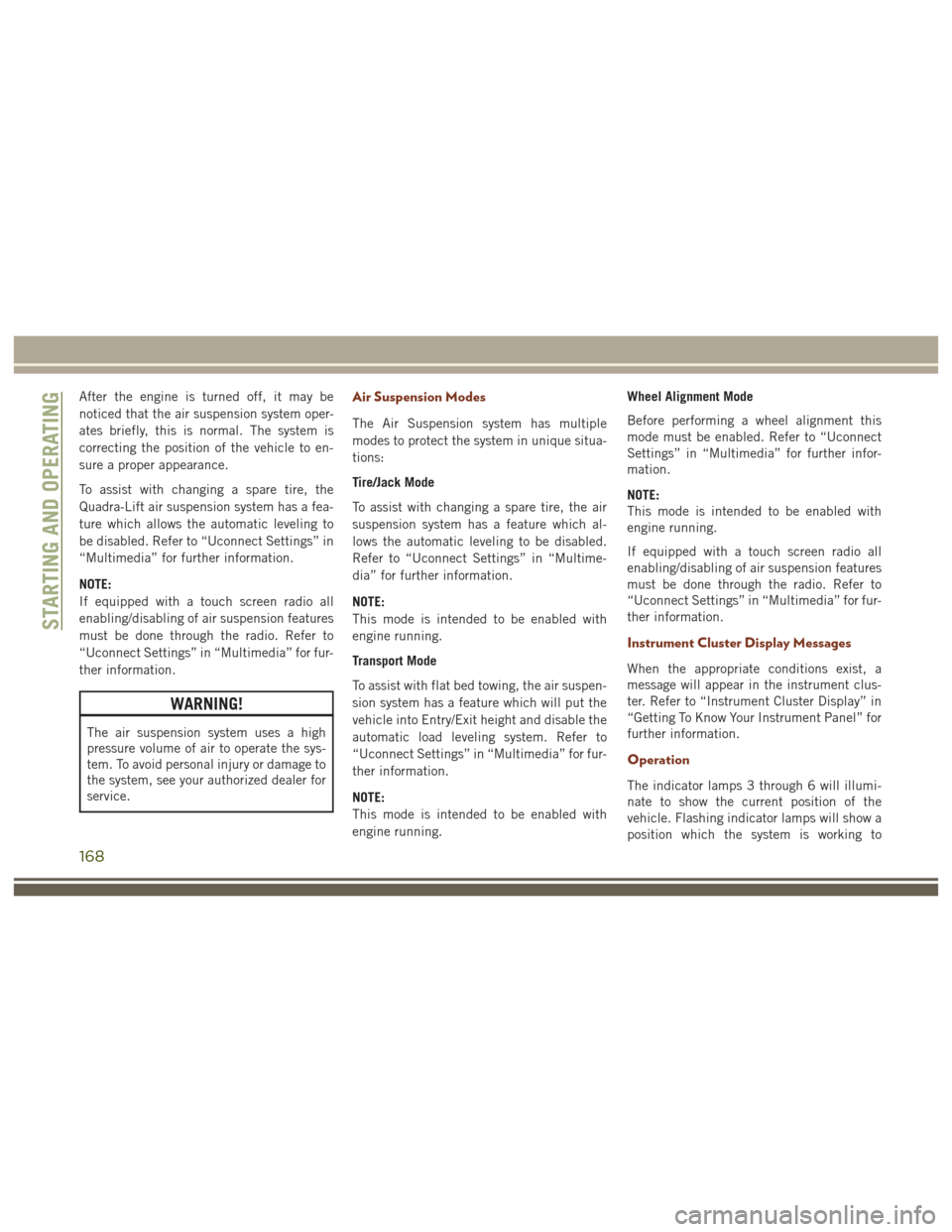
After the engine is turned off, it may be
noticed that the air suspension system oper-
ates briefly, this is normal. The system is
correcting the position of the vehicle to en-
sure a proper appearance.
To assist with changing a spare tire, the
Quadra-Lift air suspension system has a fea-
ture which allows the automatic leveling to
be disabled. Refer to “Uconnect Settings” in
“Multimedia” for further information.
NOTE:
If equipped with a touch screen radio all
enabling/disabling of air suspension features
must be done through the radio. Refer to
“Uconnect Settings” in “Multimedia” for fur-
ther information.
WARNING!
The air suspension system uses a high
pressure volume of air to operate the sys-
tem. To avoid personal injury or damage to
the system, see your authorized dealer for
service.
Air Suspension Modes
The Air Suspension system has multiple
modes to protect the system in unique situa-
tions:
Tire/Jack Mode
To assist with changing a spare tire, the air
suspension system has a feature which al-
lows the automatic leveling to be disabled.
Refer to “Uconnect Settings” in “Multime-
dia” for further information.
NOTE:
This mode is intended to be enabled with
engine running.
Transport Mode
To assist with flat bed towing, the air suspen-
sion system has a feature which will put the
vehicle into Entry/Exit height and disable the
automatic load leveling system. Refer to
“Uconnect Settings” in “Multimedia” for fur-
ther information.
NOTE:
This mode is intended to be enabled with
engine running.Wheel Alignment Mode
Before performing a wheel alignment this
mode must be enabled. Refer to “Uconnect
Settings” in “Multimedia” for further infor-
mation.
NOTE:
This mode is intended to be enabled with
engine running.
If equipped with a touch screen radio all
enabling/disabling of air suspension features
must be done through the radio. Refer to
“Uconnect Settings” in “Multimedia” for fur-
ther information.
Instrument Cluster Display Messages
When the appropriate conditions exist, a
message will appear in the instrument clus-
ter. Refer to “Instrument Cluster Display” in
“Getting To Know Your Instrument Panel” for
further information.
Operation
The indicator lamps 3 through 6 will illumi-
nate to show the current position of the
vehicle. Flashing indicator lamps will show a
position which the system is working to
STARTING AND OPERATING
168
Page 181 of 372
WARNING!
modes function differently. Always con-
firm which mode is selected.
PARKSENSE REAR PARK
ASSIST
ParkSense Sensors
The four ParkSense sensors, located in the
rear fascia/bumper, monitor the area behind
the vehicle that is within the sensors’ field of
view. The sensors can detect obstacles from
approximately 12 in (30 cm) up to 79 in
(200 cm) from the rear fascia/bumper in the
horizontal direction, depending on the loca-
tion, type and orientation of the obstacle.
Activation/Deactivation ParkSense
ParkSense can be enabled and disabled with
the ParkSense switch.
When the ParkSense switch is pushed to
disable the system, the instrument cluster
display will show the “PARKSENSE OFF”
message for approximately five seconds. Re-
fer to “Instrument Cluster Display” in “Get-ting To Know Your Instrument Panel” for
further information. When the gear selector is
moved to REVERSE and the system is dis-
abled, the instrument cluster display will
show the “PARKSENSE OFF” message for as
long as the vehicle is in REVERSE.
The ParkSense switch LED will be ON when
ParkSense is disabled or requires service.
The ParkSense switch LED will be OFF when
the system is enabled. If the ParkSense
switch is pushed, and the system requires
service, the ParkSense switch LED will blink
momentarily, and then the LED will be ON.
Instrument Cluster Display
The ParkSense Warning screen will only be
displayed if Sound and Display is selected
from the Customer - Programmable Features
section of the Uconnect System. Refer to
"Uconnect Settings” in “Multimedia” for fur-
ther information.
The ParkSense Warning screen is located
within the instrument cluster display. It pro-
vides visual warnings to indicate the distance
between the rear fascia/bumper and the de-
tected obstacle. Refer to “Instrument Cluster
Display” in “Getting To Know Your Instru-
ment Panel for further information.
ParkSense System Usage Precautions
NOTE:
• Ensure that the rear bumper is free of
snow, ice, mud, dirt and debris to keep the
ParkSense system operating properly.
• Jackhammers, large trucks, and other vi- brations could affect the performance of
ParkSense.
• When you turn ParkSense OFF, the instru- ment cluster display will read
“PARKSENSE OFF”. Furthermore, once
you turn ParkSense off, it remains off until
you turn it on again, even if you cycle the
ignition.
• When you move the gear selector to the REVERSE position and ParkSense is
turned OFF, the instrument cluster display
will show a “PARKSENSE OFF” message
for as long as the vehicle is in REVERSE.
• ParkSense, when on, will reduce the vol- ume of the radio when it is sounding a
tone.
179
Page 224 of 372
WARNING!
• Take care to avoid the radiator coolingfan whenever the hood is raised. It can
start anytime the ignition switch is ON.
You can be injured by moving fan
blades.
WARNING!
• Remove any metal jewelry such as rings,watch bands and bracelets that could
make an inadvertent electrical contact.
You could be seriously injured.
• Batteries contain sulfuric acid that can
burn your skin or eyes and generate
hydrogen gas which is flammable and
explosive. Keep open flames or sparks
away from the battery.
NOTE:
Be sure that the disconnected ends of the
cables do not touch while still connected to
the either vehicle.
1. Set the parking brake, shift the automatic transmission into PARK and turn the igni-
tion to LOCK.
2. Turn off the heater, radio, and all unnec- essary electrical accessories.
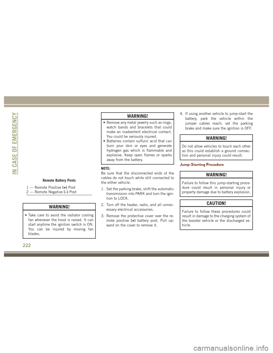
3. Remove the protective cover over the re- mote positive (+)battery post. Pull up-
ward on the cover to remove it. 4. If using another vehicle to jump-start the
battery, park the vehicle within the
jumper cables reach, set the parking
brake and make sure the ignition is OFF.
WARNING!
Do not allow vehicles to touch each other
as this could establish a ground connec-
tion and personal injury could result.
Jump-Starting Procedure
WARNING!
Failure to follow this jump-starting proce-
dure could result in personal injury or
property damage due to battery explosion.
CAUTION!
Failure to follow these procedures could
result in damage to the charging system of
the booster vehicle or the discharged ve-
hicle.
Remote Battery Posts
1 — Remote Positive (+)Post
2 — Remote Negative (–)Post
IN CASE OF EMERGENCY
222
Page 287 of 372
MULTIMEDIA
CYBERSECURITY............287
OFFROADPAGES—IF
EQUIPPED................ .288
Off Road Pages Status Bar........288
Drivetrain ...................288
Suspension ..................289
Accessory Gauges ..............289
Selec-Terrain .................289
TIPS CONTROLS AND GENERAL
INFORMATION ............ .290
Steering Wheel Audio Controls ......290
Reception Conditions ............290
Care And Maintenance ...........290
Anti-theft Protection ............291
UCONNECT ACCESS .........291
Uconnect Access — If Equipped (Available
On Uconnect 8.4/8.4 NAV — U.S.
Residents Only)...............291
Uconnect Access Registration (Uconnect
8.4/8.4 NAV, U.S. 48 Contiguous States,
Alaska And Hawaii) ............293
Download The Uconnect Access App . .293 Via Mobile Apps — If Equipped
.....294
Vehicle Finder ................295
Send&Go ..................296
Renewing Subscriptions And
Purchasing 3G Wi-Fi Hotspot (Uconnect
8.4/8.4 NAV, U.S. 48 Contiguous States,
Alaska And Hawaii) .............296
Getting Started With Apps ........297
Maintaining Your Uconnect Access
Account ....................298
Built-In Features ..............298
Vehicle Health Report/Alert ........301
Uconnect Access Remote Features . . .301
UCONNECT 5.0 .............305
Controls On The Front Panel .......305
Clock Setting .................306
Equalizer, Balance And Fade .......306
Radio Mode ..................307
Media Mode .................307
Bluetooth Source ..............310
iPod/USB/SD Card/AUX/Media Player
Control Support ...............311 USB/Audio Jack (AUX)/Bluetooth
Operation
...................311
Phone Mode .................312
SiriusXM Premier Over 160 Channels . .315
UCONNECT 8.4/8.4 NAV ......316
Uconnect 8.4/8.4 NAV At A Glance . . .316
Personalized Menu Bar...........318
Radio Mode ..................318
SiriusXM Premier Over 160 Channels .319
UCONNECT TOUCH SETTINGS . .322
IPOD/USB/SD CARD/MEDIA
PLAYERCONTROL ..........322
Audio Jack (AUX) ..............323
USB Port ...................323
SD Card ....................323
Bluetooth Streaming Audio ........323
Media Controls ................324
UCONNECT REAR SEAT ENTER-
TAINMENT (RSE) SYSTEM — IF
EQUIPPED................ .324
Getting Started...............324
MULTIMEDIA
285
Page 288 of 372
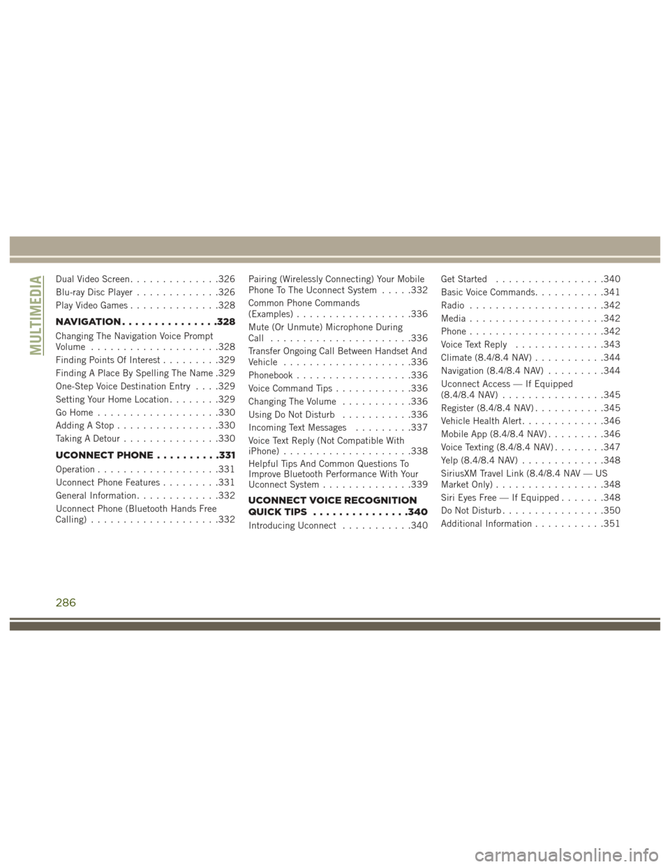
Dual Video Screen..............326
Blu-ray Disc Player .............326
Play Video Games ..............328
NAVIGATION.............. .328
Changing The Navigation Voice Prompt
Volume....................328
Finding Points Of Interest .........329
Finding A Place By Spelling The Name .329
One-Step Voice Destination Entry . . . .329
Setting Your Home Location ........329
Go Home ...................330
Adding A Stop ................330
Taking A Detour ...............330
UCONNECT PHONE ..........331
Operation...................331
Uconnect Phone Features .........331
General Information .............332
Uconnect Phone (Bluetooth Hands Free
Calling) ....................332 Pairing (Wirelessly Connecting) Your Mobile
Phone To The Uconnect System
.....332
Common Phone Commands
(Examples) ..................336
Mute (Or Unmute) Microphone During
Call ......................336
Transfer Ongoing Call Between Handset And
Vehicle ....................336
Phonebook ..................336
Voice Command Tips ............336
Changing The Volume ...........336
Using Do Not Disturb ...........336
Incoming Text Messages .........337
Voice Text Reply (Not Compatible With
iPhone) ....................338
Helpful Tips And Common Questions To
Improve Bluetooth Performance With Your
Uconnect System ..............339
UCONNECT VOICE RECOGNITION
QUICKTIPS ...............340
Introducing Uconnect ...........340 Get Started
.................340
Basic Voice Commands ...........341
Radio .....................342
Media .....................342
Phone .....................342
Voice Text Reply ..............343
Climate (8.4/8.4 NAV) ...........344
Navigation (8.4/8.4 NAV) .........344
Uconnect Access — If Equipped
(8.4/8.4 NAV) ................345
Register (8.4/8.4 NAV) ...........345
Vehicle Health Alert .............346
Mobile App (8.4/8.4 NAV) .........346
Voice Texting (8.4/8.4 NAV) ........347
Yelp (8.4/8.4 NAV) .............348
SiriusXM Travel Link (8.4/8.4 NAV — US
Market Only) .................348
Siri Eyes Free — If Equipped .......348
Do Not Disturb ................350
Additional Information ...........351
MULTIMEDIA
286
Page 289 of 372
CYBERSECURITY
Your vehicle may be a connected vehicle and
may be equipped with both wired and wire-
less networks. These networks allow your ve-
hicle to send and receive information. This
information allows systems and features in
your vehicle to function properly.
Your vehicle may be equipped with certain
security features to reduce the risk of unau-
thorized and unlawful access to vehicle sys-
tems and wireless communications. Vehicle
software technology continues to evolve over
time and FCA US LLC, working with its sup-
pliers, evaluates and takes appropriate steps
as needed. Similar to a computer or other
devices, your vehicle may require software
updates to improve the usability and perfor-
mance of your systems or to reduce the po-
tential risk of unauthorized and unlawful ac-
cess to your vehicle systems.
The risk of unauthorized and unlawful access
to your vehicle systems may still exist, even if
the most recent version of vehicle software
(such as Uconnect software) is installed.
WARNING!
• It is not possible to know or to predict allof the possible outcomes if your vehi-
cle’s systems are breached. It may be
possible that vehicle systems, including
safety related systems, could be im-
paired or a loss of vehicle control could
occur that may result in an accident
involving serious injury or death.
• ONLY insert media (e.g., USB, SD card,
or CD) into your vehicle if it came from a
trusted source. Media of unknown origin
could possibly contain malicious soft-
ware, and if installed in your vehicle, it
may increase the possibility for vehicle
systems to be breached.
• As always, if you experience unusual
vehicle behavior, take your vehicle to
your nearest authorized dealer immedi-
ately.
NOTE:
• FCA US LLC or your dealer may contact you directly regarding software updates. • To help further improve vehicle security
and minimize the potential risk of a secu-
rity breach, vehicle owners should:–Routinely check
www.driveuconnect.com/
software-update to learn about avail-
able Uconnect software updates.
– Only connect and use trusted media devices (e.g. personal mobile phones,
USBs, CDs).
Privacy of any wireless and wired communi-
cations cannot be assured. Third parties may
unlawfully intercept information and private
communications without your consent. For
further information, refer to “Privacy Prac-
tices - If Equipped with Uconnect 8.4 Radio”
in your Uconnect Owner's Manual Supple-
ment and “Onboard Diagnostic System (OBD
II) Cybersecurity” in “Getting To Know Your
Instrument Panel” in your Owner’s Manual on
www.jeep.com/en/owners/manuals/.
287