steering JEEP GRAND CHEROKEE 2017 WK2 / 4.G Owner's Manual
[x] Cancel search | Manufacturer: JEEP, Model Year: 2017, Model line: GRAND CHEROKEE, Model: JEEP GRAND CHEROKEE 2017 WK2 / 4.GPages: 372
Page 44 of 372
Rear Wiper
The rear wiper/washer controls are located on
the multifunction lever on the left side of the
steering column. The rear wiper/washer is
operated by rotating a switch, located at the
middle of the lever.
Wiper Operation
Rotate the center portion of the lever upward
to the first detent for intermittent operation
and to the second detent for continuous rear
wiper operation.
Rotating the center portion upward once
more will activate the washer pump which
will continue to operate as long as the switch
is held. Upon release of the switch, the wip-
ers will resume the continuous rear wiper
operation. When this rotary control is in the
OFF position, rotating it downward will acti-
vate the rear washer pump which will con-
tinue to operate as long as the switch is held.
Once the switch is released it will return to
the OFF position and the wipers will cycle
several times before returning to the parked
position.NOTE:
As a protective measure, the pump will stop if
the switch is held for more than 20 seconds.
Once the switch is released the pump will
resume normal operation.
If the rear wiper is operating when the igni-
tion is turned OFF, the wiper will automati-
cally return to the “park” position.HEADLIGHT WASHERS — IF
EQUIPPED
The multifunction lever operates the head-
light washers when the ignition switch is in
the ON position and the headlights are
turned on. The multifunction lever is located
on the left side of the steering column.
To use the headlight washers, push the mul-
tifunction lever inward (toward the steering
column) and release it. The headlight wash-
ers will spray a timed high-pressure spray of
washer fluid onto each headlight lens. In
addition, the windshield washers will spray
the windshield and the windshield wipers will
cycle.
NOTE:
After turning the ignition switch and head-
lights ON, the headlight washers will operate
on the first spray of the windshield washer
and then every eleventh spray after that.
GETTING TO KNOW YOUR VEHICLE
42
Page 59 of 372
Opening Power Shade
Express Open
Push the shade switch rearward and release it
within one-half second and the shade will
automatically open to the halfway position
and stop automatically.
Push the switch a second time from the
halfway position and the shade will automati-
cally open to the full open position and stop
automatically.
Manual Open
To open the shade, push and hold the switch
rearward. The shade will open and stop auto-
matically at the half-open position.
Push and hold the shade switch rearward
again and the shade will open automatically
to the full-open position.
NOTE:
Any release of the switch will stop the move-
ment and the shade will remain in a partially
opened condition until the switch is pushed
and held rearward again.
HOOD
Opening
1. Pull the hood release lever located belowthe steering wheel at the base of the
instrument panel.
2. Reach into the opening beneath the cen- ter of the hood and move the safety latch
lever while lifting the hood at the same
time.
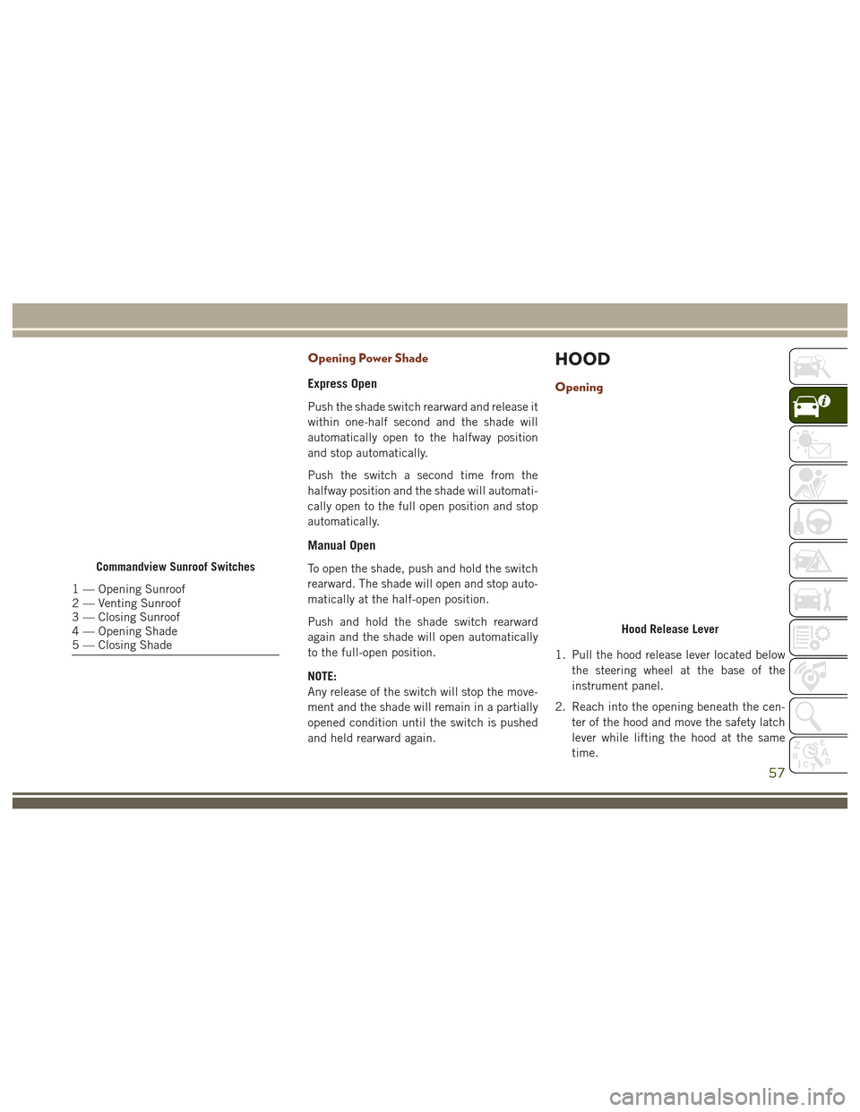
Commandview Sunroof Switches
1 — Opening Sunroof
2 — Venting Sunroof
3 — Closing Sunroof
4 — Opening Shade
5 — Closing Shade
Hood Release Lever
57
Page 76 of 372
INSTRUMENT CLUSTER
DISPLAY
Your vehicle may be equipped with an instru-
ment cluster display, which offers useful in-
formation to the driver. With the ignition in
the STOP/OFF position (and the key removed,
for vehicles with mechanical key), opening/
closing of a door will activate the display for
viewing, and display the total miles or kilo-
meters in the odometer. Your instrument
cluster display is designed to display impor-
tant information about your vehicle’s systems
and features. Using a driver interactive dis-
play located on the instrument panel, your
instrument cluster display can show you how
systems are working and give you warnings
when they aren’t. The steering wheel
mounted controls allow you to scroll through
and enter the main menus and submenus.
You can access the specific information you
want and make selections and adjustments.
Instrument Cluster Display Location and
Controls
The instrument cluster display is located in
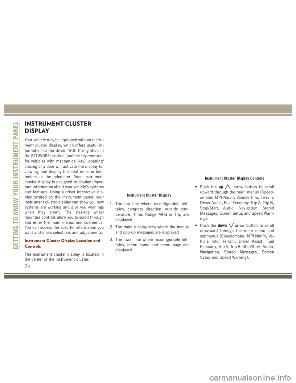
the center of the instrument cluster.1. The top line where reconfigurable tell-
tales, compass direction, outside tem-
perature, Time, Range MPG or Trip are
displayed
2. The main display area where the menus and pop up messages are displayed
3. The lower line where reconfigurable tell- tales, menu name and menu page are
displayed • Push the
up
arrow button to scroll
upward through the main menus (Speed-
ometer, MPH/km/h, Vehicle Info, Terrain,
Driver Assist, Fuel Economy, Trip A, Trip B,
Stop/Start, Audio, Navigation, Stored
Messages, Screen Setup and Speed Warn-
ing).
• Push the down
arrow button to scroll
downward through the main menu and
submenus (Speedometer, MPH/km/h, Ve-
hicle Info, Terrain, Driver Assist, Fuel
Economy, Trip A, Trip B, Stop/Start, Audio,
Navigation, Stored Messages, Screen
Setup and Speed Warning).
Instrument Cluster Display
Instrument Cluster Display Controls
GETTING TO KNOW YOUR INSTRUMENT PANEL
74
Page 84 of 372
– Oil Pressure Warning Light
This light indicates low engine oil pressure. If
the light turns on while driving, stop the
vehicle and shut off the engine as soon as
possible. A chime will sound when this light
turns on.
Do not operate the vehicle until the cause is
corrected. This light does not indicate how
much oil is in the engine. The engine oil level
must be checked under the hood.
– Engine Temperature Warning Light
This light warns of an overheated engine
condition. As engine coolant temperatures
rise and the gauge approachesH,this indica-
tor will illuminate and a single chime will
sound after reaching a set threshold.
If the light turns on while driving, safely pull
over and stop the vehicle. If the A/C system is
on, turn it off. Also, shift the transmission
into NEUTRAL and idle the vehicle. If the
temperature reading does not return to nor-
mal, turn the engine off immediately and call
for service. Refer to “If Your Engine Over-
heats” in “In Case Of Emergency” for further
information.
– Oil Temperature Warning Light
This telltale indicates engine oil temperature
is high. If the light turns on while driving,
stop the vehicle and shut off the engine as
soon as possible.
– Battery Charge Warning Light
This light illuminates when the battery is not
charging properly. If it stays on while the
engine is running, there may be a malfunc-
tion with the charging system. Contact your
authorized dealer as soon as possible. This
indicates a possible problem with the electri-
cal system or a related component.
If jump starting is required, refer to “Jump-
Starting” in “In Case Of Emergency.”
– Electronic Throttle Control (ETC)
Light
This light informs you of a problem with the
Electronic Throttle Control (ETC) system. If a
problem is detected while the engine is run-
ning, the light will either stay on or flash
depending on the nature of the problem.
Cycle the ignition key when the vehicle is
safely and completely stopped and the trans- mission is placed in the PARK position. The
light should turn off. If the light remains on
with the vehicle under power, your vehicle
will usually be drivable; however, see an au-
thorized dealer for service as soon as pos-
sible.
If the light continues to flash when the en-
gine vehicle under power, immediate service
is required and you may experience reduced
performance, and your vehicle may require
towing. The light will come on when the
ignition is placed in the ON/RUN position
and remain on briefly as a bulb check. If the
light does not come on during starting, have
the system checked by an authorized dealer.
– Electric Power Steering Fail Warn-
ing Light
This warning light indicates that there is a
fault in your vehicle’s Electric Power Steering
system.
GETTING TO KNOW YOUR INSTRUMENT PANEL
82
Page 85 of 372
NOTE:
• If the power steering assistance is no lon-ger operational, it is still possible to steer
the vehicle. Under these conditions there
will be a substantial increase in steering
effort, especially at low speeds and during
parking maneuvers.
• See your authorized dealer for service.
– Door Open Warning Light
This indicator will illuminate when a door is
ajar/open and not fully closed.
If the vehicle is moving, there will also be a
single chime.
– Liftgate Open Warning Light
This indicator will turn when the liftgate is
open.
If the vehicle is moving there will also be a
single chime.
– Transmission Temperature Warning
Light
This light indicates that there is excessive
transmission fluid temperature that might
occur with severe usage such as trailer tow- ing. If this light turns on, stop the vehicle and
run the engine at idle, with the transmission
in NEUTRAL, until the light turns off. Once
the light turns off, you may continue to drive
normally.
WARNING!
If you continue operating the vehicle when
the Transmission Temperature Warning
Light is illuminated you could cause the
fluid to boil over, come in contact with hot
engine or exhaust components and cause a
fire.
CAUTION!
Continuous driving with the Transmission
Temperature Warning Light illuminated
will eventually cause severe transmission
damage or transmission failure.
– Hood Open Warning Light
This indicator will illuminate when the hood
is left open and not fully closed.
Yellow Telltale Lights
– Engine Malfunction Warning Light
The Engine Check/Malfunction Indicator
Light (MIL) is a part of an Onboard Diagnostic
System called OBD II that monitors engine
and automatic transmission control systems.
The light will illuminate when the ignition is
in the ON position before engine start. If the
bulb does not come on when turning the key
from OFF to ON/RUN, have the condition
checked promptly.
Certain conditions, such as a loose or missing
gas cap, poor quality fuel, etc., may illumi-
nate the light after engine start. The vehicle
should be serviced if the light stays on
through several typical driving styles. In most
situations, the vehicle will drive normally and
will not require towing.
When the engine is running, the MIL may
flash to alert serious conditions that could
lead to immediate loss of power or severe
catalytic converter damage. The vehicle
should be serviced as soon as possible if this
occurs.
83
Page 86 of 372
WARNING!
A malfunctioning catalytic converter, as
referenced above, can reach higher tem-
peratures than in normal operating condi-
tions. This can cause a fire if you drive
slowly or park over flammable substances
such as dry plants, wood, cardboard, etc.
This could result in death or serious injury
to the driver, occupants or others.
CAUTION!
Prolonged driving with the Malfunction
Indicator Light (MIL) on could cause dam-
age to the engine control system. It also
could affect fuel economy and driveability.
If the MIL is flashing, severe catalytic
converter damage and power loss will soon
occur. Immediate service is required.
– Electronic Stability Control (ESC)
Warning Light
The “ESC Indicator Light” in the instrument
cluster will come on when the ignition switch
is turned to the ON/RUN position. It should
go out when the engine is running. If the “ESC Indicator Light” comes on continuously
with the engine running, a malfunction has
been detected in the ESC system. If this light
remains on after several ignition cycles, and
the vehicle has been driven several miles
(kilometers) at speeds greater than 30 mph
(48 km/h), see your authorized dealer as soon
as possible to have the problem diagnosed
and corrected.
• The “ESC Off Indicator Light” and the
“ESC Indicator Light” come on momen-
tarily each time the ignition switch is
turned to ON/RUN.
• Each time the ignition is turned to ON/ RUN, the ESC system will be ON, even if it
was turned off previously.
• The ESC system will make buzzing or clicking sounds when it is active. This is
normal; the sounds will stop when ESC
becomes inactive following the maneuver
that caused the ESC activation.
This telltale indicates that an ESC event is
active.
– Electronic Stability Control (ESC) OFF
Indicator Light — If Equipped
This light indicates the Electronic Stability
Control (ESC) is off.
– Tire Pressure Monitoring System
(TPMS) Warning Light
The warning light switches on and a message
is displayed to indicate that the tire pressure
is lower than the recommended value and/or
that slow pressure loss is occurring. In these
cases, optimal tire duration and fuel con-
sumption may not be guaranteed.
Should one or more tires be in the condition
mentioned above, the display will show the
indications corresponding to each tire in se-
quence.
IMPORTANT: Do not continue driving with one
or more flat tires as handling may be compro-
mised. Stop the vehicle, avoiding sharp brak-
ing and steering. Repair immediately using
the dedicated tire repair kit and contact your
authorized dealer as soon as possible.
GETTING TO KNOW YOUR INSTRUMENT PANEL
84
Page 90 of 372
– Cruise Control Set Indicator Light
This light will turn on when the electronic
speed control is SET. Refer to “Electronic
Speed Control — If Equipped” in “Starting
And Operating” for further information.
— Adaptive Cruise Control (ACC) Set
With No Target Detected Light — If
Equipped
This light will turn on when the Adaptive
Cruise Control is SET and there is no target
vehicle detected. Refer to "Adaptive Cruise
Control (ACC) — If Equipped" in "Starting
And Operating" for further information.
— Adaptive Cruise Control (ACC) Set
With Target Detected Light — If Equipped
This light will turn on when the Adaptive
Cruise Control is SET and the target vehicle is
detected. Refer to "Adaptive Cruise Control
(ACC) — If Equipped" in "Starting And Oper-
ating" for further information.
— LaneSense Indicator Light — If
Equipped
The LaneSense indicator is solid green when
both lane markings have been detected and
the system is “armed” to provide visual warn-
ings in the instrument cluster display and a
torque warning in the steering wheel if an
unintentional lane departure occurs. Refer to
“LaneSense — If Equipped" in “Starting And
Operating” for further information.
White Telltale Lights
— Cruise Control Ready Indicator
Light
This light will turn on when the electronic
speed control is ready, but not set.
— Adaptive Cruise Control (ACC) Ready
Light — If Equipped
This light will turn on when the vehicle
equipped with Adaptive Cruise Control (ACC)
has been turned on and in the READY state.
Refer to “Adaptive Cruise Control (ACC) — If
Equipped” in “Starting And Operating” for
further information.
— Selec Speed Control Indicator
Light — If Equipped
This light will turn on when “Selec Speed
Control” is activated.
To activate “Selec Speed Control”, assure the
vehicle is Four Wheel Drive Low (4WD) and
push the button on the Instrument Panel.
NOTE:
If the vehicle is not in 4WD Low, “To Enter
Selec-Speed Shift to 4WD Low” will appear
in the instrument cluster display.
— LaneSense Indicator Light — If
Equipped
When the LaneSense system is ON, the La-
neSense indicator is solid white when none or
only the left or right lane marking has been
detected. The indicator will turn green when
both lanes are detected and the system will
be ready to provide visual warnings in the
instrument cluster display if an unintentional
lane departure occurs. Refer to “LaneSense
— If Equipped" in “Starting And Operating”
for further information.
GETTING TO KNOW YOUR INSTRUMENT PANEL
88
Page 94 of 372
SAFETY FEATURES
Anti-Lock Brake System (ABS)
The Anti-Lock Brake System (ABS) provides
increased vehicle stability and brake perfor-
mance under most braking conditions. The
system automatically prevents wheel lock,
and enhances vehicle control during braking.
The ABS performs a self-check cycle to en-
sure that the ABS is working properly each
time the vehicle is started and driven. During
this self-check, you may hear a slight clicking
sound as well as some related motor noises.
ABS is activated during braking when the
system detects one or more wheels begin to
lock. Road conditions such as ice, snow,
gravel, bumps, railroad tracks, loose debris,
or panic stops may increase the likelihood of
ABS activation(s).
You also may experience the following when
ABS activates:
• The ABS motor noise (it may continue torun for a short time after the stop).
• The clicking sound of solenoid valves.
• Brake pedal pulsations. • A slight drop of the brake pedal at the end
of the stop.
These are all normal characteristics of ABS.
WARNING!
• The ABS contains sophisticated elec- tronic equipment that may be suscep-
tible to interference caused by improp-
erly installed or high output radio
transmitting equipment. This interfer-
ence can cause possible loss of anti-lock
braking capability. Installation of such
equipment should be performed by
qualified professionals.
• Pumping of the Anti-Lock Brakes will
diminish their effectiveness and may
lead to a collision. Pumping makes the
stopping distance longer. Just press
firmly on your brake pedal when you
need to slow down or stop.
• The ABS cannot prevent the natural laws
of physics from acting on the vehicle,
nor can it increase braking or steering
efficiency beyond that afforded by the
WARNING!
condition of the vehicle brakes and tires
or the traction afforded.
• The ABS cannot prevent collisions, in-
cluding those resulting from excessive
speed in turns, following another vehicle
too closely, or hydroplaning.
• The capabilities of an ABS equipped
vehicle must never be exploited in a
reckless or dangerous manner that could
jeopardize the user’s safety or the safety
of others.
ABS is designed to function with the OEM
tires. Modification may result in degraded
ABS performance.
Anti-Lock Brake Warning Light
The yellow “Anti-Lock Brake Warning Light”
will turn on when the ignition is turned to the
ON/RUN mode and may stay on for as long as
four seconds.
If the “Anti-Lock Brake Warning Light” re-
mains on or comes on while driving, it indi-
cates that the anti-lock portion of the brake
system is not functioning and that service is
SAFETY
92
Page 95 of 372
required. However, the conventional brake
system will continue to operate normally if
the “Brake System Warning Light” is not on.
If the “Anti-Lock Brake Warning Light” is on,
the brake system should be serviced as soon
as possible to restore the benefits of anti-lock
brakes. If the “Anti-Lock Brake Warning
Light” does not come on when the ignition is
turned to the ON/RUN mode, have the light
repaired as soon as possible.
Electronic Brake Control System
Your vehicle is equipped with an advanced
Electronic Brake Control system (EBC). This
system includes Electronic Brake Force Dis-
tribution (EBD), Anti-Lock Brake System
(ABS), Brake Assist System (BAS), Hill Start
Assist (HSA), Traction Control System (TCS),
Electronic Stability Control (ESC), and Elec-
tronic Roll Mitigation (ERM). These systems
work together to enhance both vehicle stabil-
ity and control in various driving conditions.Your vehicle may also be equipped with
Trailer Sway Control (TSC), Ready Alert Brak-
ing (RAB), Rain Brake Support (RBS), Dy-
namic Steering Torque (DST), Hill Descent
Control (HDC), and Selec-Speed Control
(SSC).
Electronic Brake Force Distribution (EBD)
This function manages the distribution of the
braking torque between the front and rear
axles by limiting braking pressure to the rear
axle. This is done to prevent overslip of the
rear wheels to avoid vehicle instability, and to
prevent the rear axle from entering ABS be-
fore the front axle.
Brake System Warning Light
The red “Brake System Warning Light” will
turn on when the ignition is turned to the
ON/RUN mode and may stay on for as long as
four seconds.
If the “Brake System Warning Light” remains
on or comes on while driving, it indicates that
the brake system is not functioning properly
and that immediate service is required. If the“Brake System Warning Light” does not
come on when the ignition is turned to the
ON/RUN mode, have the light repaired as
soon as possible.
Brake Assist System (BAS)
The BAS is designed to optimize the vehicle’s
braking capability during emergency braking
maneuvers. The system detects an emer-
gency braking situation by sensing the rate
and amount of brake application and then
applies optimum pressure to the brakes. This
can help reduce braking distances. The BAS
complements the anti-lock brake system
(ABS). Applying the brakes very quickly re-
sults in the best BAS assistance. To receive
the benefit of the system, you must apply
continuous braking pressure during the stop-
ping sequence, (do not “pump” the brakes).
Do not reduce brake pedal pressure unless
braking is no longer desired. Once the brake
pedal is released, the BAS is deactivated.
93
Page 97 of 372
For vehicles not equipped with an instrument
cluster display, perform the following steps:
1. Center the steering wheel (front wheelspointing straight forward).
2. Shift the transmission into PARK.
3. Apply the parking brake.
4. Start the engine.
5. Rotate the steering wheel slightly more than one-half turn to the left.
6. Push the “ESC Off” button located in the lower switch bank below the climate con-
trol four times within twenty seconds. The
“ESC Off Indicator Light” should turn on
and turn off two times.
7. Rotate the steering wheel back to center and then an additional slighty more than
one-half turn to the right.
8. Turn the ignition to the OFF mode and then back to ON. If the sequence was
completed properly, the “ESC Off Indica-
tor Light” will blink several times to con-
firm HSA is disabled.
9. Repeat these steps if you want to return this feature to its previous setting.Towing With HSA
HSA will also provide assistance to mitigate
roll back while towing a trailer.
WARNING!
• If you use a trailer brake controller withyour trailer, the trailer brakes may be
activated and deactivated with the brake
switch. If so, there may not be enough
brake pressure to hold both the vehicle
and the trailer on a hill when the brake
pedal is released. In order to avoid roll-
ing down an incline while resuming ac-
celeration, manually activate the trailer
brake or apply more vehicle brake pres-
sure prior to releasing the brake pedal.
• HSA is not a parking brake. Always apply
the parking brake fully when leaving your
vehicle. Also, be certain to leave the
transmission in PARK.
• Failure to follow these warnings can re-
sult in a collision or serious personal
injury.
Traction Control System (TCS)
This system monitors the amount of wheel
spin of each of the driven wheels. If wheel
spin is detected, the TCS may apply brake
pressure to the spinning wheel(s) and/or re-
duce engine power to provide enhanced ac-
celeration and stability. A feature of the TCS,
Brake Limited Differential (BLD), functions
similar to a limited slip differential and con-
trols the wheel spin across a driven axle. If
one wheel on a driven axle is spinning faster
than the other, the system will apply the
brake of the spinning wheel. This will allow
more engine torque to be applied to the wheel
that is not spinning. BLD may remain en-
abled even if TCS and ESC are in a reduced
mode.
Electronic Stability Control (ESC)
This system enhances directional control and
stability of the vehicle under various driving
conditions. ESC corrects for oversteering or
understeering of the vehicle by applying the
brake of the appropriate wheel(s) to assist in
counteracting the oversteer or understeer
condition. Engine power may also be reduced
to help the vehicle maintain the desired path.
95