steering JEEP GRAND CHEROKEE 2017 WK2 / 4.G Service Manual
[x] Cancel search | Manufacturer: JEEP, Model Year: 2017, Model line: GRAND CHEROKEE, Model: JEEP GRAND CHEROKEE 2017 WK2 / 4.GPages: 372
Page 186 of 372
Turning LaneSense ON Or OFF
The default status of LaneSense is “OFF”.
The LaneSense button is located on the
switch panel below the Uconnect display.
To turn the LaneSense system ON, push the
LaneSense button to turn the system ON
(LED turns off). A “Lane Sense On” message
is shown in the instrument cluster display.
To turn the LaneSense system OFF, push the
LaneSense button once to turn the system
OFF (LED turns on).
NOTE:
The LaneSense system will retain the last
system state ON or OFF from the last ignition
cycle when the ignition is changed to the
ON/RUN position.
LaneSense Warning Message
The LaneSense system will indicate the cur-
rent lane drift condition through the instru-
ment cluster display.7.0 Instrument Cluster Display
When the LaneSense system is ON; the lane
lines are gray when both of the lane bound-
aries have not been detected and the La-
neSense indicator is solid white.
Left Lane Departure — Only Left Lane Detected
• When the LaneSense system is ON, the
LaneSense indicator is solid white when
only the left lane marking has been de-
tected and the system is ready to provide
visual warnings in the instrument cluster
display if an unintentional lane departure
occurs.
• When the LaneSense system senses the lane has been approached and is in a lane
departure situation, the left thick lane line
flashes yellow (on/off), the left thin line
remains solid yellow and the LaneSense
indicator changes from solid white to
flashing yellow.
NOTE:
The LaneSense system operates with the
similar behavior for a right lane departure
when only the right lane marking has been
detected. Left Lane Departure — Both Lanes Detected
• When the LaneSense system is ON, the
lane lines turn from gray to white to indi-
cate that both of the lane markings have
been detected. The LaneSense indicator
is solid green when both lane markings
have been detected and the system is ON
to provide visual warnings in the instru-
ment cluster display and a torque warning
in the steering wheel if an unintentional
lane departure occurs.
• When the LaneSense system senses a lane drift situation, the left thick lane line and
left thin line turn solid yellow. The La-
neSense indicator changes from solid
green to solid yellow. At this time torque is
applied to the steering wheel in the oppo-
site direction of the lane boundary.
For example: If approaching the left side of
the lane the steering wheel will turn to the
right.
• When the LaneSense system senses the lane has been approached and is in a lane
departure situation, the left thick lane line
flashes yellow (on/off) and the left thin
line remains solid yellow. The LaneSense
indicator changes from solid yellow to
STARTING AND OPERATING
184
Page 187 of 372
flashing yellow. At this time torque is ap-
plied to the steering wheel in the opposite
direction of the lane boundary.
For example: If approaching the left side of
the lane the steering wheel will turn to the
right.
NOTE:
The LaneSense system operates with the
similar behavior for a right lane departure.
Changing LaneSense Status
The LaneSense system has settings to adjust
the intensity of the torque warning and the
warning zone sensitivity (early/late) that you
can configure through the Uconnect system
screen. Refer to “Uconnect Settings” in
“Multimedia” for further information.
NOTE:
• When enabled the system operates above 37 mph (60 km/h) and below 112 mph
(180 km/h).
• Use of the turn signal suppresses the warnings. • The system will not apply torque to the
steering wheel whenever a safety system
engages. (anti-lock brakes, traction con-
trol system, electronic stability control,
forward collision warning, etc.).
PARKVIEW REAR BACK-UP
CAMERA
Symbols And Messages On The Display
You can see an on-screen image of the rear of
your vehicle whenever the transmission is
shifted into REVERSE. The ParkView Rear
Back-Up Camera image will be displayed on
the Uconnect Display, located on the center
stack of the instrument panel.
If the Uconnect Display appears foggy, clean
the camera lens located on the rear of the
vehicle above the rear license plate.
Rear Camera — Viewing At Speed
When the vehicle is in PARK, NEUTRAL or
DRIVE, the Rear View Camera can be acti-
vated with the “Rear View Camera” button in
the Controls menu. This feature allows the
customer to monitor the area directly behind the vehicle (or trailer, if equipped) for up to
ten seconds while at speed. If the vehicle
speed remains below 8 mph (13 km/h), the
Rear View Camera image will be displayed
continuously until deactivated via the “X”
button on the touchscreen.
Refer to “ParkView Rear Back-Up Camera —
If Equipped” in “Starting And Operating” in
your Owner's Manual at
www.jeep.com/en/owners/manuals/ for fur-
ther details.
WARNING!
Drivers must be careful when backing up;
even when using the ParkView Rear
Back-Up Camera. Always check carefully
behind your vehicle, and be sure to check
for pedestrians, animals, other vehicles,
obstructions, or blind spots before backing
up. You must continue to pay attention
while backing up. Failure to do so can
result in serious injury or death.
185
Page 211 of 372
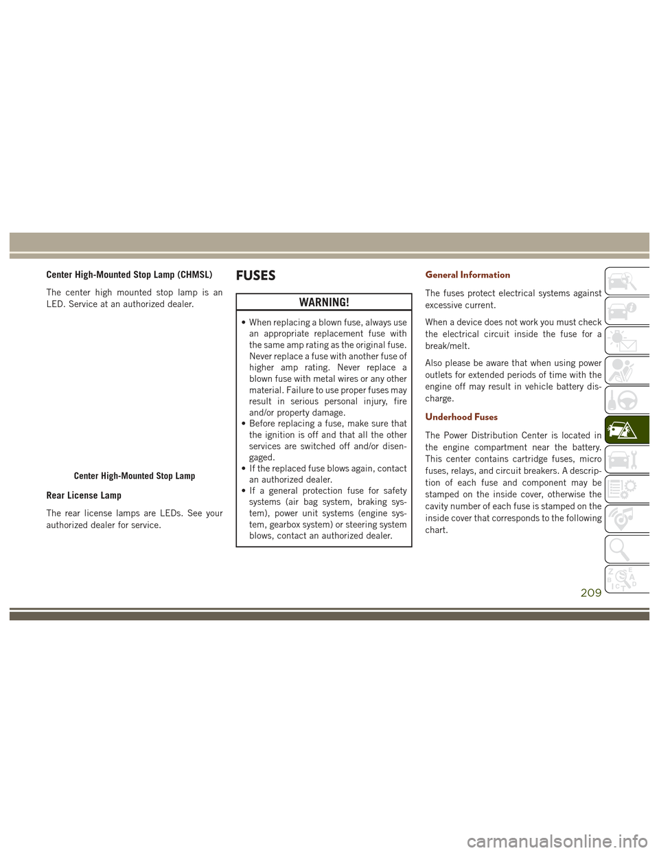
Center High-Mounted Stop Lamp (CHMSL)
The center high mounted stop lamp is an
LED. Service at an authorized dealer.
Rear License Lamp
The rear license lamps are LEDs. See your
authorized dealer for service.
FUSES
WARNING!
• When replacing a blown fuse, always usean appropriate replacement fuse with
the same amp rating as the original fuse.
Never replace a fuse with another fuse of
higher amp rating. Never replace a
blown fuse with metal wires or any other
material. Failure to use proper fuses may
result in serious personal injury, fire
and/or property damage.
• Before replacing a fuse, make sure that
the ignition is off and that all the other
services are switched off and/or disen-
gaged.
• If the replaced fuse blows again, contact
an authorized dealer.
• If a general protection fuse for safety
systems (air bag system, braking sys-
tem), power unit systems (engine sys-
tem, gearbox system) or steering system
blows, contact an authorized dealer.
General Information
The fuses protect electrical systems against
excessive current.
When a device does not work you must check
the electrical circuit inside the fuse for a
break/melt.
Also please be aware that when using power
outlets for extended periods of time with the
engine off may result in vehicle battery dis-
charge.
Underhood Fuses
The Power Distribution Center is located in
the engine compartment near the battery.
This center contains cartridge fuses, micro
fuses, relays, and circuit breakers. A descrip-
tion of each fuse and component may be
stamped on the inside cover, otherwise the
cavity number of each fuse is stamped on the
inside cover that corresponds to the following
chart.
Center High-Mounted Stop Lamp
209
Page 214 of 372
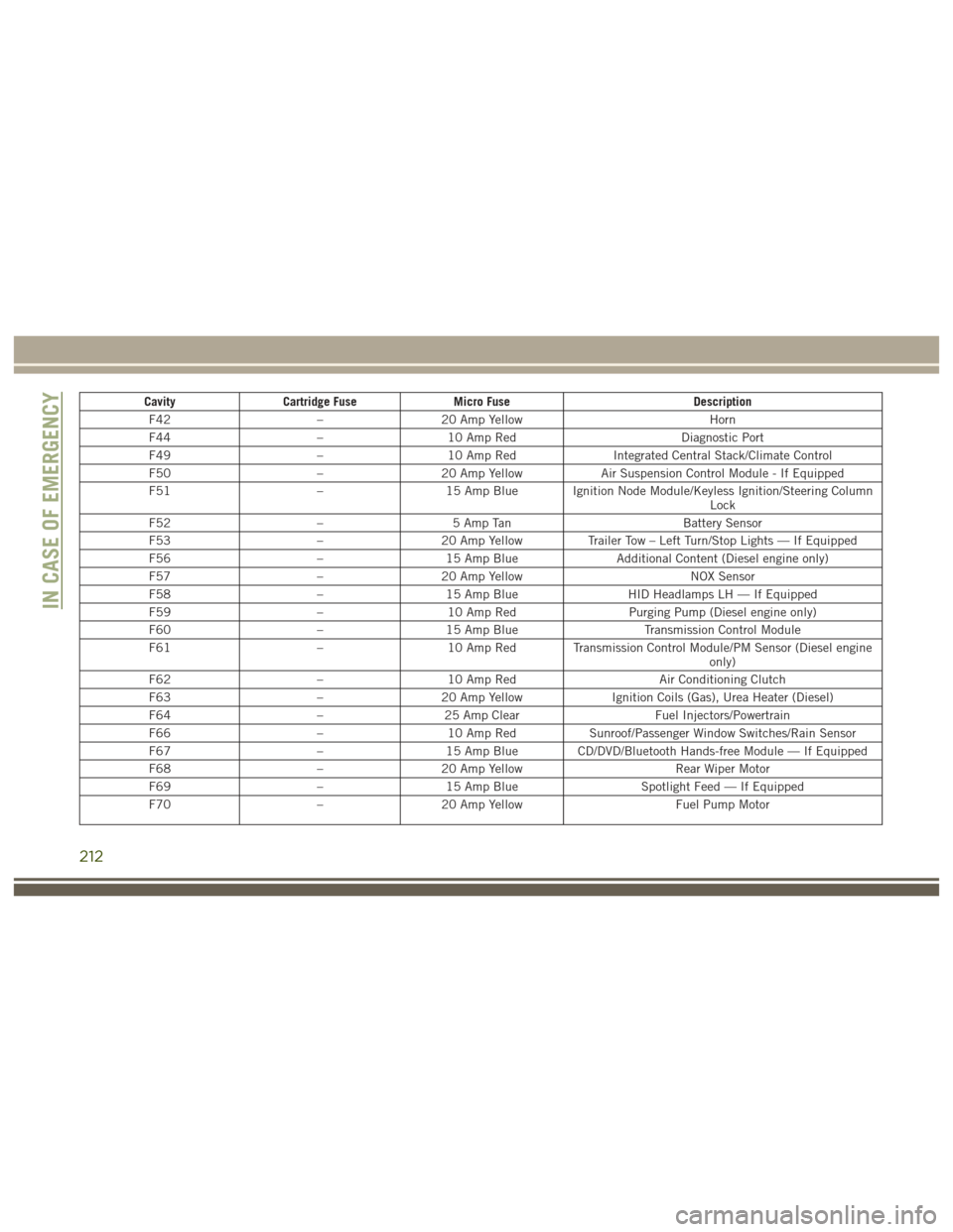
CavityCartridge Fuse Micro Fuse Description
F42 –20 Amp Yellow Horn
F44 –10 Amp Red Diagnostic Port
F49 –10 Amp Red Integrated Central Stack/Climate Control
F50 –20 Amp Yellow Air Suspension Control Module - If Equipped
F51 –15 Amp Blue Ignition Node Module/Keyless Ignition/Steering Column
Lock
F52 –5 Amp Tan Battery Sensor
F53 –20 Amp Yellow Trailer Tow – Left Turn/Stop Lights — If Equipped
F56 –15 Amp Blue Additional Content (Diesel engine only)
F57 –20 Amp Yellow NOX Sensor
F58 –15 Amp Blue HID Headlamps LH — If Equipped
F59 –10 Amp Red Purging Pump (Diesel engine only)
F60 –15 Amp Blue Transmission Control Module
F61 –10 Amp Red Transmission Control Module/PM Sensor (Diesel engine
only)
F62 –10 Amp Red Air Conditioning Clutch
F63 –20 Amp Yellow Ignition Coils (Gas), Urea Heater (Diesel)
F64 –25 Amp Clear Fuel Injectors/Powertrain
F66 –10 Amp Red Sunroof/Passenger Window Switches/Rain Sensor
F67 –15 Amp Blue CD/DVD/Bluetooth Hands-free Module — If Equipped
F68 –20 Amp Yellow Rear Wiper Motor
F69 –15 Amp Blue Spotlight Feed — If Equipped
F70 –20 Amp Yellow Fuel Pump Motor
IN CASE OF EMERGENCY
212
Page 215 of 372
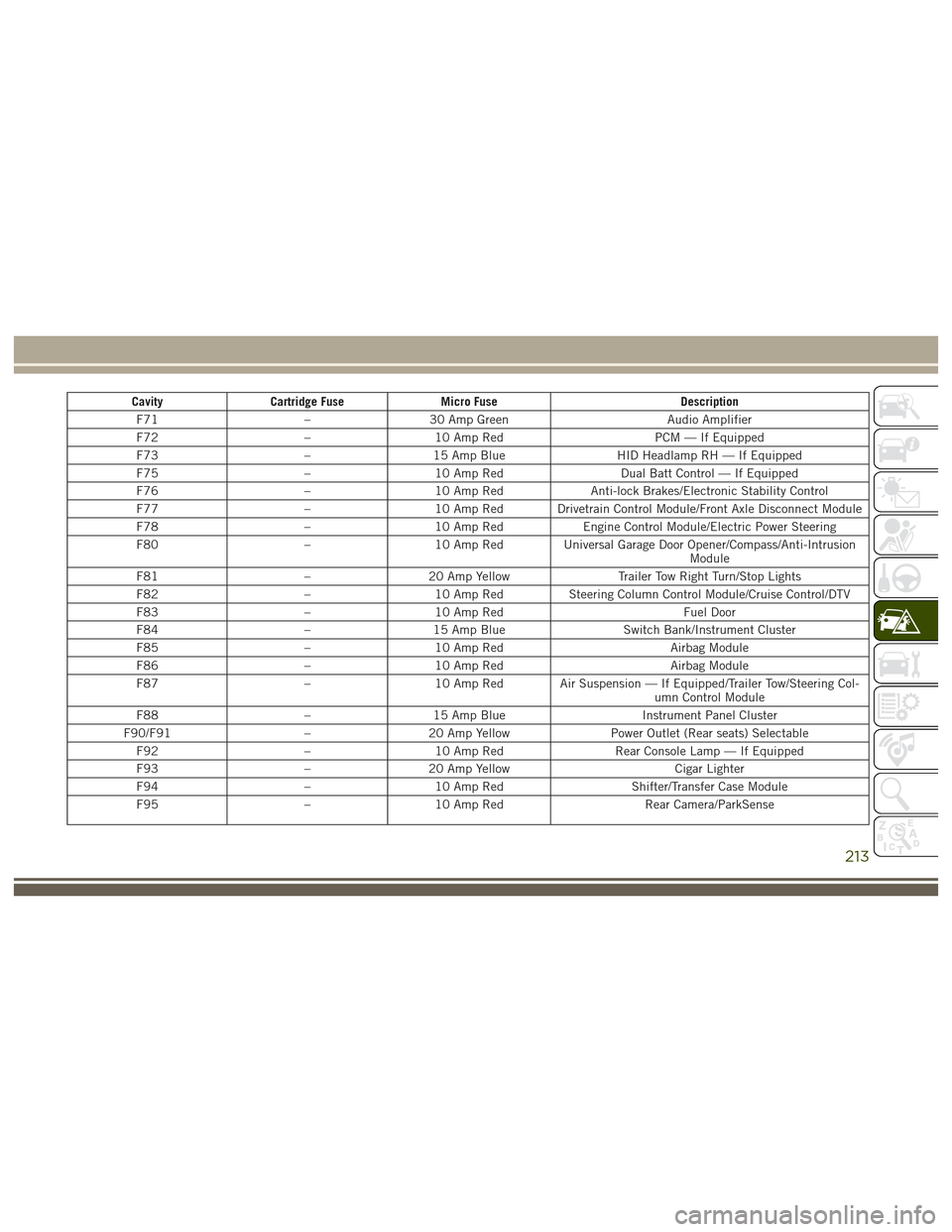
CavityCartridge Fuse Micro Fuse Description
F71 –30 Amp Green Audio Amplifier
F72 –10 Amp Red PCM — If Equipped
F73 –15 Amp Blue HID Headlamp RH — If Equipped
F75 –10 Amp Red Dual Batt Control — If Equipped
F76 –10 Amp Red Anti-lock Brakes/Electronic Stability Control
F77 –10 Amp Red Drivetrain Control Module/Front Axle Disconnect Module
F78 –10 Amp Red Engine Control Module/Electric Power Steering
F80 –10 Amp Red Universal Garage Door Opener/Compass/Anti-Intrusion
Module
F81 –20 Amp Yellow Trailer Tow Right Turn/Stop Lights
F82 –10 Amp Red Steering Column Control Module/Cruise Control/DTV
F83 –10 Amp Red Fuel Door
F84 –15 Amp Blue Switch Bank/Instrument Cluster
F85 –10 Amp Red Airbag Module
F86 –10 Amp Red Airbag Module
F87 –10 Amp Red Air Suspension — If Equipped/Trailer Tow/Steering Col-
umn Control Module
F88 –15 Amp Blue Instrument Panel Cluster
F90/F91 –20 Amp Yellow Power Outlet (Rear seats) Selectable
F92 –10 Amp Red Rear Console Lamp — If Equipped
F93 –20 Amp Yellow Cigar Lighter
F94 –10 Amp Red Shifter/Transfer Case Module
F95 –10 Amp Red Rear Camera/ParkSense
213
Page 216 of 372
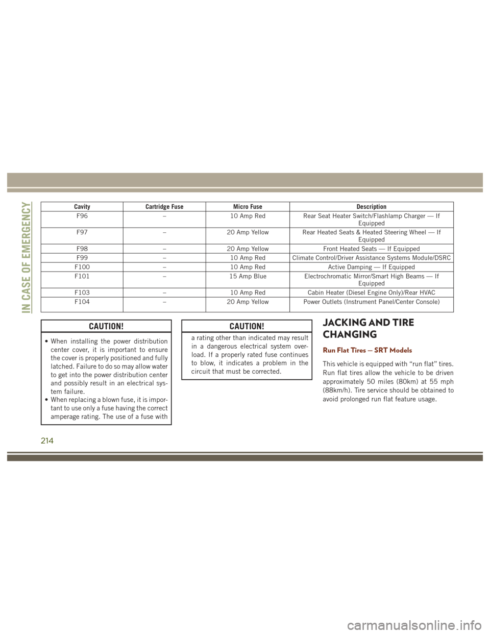
CavityCartridge Fuse Micro Fuse Description
F96 –10 Amp Red Rear Seat Heater Switch/Flashlamp Charger — If
Equipped
F97 –20 Amp Yellow Rear Heated Seats & Heated Steering Wheel — If
Equipped
F98 –20 Amp Yellow Front Heated Seats — If Equipped
F99 –10 Amp Red Climate Control/Driver Assistance Systems Module/DSRC
F100 –10 Amp Red Active Damping — If Equipped
F101 –15 Amp Blue Electrochromatic Mirror/Smart High Beams — If
Equipped
F103 –10 Amp Red Cabin Heater (Diesel Engine Only)/Rear HVAC
F104 –20 Amp Yellow Power Outlets (Instrument Panel/Center Console)
CAUTION!
• When installing the power distribution
center cover, it is important to ensure
the cover is properly positioned and fully
latched. Failure to do so may allow water
to get into the power distribution center
and possibly result in an electrical sys-
tem failure.
• When replacing a blown fuse, it is impor-
tant to use only a fuse having the correct
amperage rating. The use of a fuse with
CAUTION!
a rating other than indicated may result
in a dangerous electrical system over-
load. If a properly rated fuse continues
to blow, it indicates a problem in the
circuit that must be corrected.
JACKING AND TIRE
CHANGING
Run Flat Tires — SRT Models
This vehicle is equipped with “run flat” tires.
Run flat tires allow the vehicle to be driven
approximately 50 miles (80km) at 55 mph
(88km/h). Tire service should be obtained to
avoid prolonged run flat feature usage.
IN CASE OF EMERGENCY
214
Page 228 of 372
FREEING A STUCK VEHICLE
If your vehicle becomes stuck in mud, sand
or snow, it can often be moved using a rock-
ing motion. Turn the steering wheel right and
left to clear the area around the front wheels.
Push and hold the lock button on the gear
selector. Then shift back and forth between
DRIVE and REVERSE while gently pressing
the accelerator.
NOTE:
Shifts between DRIVE and REVERSE can
only be achieved at wheel speeds of 5 mph
(8 km/h) or less. Whenever the transmission
remains in NEUTRAL for more than two sec-
onds, you must press the brake pedal to
engage DRIVE or REVERSE.
Use the least amount of accelerator pedal
pressure that will maintain the rocking mo-
tion without spinning the wheels or racing the
engine.NOTE:
Push the "ESC Off" switch (if necessary), to
place the Electronic Stability Control (ESC)
system in "Partial Off" mode, before rocking
the vehicle. Refer to “Electronic Brake Con-
trol” in “Safety” in the Owners Manual at
www.jeep.com/en/owners/manuals/ for fur-
ther information. Once the vehicle has been
freed, push the "ESC Off" switch again to
restore "ESC On" mode.
WARNING!
Fast spinning tires can be dangerous.
Forces generated by excessive wheel
speeds may cause damage, or even failure,
of the axle and tires. A tire could explode
and injure someone. Do not spin your
vehicle's wheels faster than 30 mph
(48 km/h) or for longer than 30 seconds
continuously without stopping when you
are stuck and do not let anyone near a
spinning wheel, no matter what the speed.
CAUTION!
• Racing the engine or spinning the
wheels may lead to transmission over-
heating and failure. Allow the engine to
idle with the transmission in NEUTRAL
for at least one minute after every five
rocking-motion cycles. This will mini-
mize overheating and reduce the risk of
transmission failure during prolonged
efforts to free a stuck vehicle.
• When “rocking” a stuck vehicle by shift-
ing between DRIVE and REVERSE, do
not spin the wheels faster than 15 mph
(24 km/h), or drivetrain damage may
result.
• Revving the engine or spinning the
wheels too fast may lead to transmission
overheating and failure. It can also dam-
age the tires. Do not spin the wheels
above 30 mph (48 km/h) while in gear
(no transmission shifting occurring).
IN CASE OF EMERGENCY
226
Page 230 of 372
NOTE:
SRT vehicles and 4WD models without 4WD
LOW range should only be towed with all four
wheelsOFFthe ground.
Proper towing or lifting equipment is required
to prevent damage to your vehicle. Use only
tow bars and other equipment designed for
this purpose, following equipment manufac-
turer’s instructions. Use of safety chains is
mandatory. Attach a tow bar or other towing
device to main structural members of the
vehicle, not to bumpers or associated brack-
ets. State and local laws regarding vehicles
under tow must be observed.
If you must use the accessories (wipers, de-
frosters, etc.) while being towed, the ignition
must be in the ON/RUN mode, not the ACC
mode.
If the key fob is unavailable, or the vehicle's
battery is discharged, refer to “Manual Park
Release” in this section for instructions on
shifting the transmission out of PARK for
towing.CAUTION!
• Do not use sling type equipment when towing. Vehicle damage may occur.
• When securing the vehicle to a flat bed
truck, do not attach to front or rear
suspension components. Damage to
your vehicle may result from improper
towing.
Two-Wheel Drive Models
The manufacturer recommends towing your
vehicle with all four wheels OFFthe ground
using a flatbed.
If flatbed equipment is not available, and the
transmission is operable, the vehicle may be
towed (with rear wheels on the ground) under
the following conditions:
• The transmission must be in NEUTRAL. Refer to "Manual Park Release" in this
section for instructions on shifting the
transmission to NEUTRAL when the en-
gine is off.
• The towing speed must not exceed 30 mph (48 km/h). • The towing distance must not exceed
30 miles (48 km).
If the transmission is not operable, or the
vehicle must be towed faster than 30 mph
(48 km/h) or farther than 30 miles (48 km),
tow with the rear wheels OFFthe ground.
Acceptable methods are to tow the vehicle on
a flatbed, or with the front wheels raised and
the rear wheels on a towing dolly, or (when
using a suitable steering wheel stabilizer to
hold the front wheels in the straight position)
with the rear wheels raised and the front
wheels on the ground.
CAUTION!
Towing faster than 30 mph (48 km/h) or
farther than 30 miles (48 km) with rear
wheels on the ground can cause severe
transmission damage. Damage from im-
proper towing is not covered under the
New Vehicle Limited Warranty.
IN CASE OF EMERGENCY
228
Page 267 of 372
Dark Vapor Or Black Satin Chrome Wheels
CAUTION!
If your vehicle is equipped with Dark Vapor
or Black Satin Chrome wheels DO NOT
USE wheel cleaners, abrasives or polishing
compounds. They will permanently dam-
age this finish and such damage is not
covered by the New Vehicle Limited War-
ranty. USE ONLY MILD SOAP AND WATER
WITH A SOFT CLOTH. Used on a regular
basis this is all that is required to maintain
this finish.
Tire Chains (Traction Devices)
Use of traction devices require sufficient tire-
to-body clearance. Follow these recommen-
dations to guard against damage.
• Traction device must be of proper size forthe tire, as recommended by the traction
device manufacturer.
• Install on Rear Tires Only • Due to limited clearance, Thule XG-12 Pro
or equivalent is recommended on P245/
70/R17, P265/60R18 or
265/50R20 tires.
WARNING!
Using tires of different size and type (M+S,
Snow) between front and rear axles can
cause unpredictable handling. You could
lose control and have a collision.
CAUTION!
To avoid damage to your vehicle or tires,
observe the following precautions:
• Because of restricted traction deviceclearance between tires and other sus-
pension components, it is important that
only traction devices in good condition
are used. Broken devices can cause se-
rious damage. Stop the vehicle immedi-
ately if noise occurs that could indicate
device breakage. Remove the damaged
parts of the device before further use.
CAUTION!
• Install device as tightly as possible andthen retighten after driving about ½ mile
(0.8 km).
• Do not exceed 30 mph (48 km/h).
• Drive cautiously and avoid severe turns
and large bumps, especially with a
loaded vehicle.
• Do not drive for a prolonged period on
dry pavement.
• Observe the traction device manufactur-
er’s instructions on the method of instal-
lation, operating speed, and conditions
for use. Always use the suggested oper-
ating speed of the device manufacturer’s
if it is less than 30 mph (48 km/h).
• Do not use traction devices on a com-
pact spare tire.
Tire Rotation Recommendations
The tires on the front and rear of your vehicle
operate at different loads and perform differ-
ent steering, handling, and braking func-
tions. For these reasons, they wear at unequal
rates.
265
Page 287 of 372
MULTIMEDIA
CYBERSECURITY............287
OFFROADPAGES—IF
EQUIPPED................ .288
Off Road Pages Status Bar........288
Drivetrain ...................288
Suspension ..................289
Accessory Gauges ..............289
Selec-Terrain .................289
TIPS CONTROLS AND GENERAL
INFORMATION ............ .290
Steering Wheel Audio Controls ......290
Reception Conditions ............290
Care And Maintenance ...........290
Anti-theft Protection ............291
UCONNECT ACCESS .........291
Uconnect Access — If Equipped (Available
On Uconnect 8.4/8.4 NAV — U.S.
Residents Only)...............291
Uconnect Access Registration (Uconnect
8.4/8.4 NAV, U.S. 48 Contiguous States,
Alaska And Hawaii) ............293
Download The Uconnect Access App . .293 Via Mobile Apps — If Equipped
.....294
Vehicle Finder ................295
Send&Go ..................296
Renewing Subscriptions And
Purchasing 3G Wi-Fi Hotspot (Uconnect
8.4/8.4 NAV, U.S. 48 Contiguous States,
Alaska And Hawaii) .............296
Getting Started With Apps ........297
Maintaining Your Uconnect Access
Account ....................298
Built-In Features ..............298
Vehicle Health Report/Alert ........301
Uconnect Access Remote Features . . .301
UCONNECT 5.0 .............305
Controls On The Front Panel .......305
Clock Setting .................306
Equalizer, Balance And Fade .......306
Radio Mode ..................307
Media Mode .................307
Bluetooth Source ..............310
iPod/USB/SD Card/AUX/Media Player
Control Support ...............311 USB/Audio Jack (AUX)/Bluetooth
Operation
...................311
Phone Mode .................312
SiriusXM Premier Over 160 Channels . .315
UCONNECT 8.4/8.4 NAV ......316
Uconnect 8.4/8.4 NAV At A Glance . . .316
Personalized Menu Bar...........318
Radio Mode ..................318
SiriusXM Premier Over 160 Channels .319
UCONNECT TOUCH SETTINGS . .322
IPOD/USB/SD CARD/MEDIA
PLAYERCONTROL ..........322
Audio Jack (AUX) ..............323
USB Port ...................323
SD Card ....................323
Bluetooth Streaming Audio ........323
Media Controls ................324
UCONNECT REAR SEAT ENTER-
TAINMENT (RSE) SYSTEM — IF
EQUIPPED................ .324
Getting Started...............324
MULTIMEDIA
285