ECO mode JEEP GRAND CHEROKEE 2017 WK2 / 4.G Owner's Manual
[x] Cancel search | Manufacturer: JEEP, Model Year: 2017, Model line: GRAND CHEROKEE, Model: JEEP GRAND CHEROKEE 2017 WK2 / 4.GPages: 372
Page 109 of 372
Tire Pressure Monitor System (TPMS)
NOTE:
For vehicles equipped with run flat tires —
When the TPMS indicates a tire pressure of
14 psi (96 kPa) or lower, always check tire
pressure and replace the tire at the first
opportunity. At inflation pressure of/or below
14 psi (96 kPa) the tire is in the run-flat
mode of operation. In this condition, it is
recommended a vehicle maximum speed of
50 mph (80 km/h) for a maximum distance of
50 miles (80 km). The manufacturer does not
recommend using the run flat feature while
driving a vehicle loaded at full capacity or
towing a trailer.
The Tire Pressure Monitoring System (TPMS)
will warn the driver of a low tire pressure
based on the vehicle recommended cold tire
pressure.
The tire pressure will vary with temperature
by about 1 psi (7 kPa) for every 12°F (6.5°C).
This means that when the outside tempera-
ture decreases, the tire pressure will de-
crease. Tire pressure should always be set
based on cold inflation tire pressure. This is
defined as the tire pressure after the vehiclehas not been driven for at least three hours, or
driven less than 1 mile (1.6 km) after a
three-hour period.
Refer to “Tires” in “Servic-
ing And Maintenance” for information on how to
properly inflate the vehicle’s tires. The tire
pressure will also increase as the vehicle is
driven - this is normal and there should be no
adjustment for this increased pressure.
The TPMS will warn the driver of a low tire
pressure if the tire pressure falls below the
low pressure warning threshold for any rea-
son, including low temperature effects, or
natural pressure loss through the tire.
The TPMS will continue to warn the driver of
low tire pressure as long as the condition
exists, and will not turn off until the tire
pressure is at or above recommended cold
tire pressure. Once the low tire pressure
warning has been illuminated, the tire pres-
sure must be increased to the recommended
cold tire pressure in order for the Tire Pres-
sure Monitoring Telltale Light to be turned
off. NOTE:
When filling warm tires, the tire pressure may
need to be increased up to an additional 4 psi
(30 kPa) above the recommended cold plac-
ard pressure in order to turn the Tire Pressure
Monitoring Telltale Light off.
The system will automatically update and the
Tire Pressure Monitoring Telltale Light will
extinguish once the updated tire pressures
have been received. The vehicle may need to
be driven for up to 20 minutes above 15 mph
(24 km/h) to receive this information.
For example, your vehicle has a recom-
mended cold (parked for more than three
hours) tire pressure of 33 psi (227 kPa). If
the ambient temperature is 68°F (20°C) and
the measured tire pressure is 28 psi
(193 kPa), a temperature drop to 20°F (-7°C)
will decrease the tire pressure to approxi-
mately 24 psi (165 kPa). This tire pressure is
sufficiently low enough to turn ON the Tire
Pressure Monitoring Telltale Light. Driving
the vehicle may cause the tire pressure to rise
to approximately 28 psi (193 kPa), but the
Tire Pressure Monitoring Telltale Light will
still be ON. In this situation, the Tire Pressure
107
Page 113 of 372
for 10 minutes above 15 mph (24 km/h). The
TPMS will chime, the "TPM Telltale Light"
will flash on and off for 75 seconds and then
remain on. The instrument cluster will dis-
play the “SERVICE TPM SYSTEM” message
and then display dashes (--) in place of the
pressure values.
Beginning with the next ignition cycle, the
TPMS will no longer chime or display the
“SERVICE TPM SYSTEM” message in the
instrument cluster but dashes (--) will remain
in place of the pressure values.
To reactivate the TPMS, replace all four
wheel and tire assemblies (road tires) with
tires equipped with TPM sensors. Then, drive
the vehicle for up to 10 minutes above
15 mph (24 km/h). The TPMS will chime, the
"TPM Telltale Light" will flash on and off for
75 seconds and then turn off. The instrument
cluster will display the “SERVICE TPM SYS-
TEM” message and then display pressure
values in place of the dashes. On the next
ignition cycle the "SERVICE TPM SYSTEM"
message will no longer be displayed as long
as no system fault exists.General Information
The following regulatory statement applies to
all radio frequency (RF) devices equipped in
this vehicle:
This device complies with Part 15 of the FCC
Rules and with Industry Canada license-
exempt RSS standard(s). Operation is sub-
ject to the following two conditions:
(1) This device may not cause harmful inter-
ference, and
(2) This device must accept any interference
received, including interference that may
cause undesired operation.
NOTE:
Changes or modifications not expressly ap-
proved by the party responsible for compli-
ance could void the user’s authority to oper-
ate the equipment.
OCCUPANT RESTRAINT
SYSTEMS
Some of the most important safety features in
your vehicle are the restraint systems:
Occupant Restraint Systems Features
• Seat Belt Systems
• Supplemental Restraint Systems (SRS)Air Bags
• Supplemental Active Head Restraints
• Child Restraints
Some of the safety features described in this
section may be standard equipment on some
models, or may be optional equipment on
others. If you are not sure, ask your autho-
rized dealer.
Important Safety Precautions
Please pay close attention to the information
in this section. It tells you how to use your
restraint system properly, to keep you and
your passengers as safe as possible.
Here are some simple steps you can take to
minimize the risk of harm from a deploying
air bag:
1. Children 12 years old and under should always ride buckled up in a vehicle with a
rear seat.
111
Page 121 of 372
How To Engage The Automatic Locking Mode
1. Buckle the combination lap and shoulderbelt.
2. Grasp the shoulder portion and pull down- ward until the entire seat belt is extracted.
3. Allow the seat belt to retract. As the seat belt retracts, you will hear a clicking
sound. This indicates the seat belt is now
in the Automatic Locking Mode.
How To Disengage The Automatic Locking Mode
Unbuckle the combination lap/shoulder belt
and allow it to retract completely to disen-
gage the Automatic Locking Mode and acti-
vate the vehicle sensitive (emergency) lock-
ing mode.
WARNING!
• The seat belt assembly must be replaced if the switchable Automatic Locking Re-
tractor (ALR) feature or any other seat
belt function is not working properly
when checked according to the proce-
dures in the Service Manual.
WARNING!
• Failure to replace the seat belt assemblycould increase the risk of injury in colli-
sions.
• Do not use the Automatic Locking Mode
to restrain occupants who are wearing
the seat belt or children who are using
booster seats. The locked mode is only
used to install rear-facing or forward-
facing child restraints that have a har-
ness for restraining the child.
Supplemental Active Head Restraints (AHR)
These head restraints are passive, deployable
components, and vehicles with this equip-
ment cannot be readily identified by any
markings, only through visual inspection of
the head restraint. The head restraint will be
split in two halves, with the front half being
soft foam and trim, the back half being deco-
rative plastic.
How The Active Head Restraints (AHR) Work
The Occupant Restraint Controller (ORC) de-
termines whether the severity or type of rear
impact will require the Active Head Re- straints (AHR) to deploy. If a rear impact
requires deployment, both the driver and
front passenger seat AHRs will be deployed.
When AHRs deploy during a rear impact, the
front half of the head restraint extends for-
ward to minimize the gap between the back of
the occupant’s head and the AHR. This sys-
tem is designed to help prevent or reduce the
extent of injuries to the driver and front pas-
senger in certain types of rear impacts.
NOTE:
The Active Head Restraints (AHR) may or
may not deploy in the event of a front or side
impact. However, if during a front impact, a
secondary rear impact occurs, the AHR may
deploy based on the severity and type of the
impact.
119
Page 123 of 372
Supplemental Restraint System (SRS)
Some of the safety features described in this
section may be standard equipment on some
models, or may be optional equipment on
others. If you are not sure, ask your autho-
rized dealer.
The air bag system must be ready to protect
you in a collision. The Occupant Restraint
Controller (ORC) monitors the internal cir-
cuits and interconnecting wiring associated
with the electrical Air Bag System Compo-
nents. Your vehicle may be equipped with the
following Air Bag System Components:
Air Bag System Components
• Occupant Restraint Controller (ORC)
• Air Bag Warning Light
• Steering Wheel and Column
• Instrument Panel
• Knee Impact Bolsters
• Driver and Front Passenger Air Bags
• Supplemental Side Air Bags
• Supplemental Knee Air Bags
• Front and Side Impact Sensors• Seat Belt Pretensioners
• Seat Belt Buckle Switch
Air Bag Warning Light
The ORC monitors the readiness of the
electronic parts of the air bag system when-
ever the ignition switch is in the START or
ON/RUN position. If the ignition switch is in
the OFF position or in the ACC position, the
air bag system is not on and the air bags will
not inflate.
The ORC contains a backup power supply
system that may deploy the air bag system
even if the battery loses power or it becomes
disconnected prior to deployment.
The ORC turns on the Air Bag Warning Light
in the instrument panel for approximately
four to eight seconds for a self-check when
the ignition switch is first in the ON/RUN
position. After the self-check, the Air Bag
Warning Light will turn off. If the ORC detects
a malfunction in any part of the system, it
turns on the Air Bag Warning Light, either
momentarily or continuously. A single chime
will sound to alert you if the light comes on
again after initial startup. The ORC also includes diagnostics that will
illuminate the instrument panel Air Bag
Warning Light if a malfunction is detected
that could affect the air bag system. The
diagnostics also record the nature of the
malfunction. While the air bag system is
designed to be maintenance free, if any of the
following occurs, have an authorized dealer
service the air bag system immediately.
• The Air Bag Warning Light does not come
on during the four to eight seconds when
the ignition switch is first in the ON/RUN
position.
• The Air Bag Warning Light remains on after the four to eight-second interval.
• The Air Bag Warning Light comes on inter- mittently or remains on while driving.
NOTE:
If the speedometer, tachometer, or any en-
gine related gauges are not working, the Oc-
cupant Restraint Controller (ORC) may also
be disabled. In this condition the air bags
may not be ready to inflate for your protec-
tion. Have an authorized dealer service the air
bag system immediately.
121
Page 141 of 372
Installing Child Restraints Using The Ve-
hicle Seat Belt
Child restraint systems are designed to be
secured in vehicle seats by lap belts or the lap
belt portion of a lap/shoulder belt.
WARNING!
• Improper installation or failure to prop-erly secure a child restraint can lead to
failure of the restraint. The child could
be badly injured or killed.
• Follow the child restraint manufacturer’s
directions exactly when installing an in-
fant or child restraint. The seat belts in the passenger seating posi-
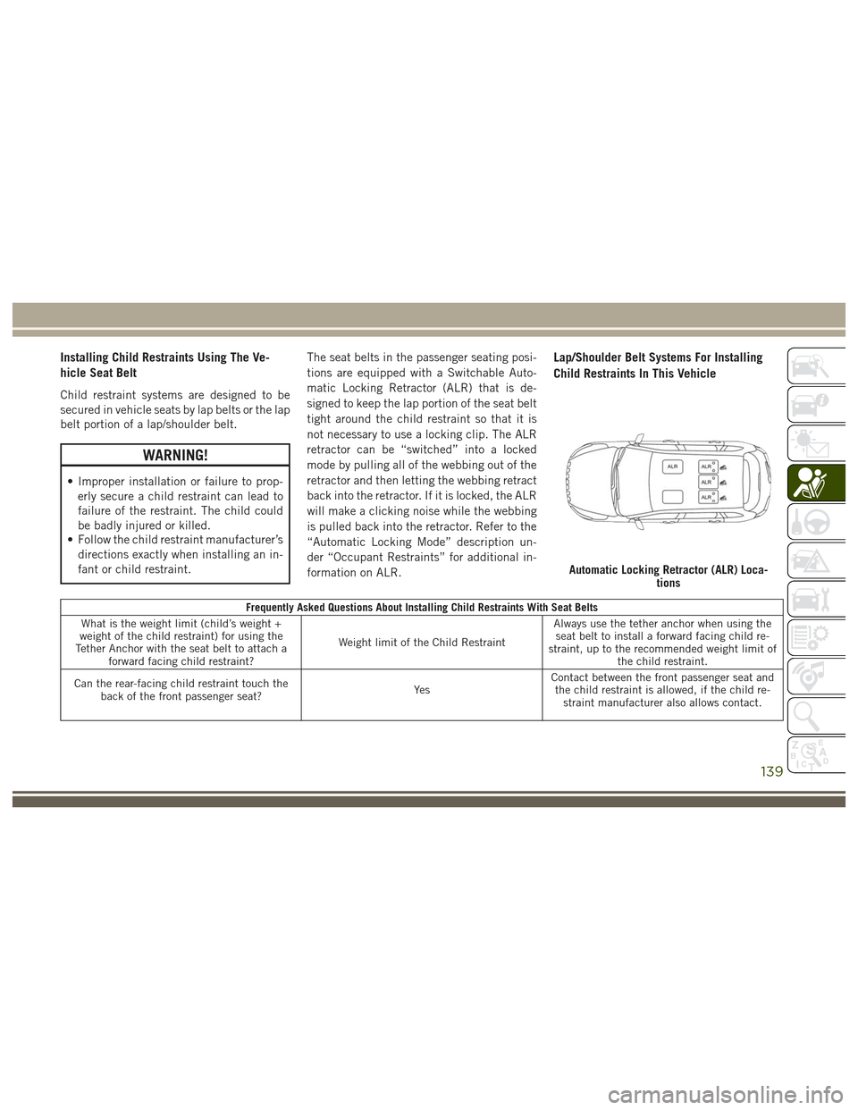
tions are equipped with a Switchable Auto-
matic Locking Retractor (ALR) that is de-
signed to keep the lap portion of the seat belt
tight around the child restraint so that it is
not necessary to use a locking clip. The ALR
retractor can be “switched” into a locked
mode by pulling all of the webbing out of the
retractor and then letting the webbing retract
back into the retractor. If it is locked, the ALR
will make a clicking noise while the webbing
is pulled back into the retractor. Refer to the
“Automatic Locking Mode” description un-
der “Occupant Restraints” for additional in-
formation on ALR.
Lap/Shoulder Belt Systems For Installing
Child Restraints In This Vehicle
Frequently Asked Questions About Installing Child Restraints With Seat Belts
What is the weight limit (child’s weight +
weight of the child restraint) for using the
Tether Anchor with the seat belt to attach a forward facing child restraint? Weight limit of the Child RestraintAlways use the tether anchor when using the
seat belt to install a forward facing child re-
straint, up to the recommended weight limit of the child restraint.
Can the rear-facing child restraint touch the back of the front passenger seat? Ye sContact between the front passenger seat and
the child restraint is allowed, if the child re- straint manufacturer also allows contact.
Automatic Locking Retractor (ALR) Loca- tions
139
Page 146 of 372
Front seat belt assemblies must be replaced
after a collision. Rear seat belt assemblies
must be replaced after a collision if they have
been damaged (i.e., bent retractor, torn web-
bing, etc.). If there is any question regarding
seat belt or retractor condition, replace the
seat belt.
Air Bag Warning Light
The Air Bag warning lightwill turn on for
four to eight seconds as a bulb check when
the ignition switch is first turned to ON/RUN.
If the light is either not on during starting,
stays on, or turns on while driving, have the
system inspected at an authorized dealer as
soon as possible. This light will illuminate
with a single chime when a fault with the Air
Bag Warning Light has been detected, it will
stay on until the fault is cleared. If the light
comes on intermittently or remains on while
driving, have an authorized dealer service the
vehicle immediately. Refer to “Occupant Re-
straint Systems” in “Safety” for further infor-
mation.
Defroster
Check operation by selecting the defrost
mode and place the blower control on high
speed. You should be able to feel the air
directed against the windshield. See your
authorized dealer for service if your defroster
is inoperable.
Floor Mat Safety Information
Always use floor mats designed to fit your
vehicle. Only use a floor mat that does not
interfere with the operation of the accelera-
tor, brake or clutch pedals. Only use a floor
mat that is securely attached using the floor
mat fasteners so it cannot slip out of position
and interfere with the accelerator, brake or
clutch pedals or impair safe operation of your
vehicle in other ways.
WARNING!
An improperly attached, damaged, folded,
or stacked floor mat, or damaged floor mat
fasteners may cause your floor mat to
interfere with the accelerator, brake, or
clutch pedals and cause a loss of vehicle
WARNING!
control. To prevent SERIOUS INJURY or
DEATH:
• ALWAYS securely attach
your floor
mat using the floor mat fasteners. DO
NOT install your floor mat upside down
or turn your floor mat over. Lightly pull to
confirm mat is secured using the floor
mat fasteners on a regular basis.
• ALWAYS REMOVE THE EXISTING
FLOOR MAT FROM THE VEHICLE
before installing any other floor mat.
NEVER install or stack an additional
floor mat on top of an existing floor mat.
• ONLY install floor mats designed to fit
your vehicle. NEVER install a floor mat
that cannot be properly attached and
secured to your vehicle. If a floor mat
needs to be replaced, only use a FCA
approved floor mat for the specific
make, model, and year of your vehicle.
• ONLY use the driver’s side floor mat on
the driver’s side floor area. To check for
interference, with the vehicle properly
parked with the engine off, fully depress
the accelerator, the brake, and the
SAFETY
144
Page 149 of 372
STARTING AND OPERATING
STARTING PROCEDURES — GASO-
LINEENGINES..............149
Normal Starting...............149
Cold Weather Operation (Below –22°F Or
−30°C) ....................150
After Starting .................150
If Engine Fails To Start ..........150
After Starting .................150
STARTING PROCEDURES — DIESEL
ENGINES................. .150
Automatic Transmission..........151
Extreme Cold Weather ...........151
Normal Starting Procedure — Keyless
Enter-N-Go ..................152
Starting Fluids ................152
STOP/START SYSTEM — IF
EQUIPPED................ .153
Automatic Mode..............153
Possible Reasons The Engine Does Not
Autostop ...................153
To Start The Engine While In Autostop
Mode .....................154 To Manually Turn Off The Stop/Start
System
....................154
To Manually Turn On The Stop/Start
System ....................155
ENGINE BREAK-IN RECOMMENDA-
TIONS................... .155
3.6L & 5.7L Engines............155
Diesel Engines ................156
SRT Engines .................156
AUTOMATIC TRANSMISSION . . .157
Ignition Park Interlock ...........158
Brake/Transmission Shift Interlock
System ....................158
Fuel Economy (ECO) Mode ........158
Eight–Speed Automatic Transmission . .159
SPORT MODE — IF EQUIPPED . .161
FOUR WHEEL DRIVE
OPERATION............... .161
Quadra-Trac I Operating Instructions/
Precautions — If Equipped........161
Quadra-Trac II Operating Instructions/
Precautions — If Equipped ........162Shift Positions
................162
Shifting Procedures .............163
Quadra-Drive II System — If Equipped .165
QUADRA-LIFT — IF EQUIPPED . .166
Description .................166
Air Suspension Modes ...........168
Instrument Cluster Display Messages . .168
Operation ..................168
SELEC-TERRAIN — IF
EQUIPPED................ .170
Selec-Terrain Mode Selection.......170
Instrument Cluster Display Messages . .171
SELEC-TRACK — IF EQUIPPED
(SRT).................... .171
Custom....................171
Active Damping System ..........172
ELECTRONIC SPEED CONTROL .172
Activation...................173
Setting A Desired Speed .........173
Varying The Speed .............173
Resume Speed ...............174
STARTING AND OPERATING
147
Page 151 of 372
STARTING PROCEDURES —
GASOLINE ENGINES
Before starting your vehicle, adjust your seat,
adjust the inside and outside mirrors, fasten
your seat belt, and if present, instruct all
other occupants to buckle their seat belts.
WARNING!
• Before exiting a vehicle, always shift theautomatic transmission into PARK and
apply the parking brake. Always make
sure the keyless ignition node is in the
“OFF” mode, remove the key fob from
the vehicle and lock the vehicle.
• Never leave children alone in a vehicle,
or with access to an unlocked vehicle.
Leaving children in a vehicle unattended
is dangerous for a number of reasons. A
child or others could be seriously or
fatally injured. Children should be
warned not to touch the parking brake,
brake pedal or the gear selector.
• Do not leave the key fob in or near the
vehicle, or in a location accessible to
children, and do not leave the ignition of
WARNING!
a vehicle equipped with Keyless Enter-
N-Go in the ACC or ON/RUN mode. A
child could operate power windows,
other controls, or move the vehicle.
• Do not leave children or animals inside
parked vehicles in hot weather. Interior
heat build-up may cause serious injury
or death.
Normal Starting
To Turn On The Engine Using The ENGINE START/
STOP Button
1. The transmission must be in PARK or NEUTRAL.
2. Press and hold the brake pedal while pushing the ENGINE START/STOP button
once.
3. The system takes over and attempts to start the vehicle. If the vehicle fails to
start, the starter will disengage automati-
cally after 10 seconds.
4. If you wish to stop the cranking of the engine prior to the engine starting, push
the button again. NOTE:
Normal starting of either a cold or a warm
engine is obtained without pumping or press-
ing the accelerator pedal.
To Turn Off The Engine Using ENGINE START/
STOP Button
1. Place the gear selector in PARK, then
push and release the ENGINE START/
STOP button.
2. The ignition will return to the OFF mode.
3. If the gear selector is not in PARK, the ENGINE START/STOP button must be
held for two seconds or three short pushes
in a row with the vehicle speed above
5 mph (8 km/h) before the engine will
shut off. The ignition will remain in the
ACC mode until the gear selector is in
PARK and the button is pushed twice to
the OFF mode. If the gear selector is not in
PARK and the ENGINE START/STOP but-
ton is pushed once, the instrument cluster
will display a “Vehicle Not In Park” mes-
sage and the engine will remain running.
Never leave a vehicle out of the PARK
position, or it could roll.
149
Page 152 of 372
NOTE:
If the ignition is left in the ACC or RUN
(engine not running) mode and the transmis-
sion is in PARK, the system will automatically
time out after 30 minutes of inactivity and
the ignition will cycle to the OFF mode.
ENGINE START/STOP Button Functions — With
Driver’s Foot OFF The Brake Pedal (In PARK Or
NEUTRAL Position)
The ENGINE START/STOP button operates
similar to an ignition switch. It has four
modes, OFF, ACC, RUN and START. To
change the ignition modes without starting
the vehicle and use the accessories follow
these steps:
• Starting with the ignition in the OFF mode,
• Push the ENGINE START/STOP buttononce to place the ignition to the ACC mode
(instrument cluster will display “ACC”),
• Push the ENGINE START/STOP button a second time to place the ignition to the
RUN mode (instrument cluster will display
“ON/RUN”), • Push the ENGINE START/STOP button a
third time to return the ignition to the OFF
mode (instrument cluster will display
“OFF”).
Cold Weather Operation (Below –22°F Or
−30°C)
To ensure reliable starting at these tempera-
tures, use of an externally powered electric
engine block heater (available from your Au-
thorized Dealer) is recommended.
After Starting
The idle speed is controlled automatically,
and it will decrease as the engine warms up.
If Engine Fails To Start
WARNING!
• Never pour fuel or other flammable liq-uid into the throttle body air inlet open-
ing in an attempt to start the vehicle.
This could result in flash fire causing
serious personal injury.
• Do not attempt to push or tow your
vehicle to get it started. Vehicles
WARNING!
equipped with an automatic transmis-
sion cannot be started this way. Un-
burned fuel could enter the catalytic
converter and once the engine has
started, ignite and damage the converter
and vehicle.
• If the vehicle has a discharged battery,
booster cables may be used to obtain a
start from a booster battery or the battery
in another vehicle. This type of start can
be dangerous if done improperly. Refer
to “Jump-Starting” in “In Case Of Emer-
gency” for further information.
After Starting
The idle speed is controlled automatically,
and it will decrease as the engine warms up.
STARTING PROCEDURES —
DIESEL ENGINES
Before starting your vehicle, adjust your seat,
both inside and outside mirrors, and fasten
your seat belts.
STARTING AND OPERATING
150
Page 153 of 372
The starter is allowed to crank for up to
30-second intervals. Waiting a few minutes
between such intervals will protect the starter
from overheating.
WARNING!
• Before exiting a vehicle, always shift theautomatic transmission into PARK and
apply the parking brake. Always make
sure the keyless ignition node is in the
“OFF” mode, remove the key fob from
the vehicle and lock the vehicle.
• Never leave children alone in a vehicle,
or with access to an unlocked vehicle.
Leaving children in a vehicle unattended
is dangerous for a number of reasons. A
child or others could be seriously or
fatally injured. Children should be
warned not to touch the parking brake,
brake pedal or the gear selector.
• Do not leave the key fob in or near the
vehicle, or in a location accessible to
children, and do not leave the ignition of
a vehicle equipped with Keyless Enter-
N-Go in the ACC or ON/RUN mode. A
WARNING!
child could operate power windows,
other controls, or move the vehicle.
• Do not leave children or animals inside
parked vehicles in hot weather. Interior
heat build-up may cause serious injury
or death.
NOTE:
Engine start up in very low ambient tempera-
ture could result in evident white smoke. This
condition will disappear as the engine warms
up.
CAUTION!
• The engine is allowed to crank as long as 30 seconds. If the engine fails to start
during this period, please wait at least
two minutes for the starter to cool before
repeating start procedure.
• If the “Water in Fuel Indicator Light”
remains on, DO NOT START engine be-
fore you drain the water from the fuel
filters to avoid engine damage. Refer to
“Draining Fuel/Water Separator Filter”
CAUTION!
in “Servicing And Maintenance” for fur-
ther information.
Automatic Transmission
Start the engine with the transmission gear
selector in the PARK position. Apply the
brake before shifting to any driving range.
Extreme Cold Weather
The engine block heater is a resistance heater
installed in the water jacket of the engine. It
requires a 110–115 Volt AC electrical outlet
with a grounded, three-wire extension cord.
Its use is recommended for environments
that routinely fall below -10°F (-23°C). It
should be used when the vehicle has not been
running overnight or longer periods and
should be plugged in two hours prior to start.
Its use is required for cold starts with tem-
peratures under -20°F (-28°C).
151