steering wheel JEEP GRAND CHEROKEE 2017 WK2 / 4.G Owner's Manual
[x] Cancel search | Manufacturer: JEEP, Model Year: 2017, Model line: GRAND CHEROKEE, Model: JEEP GRAND CHEROKEE 2017 WK2 / 4.GPages: 372
Page 124 of 372
WARNING!
Ignoring the Air Bag Warning Light in your
instrument panel could mean you won’t
have the air bag system to protect you in a
collision. If the light does not come on as a
bulb check when the ignition is first
turned on, stays on after you start the
vehicle, or if it comes on as you drive, have
an authorized dealer service the air bag
system immediately.
Redundant Air Bag Warning Light
If a fault with the Air Bag Warning Light
is detected, which could affect the Supple-
mental Restraint System (“SRS”), the Re-
dundant Air Bag Warning Light will illumi-
nate on the instrument panel. The
Redundant Air Bag Warning Light will stay on
until the fault is cleared. In addition, a single
chime will sound to alert you that the Redun-
dant Air Bag Warning Light has come on and
a fault has been detected. If the Redundant
Air Bag Warning Light comes on intermit-
tently or remains on while driving have an
authorized dealer service the vehicle imme-
diately. For additional information regarding the Re-
dundant Air Bag Warning Light, refer to
“Warning/Indicator Lights and Messages” in
“Getting to Know Your Instrument Panel”
section of this manual.
Front Air Bags
This vehicle has front air bags and lap/
shoulder belts for both the driver and front
passenger. The front air bags are a supple-
ment to the seat belt restraint systems. The
driver front air bag is mounted in the center
of the steering wheel. The passenger front air
bag is mounted in the instrument panel,
above the glove compartment. The words
“SRS AIRBAG” or “AIRBAG” are embossed
on the air bag covers.
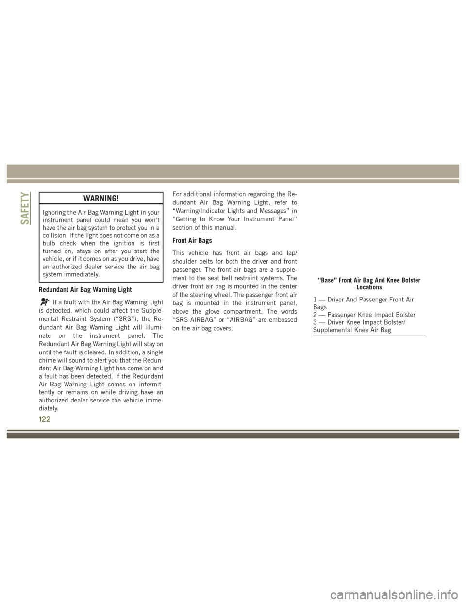
“Base” Front Air Bag And Knee Bolster
Locations
1 — Driver And Passenger Front Air
Bags
2 — Passenger Knee Impact Bolster
3 — Driver Knee Impact Bolster/
Supplemental Knee Air Bag
SAFETY
122
Page 125 of 372
WARNING!
• Being too close to the steering wheel orinstrument panel during front air bag
deployment could cause serious injury,
including death. Air bags need room to
inflate. Sit back, comfortably extending
WARNING!
your arms to reach the steering wheel or
instrument panel.
• Never place a rear-facing child restraint
in front of an air bag. A deploying pas-
senger front air bag can cause death or
serious injury to a child 12 years or
younger, including a child in a rear-
facing child restraint.
• Only use a rear-facing child restraint in a
vehicle with a rear seat.
Driver and Passenger Front Air Bag Features
The Advanced Front Air Bag system has mul-
tistage driver and front passenger air bags.
This system provides output appropriate to
the severity and type of collision as deter-
mined by the Occupant Restraint Controller
(ORC), which may receive information from
the front impact sensors (if equipped) or
other system components.
The first stage inflator is triggered immedi-
ately during an impact that requires air bag
deployment. A low energy output is used in
less severe collisions. A higher energy output
is used for more severe collisions. This vehicle may be equipped with a driver
and/or front passenger seat belt buckle
switch that detects whether the driver or front
passenger seat belt is buckled. The seat belt
buckle switch may adjust the inflation rate of
the Advanced Front Air Bags.
This vehicle may be equipped with driver
and/or front passenger seat track position
sensors that may adjust the inflation rate of
the Advanced Front Air Bags based upon seat
position.
WARNING!
• No objects should be placed over or near
the air bag on the instrument panel or
steering wheel because any such objects
could cause harm if the vehicle is in a
collision severe enough to cause the air
bag to inflate.
• Do not put anything on or around the air
bag covers or attempt to open them
manually. You may damage the air bags
and you could be injured because the air
bags may no longer be functional. The
protective covers for the air bag cushions
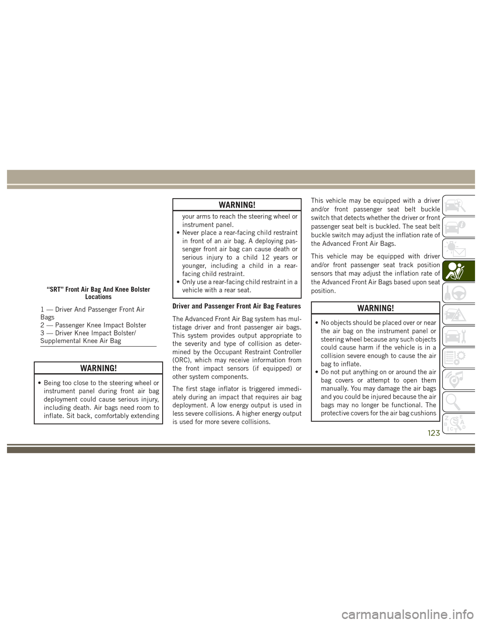
“SRT” Front Air Bag And Knee Bolster Locations
1 — Driver And Passenger Front Air
Bags
2 — Passenger Knee Impact Bolster
3 — Driver Knee Impact Bolster/
Supplemental Knee Air Bag
123
Page 126 of 372
WARNING!
are designed to open only when the air
bags are inflating.
• Relying on the air bags alone could lead
to more severe injuries in a collision. The
air bags work with your seat belt to
restrain you properly. In some collisions,
air bags won’t deploy at all. Always wear
your seat belts even though you have air
bags.
Front Air Bag Operation
Front Air Bags are designed to provide addi-
tional protection by supplementing the seat
belts. Front air bags are not expected to
reduce the risk of injury in rear, side, or
rollover collisions. The front air bags will not
deploy in all frontal collisions, including
some that may produce substantial vehicle
damage — for example, some pole collisions,
truck underrides, and angle offset collisions.
On the other hand, depending on the type
and location of impact, front air bags may
deploy in crashes with little vehicle front-end
damage but that produce a severe initial
deceleration. Because air bag sensors measure vehicle
deceleration over time, vehicle speed and
damage by themselves are not good indica-
tors of whether or not an air bag should have
deployed.
Seat belts are necessary for your protection in
all collisions, and also are needed to help
keep you in position, away from an inflating
air bag.
When the ORC detects a collision requiring
the front air bags, it signals the inflator units.
A large quantity of non-toxic gas is generated
to inflate the front air bags.
The steering wheel hub trim cover and the
upper right side of the instrument panel
separate and fold out of the way as the air
bags inflate to their full size. The front air
bags fully inflate in less time than it takes to
blink your eyes. The front air bags then
quickly deflate while helping to restrain the
driver and front passenger.
Knee Impact Bolsters
The Knee Impact Bolsters help protect the
knees of the driver and front passenger, and
position the front occupants for improved
interaction with the front air bags.
WARNING!
• Do not drill, cut, or tamper with the knee
impact bolsters in any way.
• Do not mount any accessories to the
knee impact bolsters such as alarm
lights, stereos, citizen band radios, etc.
Supplemental Driver Knee Air Bag
This vehicle is equipped with a Supplemental
Driver Knee Air Bag mounted in the instru-
ment panel below the steering column. The
Supplemental Driver Knee Air Bag provides
enhanced protection during a frontal impact
by working together with the seat belts, pre-
tensioners, and front air bags.
SAFETY
124
Page 129 of 372
NOTE:
Air bag covers may not be obvious in the
interior trim, but they will open during air bag
deployment.
Side Impacts
In side impacts, the side impact sensors aid
the ORC in determining the appropriate re-
sponse to impact events. The system is cali-
brated to deploy the Side Air Bags on the
impact side of the vehicle during impacts
that require Side Air Bag occupant protec-
tion. In side impacts, the Side Air Bags de-
ploy independently; a left side impact de-
ploys the left Side Air Bags only and a right
side impact deploys the right Side Air Bags
only.
The Side Air Bags will not deploy in all side
collisions, including some collisions at cer-
tain angles, or some side collisions that do
not impact the area of the passenger com-
partment. The Side Air Bags may deploy
during angled or offset frontal collisions
where the front air bags deploy.Rollover Events
Side Air Bags are designed to activate in
certain rollover events. The ORC determines
whether the deployment of the Side Air Bags
in a particular rollover event is appropriate,
based on the severity and type of collision.
Vehicle damage by itself is not a good indica-
tor of whether or not Side Air Bags should
have deployed.
The Side Air Bags will not deploy in all
rollover events. The rollover sensing system
determines if a rollover event may be in
progress and whether deployment is appro-
priate. In the event the vehicle experiences a
rollover or near rollover event, and deploy-
ment of the Side Air Bags is appropriate, the
rollover sensing system will also deploy the
seat belt pretensioners on both sides of the
vehicle.
The SABICs may help reduce the risk of
partial or complete ejection of vehicle occu-
pants through side windows in certain roll-
over or side impact events.The Occupant Restraint Controller (ORC)
monitors the internal circuits and intercon-
necting wiring associated with electrical Air
Bag System Components listed below:
Air Bag System Components
• Occupant Restraint Controller (ORC)
• Air Bag Warning Light
• Steering Wheel and Column
• Instrument Panel
• Knee Impact Bolsters
• Driver and Front Passenger Air Bags
• Supplemental Side Air Bags
• Supplemental Knee Air Bags
• Front and Side Impact Sensors
• Seat Belt Pretensioners
• Seat Belt Buckle Switch
127
Page 131 of 372
Enhanced Accident Response System Reset
Procedure
In order to reset the Enhanced Accident Re-
sponse System functions after an event, the
ignition switch must be changed from igni-
tion START or ON/RUN to ignition OFF. Care-
fully check the vehicle for fuel leaks in the
engine compartment and on the ground near
the engine compartment and fuel tank before
resetting the system and starting the engine.
Maintaining Your Air Bag System
WARNING!
• Modifications to any part of the air bagsystem could cause it to fail when you
need it. You could be injured if the air
bag system is not there to protect you.
Do not modify the components or wiring,
including adding any kind of badges or
stickers to the steering wheel hub trim
cover or the upper right side of the in-
strument panel. Do not modify the front
bumper, vehicle body structure, or add
aftermarket side steps or running
boards.
WARNING!
• It is dangerous to try to repair any part ofthe air bag system yourself. Be sure to
tell anyone who works on your vehicle
that it has an air bag system.
• Do not attempt to modify any part of your
air bag system. The air bag may inflate
accidentally or may not function prop-
erly if modifications are made. Take your
vehicle to an authorized dealer for any
air bag system service. If your seat, in-
cluding your trim cover and cushion,
needs to be serviced in any way (includ-
ing removal or loosening/tightening of
seat attachment bolts), take the vehicle
to your authorized dealer. Only manufac-
turer approved seat accessories may be
used. If it is necessary to modify the air
bag system for persons with disabilities,
contact your authorized dealer.
Event Data Recorder (EDR)
This vehicle is equipped with an event data
recorder (EDR). The main purpose of an EDR
is to record, in certain crash or near crash-like
situations, such as an air bag deployment or hitting a road obstacle, data that will assist in
understanding how a vehicle’s systems per-
formed. The EDR is designed to record data
related to vehicle dynamics and safety sys-
tems for a short period of time, typically
30 seconds or less. The EDR in this vehicle is
designed to record such data as:
• How various systems in your vehicle were
operating;
• Whether or not the driver and passenger safety belts were buckled/fastened;
• How far (if at all) the driver was depressing the accelerator and/or brake pedal; and,
• How fast the vehicle was traveling.
• These data can help provide a better un- derstanding of the circumstances in which
crashes and injuries occur.
129
Page 147 of 372
WARNING!
clutch pedal (if present) to check for
interference. If your floor mat interferes
with the operation of any pedal, or is not
secure to the floor, remove the floor mat
from the vehicle and place the floor mat
in your trunk.
• ONLY use the passenger’s side floor mat
on the passenger’s side floor area.
• ALWAYS make sure objects cannot fall
or slide into the driver’s side floor area
when the vehicle is moving. Objects can
become trapped under accelerator,
brake, or clutch pedals and could cause
a loss of vehicle control.
• NEVER place any objects under the floor
mat (e.g., towels, keys, etc.). These ob-
jects could change the position of the
floor mat and may cause interference
with the accelerator, brake, or clutch
pedals.
• If the vehicle carpet has been removed
and re-installed, always properly attach
WARNING!
carpet to the floor and check the floor
mat fasteners are secure to the vehicle
carpet. Fully depress each pedal to
check for interference with the accelera-
tor, brake, or clutch pedals then re-
install the floor mats.
• It is recommended to only use mild soap
and water to clean your floor mats. After
cleaning, always check your floor mat
has been properly installed and is se-
cured to your vehicle using the floor mat
fasteners by lightly pulling mat.
Periodic Safety Checks You Should Make
Outside The Vehicle
Tires
Examine tires for excessive tread wear and
uneven wear patterns. Check for stones,
nails, glass, or other objects lodged in the
tread or sidewall. Inspect the tread for cuts and cracks. Inspect sidewalls for cuts,
cracks, and bulges. Check the wheel nuts for
tightness. Check the tires (including spare)
for proper cold inflation pressure.
Lights
Have someone observe the operation of brake
lights and exterior lights while you work the
controls. Check turn signal and high beam
indicator lights on the instrument panel.
Door Latches
Check for proper closing, latching, and lock-
ing.
Fluid Leaks
Check area under vehicle after overnight
parking for fuel, engine coolant, oil, or other
fluid leaks. Also, if gasoline fumes are de-
tected or if fuel, power steering fluid (if
equipped), or brake fluid leaks are sus-
pected. The cause should be located and
corrected immediately.
145
Page 162 of 372
AutoStick
AutoStick is a driver-interactive transmission
feature providing manual shift control, giving
you more control of the vehicle. AutoStick
allows you to maximize engine braking, elimi-
nate undesirable upshifts and downshifts,
and improve overall vehicle performance.
This system can also provide you with more
control during passing, city driving, cold slip-
pery conditions, mountain driving, trailer
towing, and many other situations.
Operation
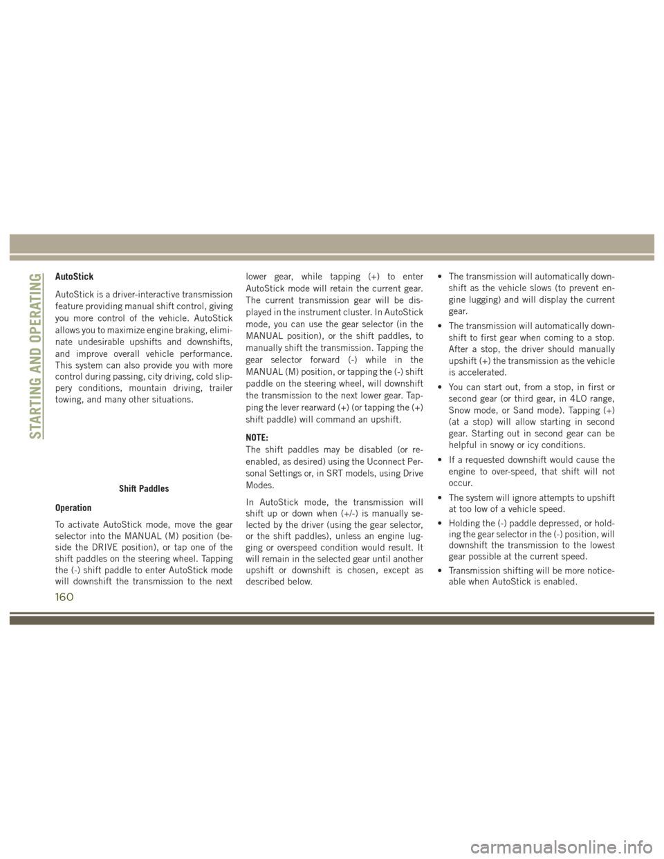
To activate AutoStick mode, move the gear
selector into the MANUAL (M) position (be-
side the DRIVE position), or tap one of the
shift paddles on the steering wheel. Tapping
the (-) shift paddle to enter AutoStick mode
will downshift the transmission to the nextlower gear, while tapping (+) to enter
AutoStick mode will retain the current gear.
The current transmission gear will be dis-
played in the instrument cluster. In AutoStick
mode, you can use the gear selector (in the
MANUAL position), or the shift paddles, to
manually shift the transmission. Tapping the
gear selector forward (-) while in the
MANUAL (M) position, or tapping the (-) shift
paddle on the steering wheel, will downshift
the transmission to the next lower gear. Tap-
ping the lever rearward (+) (or tapping the (+)
shift paddle) will command an upshift.
NOTE:
The shift paddles may be disabled (or re-
enabled, as desired) using the Uconnect Per-
sonal Settings or, in SRT models, using Drive
Modes.
In AutoStick mode, the transmission will
shift up or down when (+/-) is manually se-
lected by the driver (using the gear selector,
or the shift paddles), unless an engine lug-
ging or overspeed condition would result. It
will remain in the selected gear until another
upshift or downshift is chosen, except as
described below. • The transmission will automatically down-
shift as the vehicle slows (to prevent en-
gine lugging) and will display the current
gear.
• The transmission will automatically down- shift to first gear when coming to a stop.
After a stop, the driver should manually
upshift (+) the transmission as the vehicle
is accelerated.
• You can start out, from a stop, in first or second gear (or third gear, in 4LO range,
Snow mode, or Sand mode). Tapping (+)
(at a stop) will allow starting in second
gear. Starting out in second gear can be
helpful in snowy or icy conditions.
• If a requested downshift would cause the engine to over-speed, that shift will not
occur.
• The system will ignore attempts to upshift at too low of a vehicle speed.
• Holding the (-) paddle depressed, or hold- ing the gear selector in the (-) position, will
downshift the transmission to the lowest
gear possible at the current speed.
• Transmission shifting will be more notice- able when AutoStick is enabled.
Shift Paddles
STARTING AND OPERATING
160
Page 163 of 372
• The system may revert to automatic shiftmode if a fault or overheat condition is
detected.
NOTE:
When Selec-Speed or Hill Descent Control is
enabled, AutoStick is not active.
To disengage AutoStick, return the gear se-
lector to the DRIVE position, or press and
hold the (+) shift paddle (if the gear selector
is already in DRIVE) until "D" is once again
indicated in the instrument cluster. You can
shift in or out of AutoStick at any time with-
out taking your foot off the accelerator pedal.
WARNING!
Do not downshift for additional engine
braking on a slippery surface. The drive
wheels could lose their grip and the ve-
hicle could skid, causing a collision or
personal injury.
SPORT MODE — IF
EQUIPPED
Your vehicle is equipped with a Sport Mode
feature. This mode is a configuration set up
for typical enthusiast driving. The engine,
transmission, and steering systems are all set
to their SPORT settings. Sport Mode will
provide improved throttle response and modi-
fied shifting for an enhanced driving experi-
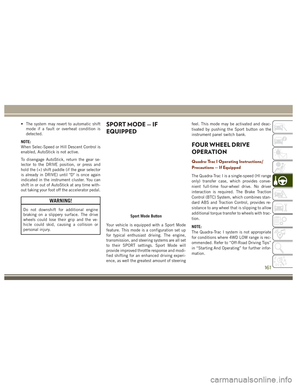
ence, as well the greatest amount of steering feel. This mode may be activated and deac-
tivated by pushing the Sport button on the
instrument panel switch bank.
FOUR WHEEL DRIVE
OPERATION
Quadra-Trac I Operating Instructions/
Precautions — If Equipped
The Quadra-Trac I is a single-speed (HI range
only) transfer case, which provides conve-
nient full-time four-wheel drive. No driver
interaction is required. The Brake Traction
Control (BTC) System, which combines stan-
dard ABS and Traction Control, provides re-
sistance to any wheel that is slipping to allow
additional torque transfer to wheels with trac-
tion.
NOTE:
The Quadra-Trac I system is not appropriate
for conditions where 4WD LOW range is rec-
ommended. Refer to “Off-Road Driving Tips”
in “Starting And Operating” for further infor-
mation.
Sport Mode Button
161
Page 172 of 372
SELEC-TERRAIN — IF
EQUIPPED
Selec-Terrain Mode Selection
Selec-Terrain combines the capabilities of
the vehicle control systems, along with driver
input, to provide the best performance for all
terrains. Selec-Terrain consists of the following posi-
tions:
•
Snow – Tuning set for additional stability
in inclement weather. Use on and off road
on loose traction surfaces such as snow.
When in Snow mode (depending on cer-
tain operating conditions), the transmis-
sion may use second gear (rather than first
gear) during launches, to minimize wheel
slippage. If equipped with air suspension,
the default ride height for Snow is Normal
Ride Height (NRH).
• Auto – Fully automatic full time four-wheel
drive operation can be used on and off
road. Balances traction with seamless
steering feel to provide improved handling
and acceleration over two-wheel drive ve-
hicles. If equipped with air suspension,
the level will change to Normal Ride
Height (NRH).
• Sand – Off road calibration for use on low
traction surfaces such as sand or wet
grass. Driveline is maximized for traction.
Some binding may be felt on less forgiving
surfaces. The electronic brake controls are
set to limit traction control management of throttle and wheel spin. If equipped
with air suspension, the default ride
height for Sand is Normal Ride Height
(NRH).
• Mud – Off road calibration for use on low
traction surfaces such as mud. Driveline is
maximized for traction. Some binding may
be felt on less forgiving surfaces. The
electronic brake controls are set to limit
traction control management of throttle
and wheel spin. If equipped with air sus-
pension, the level will change to Off Road
1.
• Rock – Off road calibration only available
in 4WD Low range. The vehicle is raised (if
equipped with Air Suspension) for im-
proved ground clearance. Traction based
tuning with improved steer-ability for use
on high traction off-road surfaces. Use for
low speed obstacles such as large rocks,
deep ruts, etc. If equipped with air sus-
pension, the vehicle level will change to
Off-Road 2. If the Selec-Terrain switch is
in ROCK mode, and the transfer case is
switched from 4WD Low to 4WD High, the
Selec-Terrain system will return to AUTO.
Selec-Terrain Switch
STARTING AND OPERATING
170
Page 173 of 372
NOTE:
Activate the Hill Descent Control or Selec
Speed Control for steep downhill control. See
“Electronic Brake Control System” in this
section for further information.
Instrument Cluster Display Messages
When the appropriate conditions exist, a
message will appear in the instrument clus-
ter. Refer to “Instrument Cluster Display” in
“Getting To Know Your Instrument Panel” for
further information.
SELEC-TRACK — IF
EQUIPPED (SRT)
Description
Selec-Track combines the capabilities of the
vehicle control systems, along with driver
input, to provide the best performance for all
terrains.
Rotate the Selec-Track knob to select the
desired mode.Refer to “Drive Modes” in the “Multimedia”
section in your Owner’s Manual at
www.jeep.com/en/owners/manuals/ for fur-
ther information.
Selec-Track consists of the following posi-
tions:
•
Sport – Dry weather, on-road calibration.
Performance based tuning that provides a
rear wheel drive feel but with improved
handling and acceleration over a two-
wheel drive vehicle. This feature will reset
to AUTO on an ignition cycle.
• Snow – Tuning set for additional stability in
inclement weather. Use on and off road on
loose traction surfaces such as snow. This
feature will reset to AUTO upon an ignition
cycle. •
Auto – Fully automatic full time four-wheel
drive operation can be used on and off
road. Balances traction with seamless
steering feel to provide improved handling
and acceleration over two-wheel drive ve-
hicles.
• Track – Track road calibration for use on
high traction surfaces. Driveline is maxi-
mized for traction. Some binding may be
felt on less forgiving surfaces. This feature
will reset to AUTO on an ignition cycle.
• To w – Use this mode for towing and haul-
ing heavy loads. Vehicle suspension will go
to sport mode. Trailer sway control is en-
abled in the ESC system. This feature will
reset to AUTO upon an ignition cycle.
Custom
This mode allows the driver to create a cus-
tom vehicle configuration that is saved for
quick selection of favorite settings. The sys-
tem will return to AUTO mode when the
ignition switch is cycled from RUN to OFF to
RUN, if this mode is selected. While in Cus-
tom Mode the Stability, Transmission, Steer-
Selec-Track Switch
171