lock JEEP GRAND CHEROKEE 2017 WK2 / 4.G Manual PDF
[x] Cancel search | Manufacturer: JEEP, Model Year: 2017, Model line: GRAND CHEROKEE, Model: JEEP GRAND CHEROKEE 2017 WK2 / 4.GPages: 372
Page 221 of 372
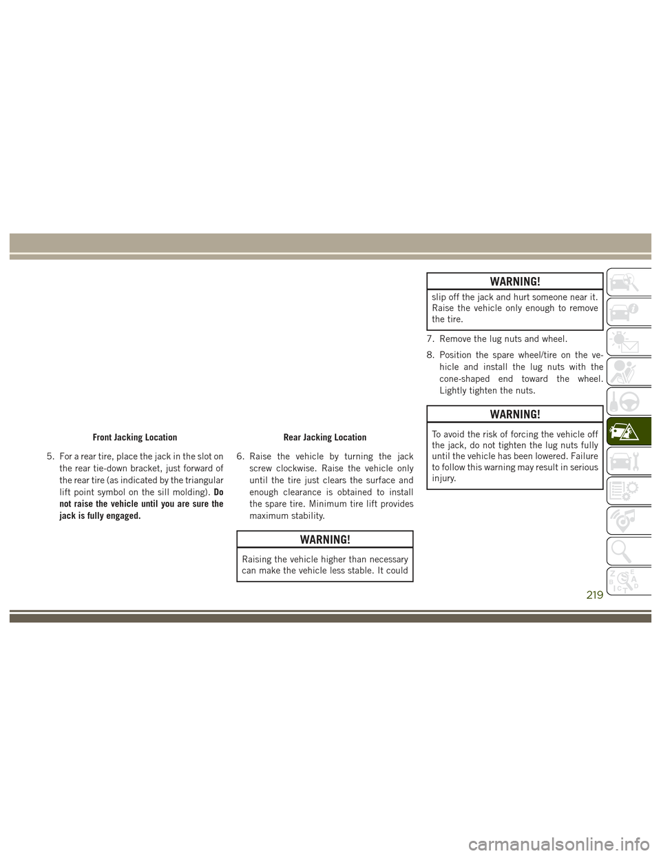
5. For a rear tire, place the jack in the slot onthe rear tie-down bracket, just forward of
the rear tire (as indicated by the triangular
lift point symbol on the sill molding). Do
not raise the vehicle until you are sure the
jack is fully engaged. 6. Raise the vehicle by turning the jack
screw clockwise. Raise the vehicle only
until the tire just clears the surface and
enough clearance is obtained to install
the spare tire. Minimum tire lift provides
maximum stability.
WARNING!
Raising the vehicle higher than necessary
can make the vehicle less stable. It could
WARNING!
slip off the jack and hurt someone near it.
Raise the vehicle only enough to remove
the tire.
7. Remove the lug nuts and wheel.
8. Position the spare wheel/tire on the ve- hicle and install the lug nuts with the
cone-shaped end toward the wheel.
Lightly tighten the nuts.
WARNING!
To avoid the risk of forcing the vehicle off
the jack, do not tighten the lug nuts fully
until the vehicle has been lowered. Failure
to follow this warning may result in serious
injury.Front Jacking LocationRear Jacking Location
219
Page 222 of 372
CAUTION!
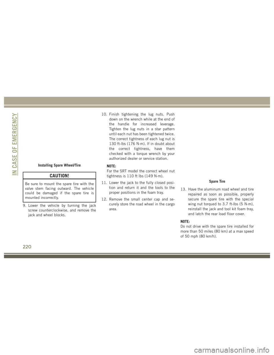
Be sure to mount the spare tire with the
valve stem facing outward. The vehicle
could be damaged if the spare tire is
mounted incorrectly.
9. Lower the vehicle by turning the jack screw counterclockwise, and remove the
jack and wheel blocks. 10. Finish tightening the lug nuts. Push
down on the wrench while at the end of
the handle for increased leverage.
Tighten the lug nuts in a star pattern
until each nut has been tightened twice.
The correct tightness of each lug nut is
130 ft-lbs (176 N·m). If in doubt about
the correct tightness, have them
checked with a torque wrench by your
authorized dealer or service station.
NOTE:
For the SRT model the correct wheel nut
tightness is 110 ft lbs (149 N·m).
11. Lower the jack to the fully closed posi- tion and return it and the tools to the
proper positions in the foam tray.
12. Remove the small center cap and se- curely store the road wheel in the cargo
area. 13. Have the aluminum road wheel and tire
repaired as soon as possible, properly
secure the spare tire with the special
wing nut torqued to 3.7 ft-lbs (5 N·m),
reinstall the jack and tool kit foam tray,
and latch the rear load floor cover.
NOTE:
Do not drive with the spare tire installed for
more than 50 miles (80 km) at a max speed
of 50 mph (80 km/h).
Installing Spare Wheel/Tire
Spare Tire
IN CASE OF EMERGENCY
220
Page 223 of 372
WARNING!
A loose tire or jack thrown forward in a
collision or hard stop could endanger the
occupants of the vehicle. Always stow the
jack parts and the spare tire in the places
provided. Have the deflated (flat) tire re-
paired or replaced immediately.
Changing Procedure
1. Mount the road tire on the axle.
2. Install the remaining lug nuts with thecone shaped end of the nut toward the
wheel. Lightly tighten the lug nuts.
WARNING!
To avoid the risk of forcing the vehicle off
the jack, do not tighten the lug nuts fully
until the vehicle has been lowered. Failure
to follow this warning may result in per-
sonal injury.
3. Lower the vehicle to the ground by turning the jack handle counterclockwise.
4. Finish tightening the lug nuts. Push down on the wrench while at the end of the handle for increased leverage. Tighten the
lug nuts in a star pattern until each nut
has been tightened twice. The correct
tightness of each lug nut is 130 ft-lbs
(176 N·m). If in doubt about the correct
tightness, have them checked with a
torque wrench by your authorized dealer
or service station.
NOTE:
For the SRT model the correct wheel nut
tightness is 110 ft lbs (149 N·m).
5. After 25 miles (40 km) check the lug nut torque with a torque wrench to ensure that
all lug nuts are properly seated against the
wheel.JUMP-STARTING
If your vehicle has a discharged battery it can
be jump-started using a set of jumper cables
and a battery in another vehicle or by using a
portable battery booster pack. Jump-starting
can be dangerous if done improperly so
please follow the procedures in this section
carefully.
WARNING!
Do not attempt jump-starting if the battery
is frozen. It could rupture or explode and
cause personal injury.
CAUTION!
Do not use a portable battery booster pack
or any other booster source with a system
voltage greater than 12 Volts or damage to
the battery, starter motor, alternator or
electrical system may occur.
NOTE:
When using a portable battery booster pack
follow the manufacturer's operating instruc-
tions and precautions.
Preparations For Jump-Starting
The battery in your vehicle is located under
the passenger's front seat. There are remote
locations located under the hood to assist in
jump-starting.
221
Page 224 of 372
WARNING!
• Take care to avoid the radiator coolingfan whenever the hood is raised. It can
start anytime the ignition switch is ON.
You can be injured by moving fan
blades.
WARNING!
• Remove any metal jewelry such as rings,watch bands and bracelets that could
make an inadvertent electrical contact.
You could be seriously injured.
• Batteries contain sulfuric acid that can
burn your skin or eyes and generate
hydrogen gas which is flammable and
explosive. Keep open flames or sparks
away from the battery.
NOTE:
Be sure that the disconnected ends of the
cables do not touch while still connected to
the either vehicle.
1. Set the parking brake, shift the automatic transmission into PARK and turn the igni-
tion to LOCK.
2. Turn off the heater, radio, and all unnec- essary electrical accessories.
3. Remove the protective cover over the re- mote positive (+)battery post. Pull up-
ward on the cover to remove it. 4. If using another vehicle to jump-start the
battery, park the vehicle within the
jumper cables reach, set the parking
brake and make sure the ignition is OFF.
WARNING!
Do not allow vehicles to touch each other
as this could establish a ground connec-
tion and personal injury could result.
Jump-Starting Procedure
WARNING!
Failure to follow this jump-starting proce-
dure could result in personal injury or
property damage due to battery explosion.
CAUTION!
Failure to follow these procedures could
result in damage to the charging system of
the booster vehicle or the discharged ve-
hicle.
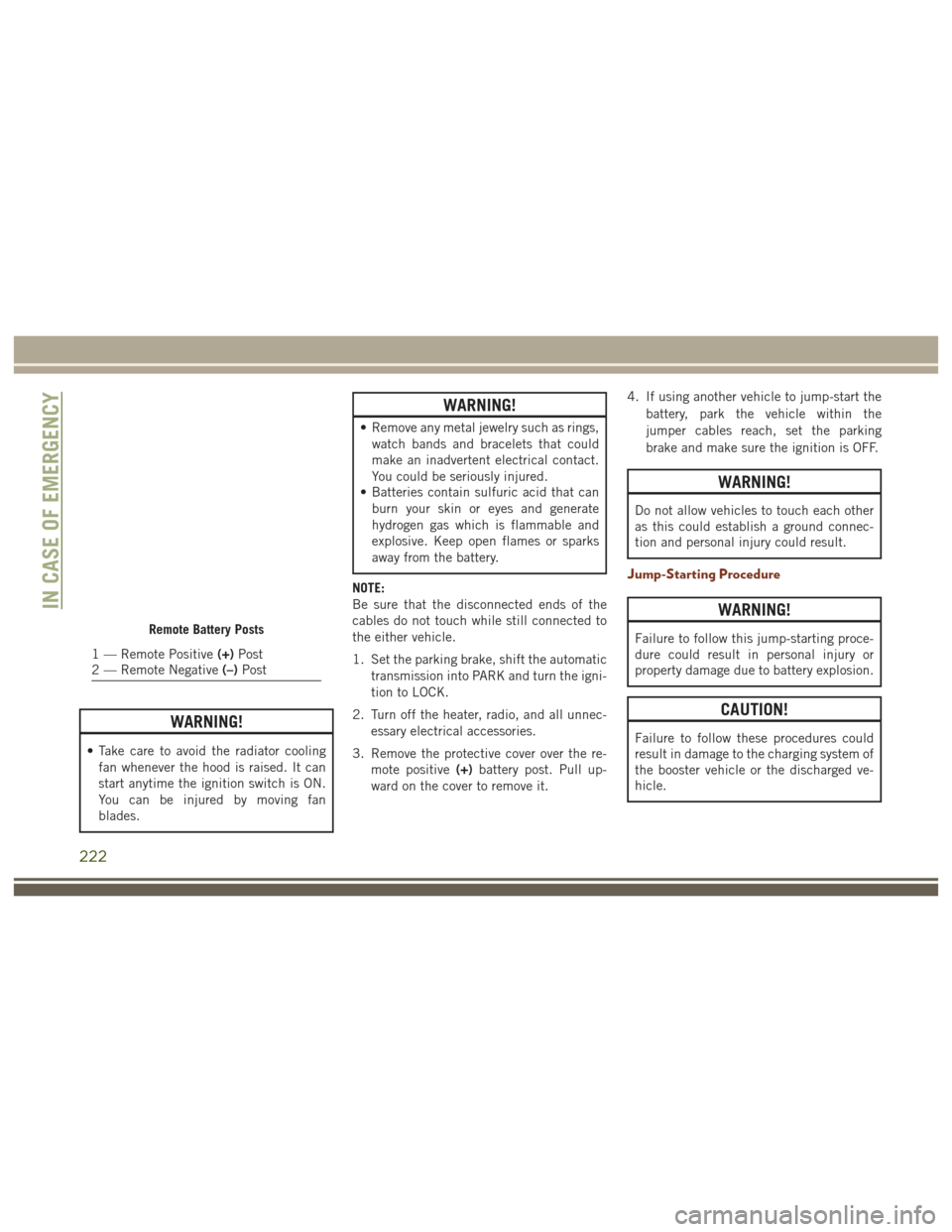
Remote Battery Posts
1 — Remote Positive (+)Post
2 — Remote Negative (–)Post
IN CASE OF EMERGENCY
222
Page 227 of 372
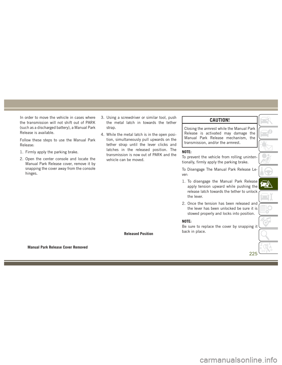
In order to move the vehicle in cases where
the transmission will not shift out of PARK
(such as a discharged battery), a Manual Park
Release is available.
Follow these steps to use the Manual Park
Release:
1. Firmly apply the parking brake.
2. Open the center console and locate theManual Park Release cover, remove it by
snapping the cover away from the console
hinges. 3. Using a screwdriver or similar tool, push
the metal latch in towards the tether
strap.
4. While the metal latch is in the open posi- tion, simultaneously pull upwards on the
tether strap until the lever clicks and
latches in the released position. The
transmission is now out of PARK and the
vehicle can be moved.CAUTION!
Closing the armrest while the Manual Park
Release is activated may damage the
Manual Park Release mechanism, the
transmission, and/or the armrest.
NOTE:
To prevent the vehicle from rolling uninten-
tionally, firmly apply the parking brake.
To Disengage The Manual Park Release Le-
ver:
1. To disengage the Manual Park Release apply tension upward while pushing the
release latch towards the tether to unlock
the lever.
2. Once the tension has been released and the lever has been unlocked be sure it is
stowed properly and locks into position.
NOTE:
Be sure to replace the cover by snapping it
back in place.
Manual Park Release Cover Removed
Released Position
225
Page 228 of 372
FREEING A STUCK VEHICLE
If your vehicle becomes stuck in mud, sand
or snow, it can often be moved using a rock-
ing motion. Turn the steering wheel right and
left to clear the area around the front wheels.
Push and hold the lock button on the gear
selector. Then shift back and forth between
DRIVE and REVERSE while gently pressing
the accelerator.
NOTE:
Shifts between DRIVE and REVERSE can
only be achieved at wheel speeds of 5 mph
(8 km/h) or less. Whenever the transmission
remains in NEUTRAL for more than two sec-
onds, you must press the brake pedal to
engage DRIVE or REVERSE.
Use the least amount of accelerator pedal
pressure that will maintain the rocking mo-
tion without spinning the wheels or racing the
engine.NOTE:
Push the "ESC Off" switch (if necessary), to
place the Electronic Stability Control (ESC)
system in "Partial Off" mode, before rocking
the vehicle. Refer to “Electronic Brake Con-
trol” in “Safety” in the Owners Manual at
www.jeep.com/en/owners/manuals/ for fur-
ther information. Once the vehicle has been
freed, push the "ESC Off" switch again to
restore "ESC On" mode.
WARNING!
Fast spinning tires can be dangerous.
Forces generated by excessive wheel
speeds may cause damage, or even failure,
of the axle and tires. A tire could explode
and injure someone. Do not spin your
vehicle's wheels faster than 30 mph
(48 km/h) or for longer than 30 seconds
continuously without stopping when you
are stuck and do not let anyone near a
spinning wheel, no matter what the speed.
CAUTION!
• Racing the engine or spinning the
wheels may lead to transmission over-
heating and failure. Allow the engine to
idle with the transmission in NEUTRAL
for at least one minute after every five
rocking-motion cycles. This will mini-
mize overheating and reduce the risk of
transmission failure during prolonged
efforts to free a stuck vehicle.
• When “rocking” a stuck vehicle by shift-
ing between DRIVE and REVERSE, do
not spin the wheels faster than 15 mph
(24 km/h), or drivetrain damage may
result.
• Revving the engine or spinning the
wheels too fast may lead to transmission
overheating and failure. It can also dam-
age the tires. Do not spin the wheels
above 30 mph (48 km/h) while in gear
(no transmission shifting occurring).
IN CASE OF EMERGENCY
226
Page 256 of 372
The wiper blades and wiper arms should be
inspected periodically, not just when wiper
performance problems are experienced. This
inspection should include the following
points:
• Wear Or Uneven Edges
• Foreign Material
• Hardening Or Cracking
• Deformation Or Fatigue
If a wiper blade or wiper arm is damaged,
replace the affected wiper arm or blade with
a new unit. Do not attempt to repair a wiper
arm or blade that is damaged.
Front Wiper Blade Removal/Installation
CAUTION!
Do not allow the wiper arm to spring back
against the glass without the wiper blade
in place or the glass may be damaged.
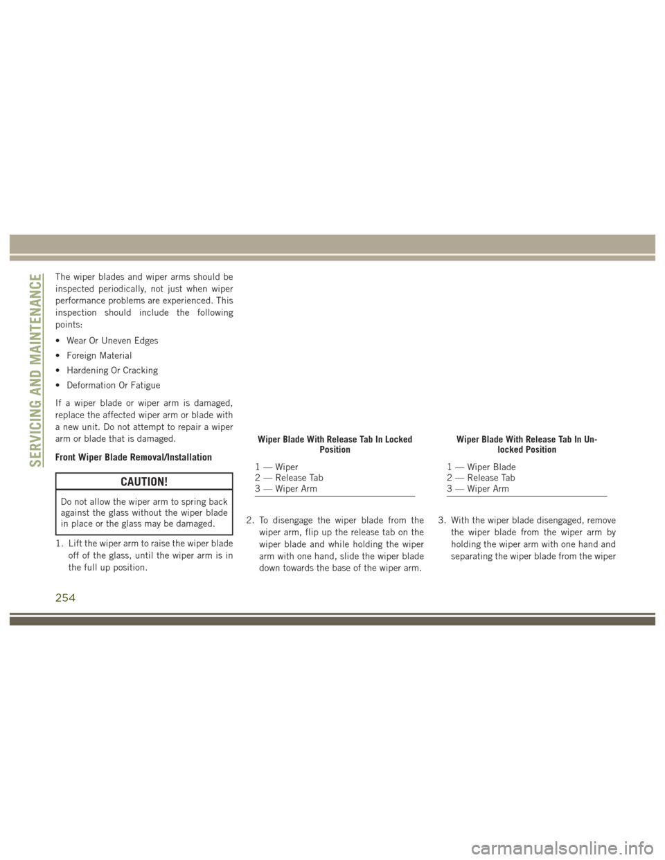
1. Lift the wiper arm to raise the wiper blade off of the glass, until the wiper arm is in
the full up position. 2. To disengage the wiper blade from the
wiper arm, flip up the release tab on the
wiper blade and while holding the wiper
arm with one hand, slide the wiper blade
down towards the base of the wiper arm. 3. With the wiper blade disengaged, remove
the wiper blade from the wiper arm by
holding the wiper arm with one hand and
separating the wiper blade from the wiper
Wiper Blade With Release Tab In Locked Position
1 — Wiper
2 — Release Tab
3 — Wiper Arm
Wiper Blade With Release Tab In Un-locked Position
1 — Wiper Blade
2 — Release Tab
3 — Wiper ArmSERVICING AND MAINTENANCE
254
Page 257 of 372
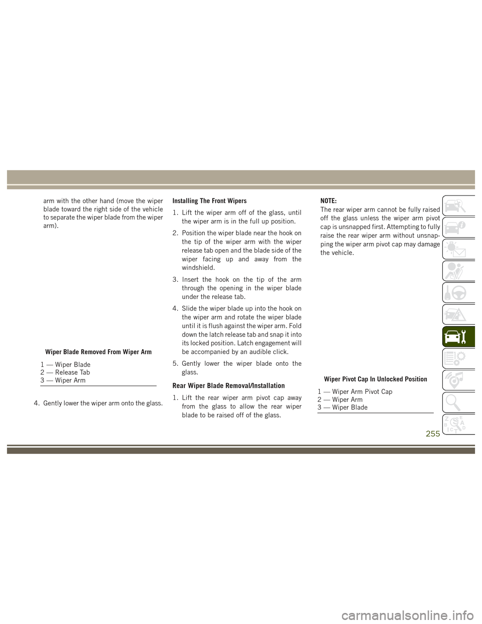
arm with the other hand (move the wiper
blade toward the right side of the vehicle
to separate the wiper blade from the wiper
arm).
4. Gently lower the wiper arm onto the glass. Installing The Front Wipers
1. Lift the wiper arm off of the glass, until
the wiper arm is in the full up position.
2. Position the wiper blade near the hook on the tip of the wiper arm with the wiper
release tab open and the blade side of the
wiper facing up and away from the
windshield.
3. Insert the hook on the tip of the arm through the opening in the wiper blade
under the release tab.
4. Slide the wiper blade up into the hook on the wiper arm and rotate the wiper blade
until it is flush against the wiper arm. Fold
down the latch release tab and snap it into
its locked position. Latch engagement will
be accompanied by an audible click.
5. Gently lower the wiper blade onto the glass.
Rear Wiper Blade Removal/Installation
1. Lift the rear wiper arm pivot cap awayfrom the glass to allow the rear wiper
blade to be raised off of the glass. NOTE:
The rear wiper arm cannot be fully raised
off the glass unless the wiper arm pivot
cap is unsnapped first. Attempting to fully
raise the rear wiper arm without unsnap-
ping the wiper arm pivot cap may damage
the vehicle.
Wiper Blade Removed From Wiper Arm
1 — Wiper Blade
2 — Release Tab
3 — Wiper Arm
Wiper Pivot Cap In Unlocked Position
1 — Wiper Arm Pivot Cap
2 — Wiper Arm
3 — Wiper Blade
255
Page 287 of 372
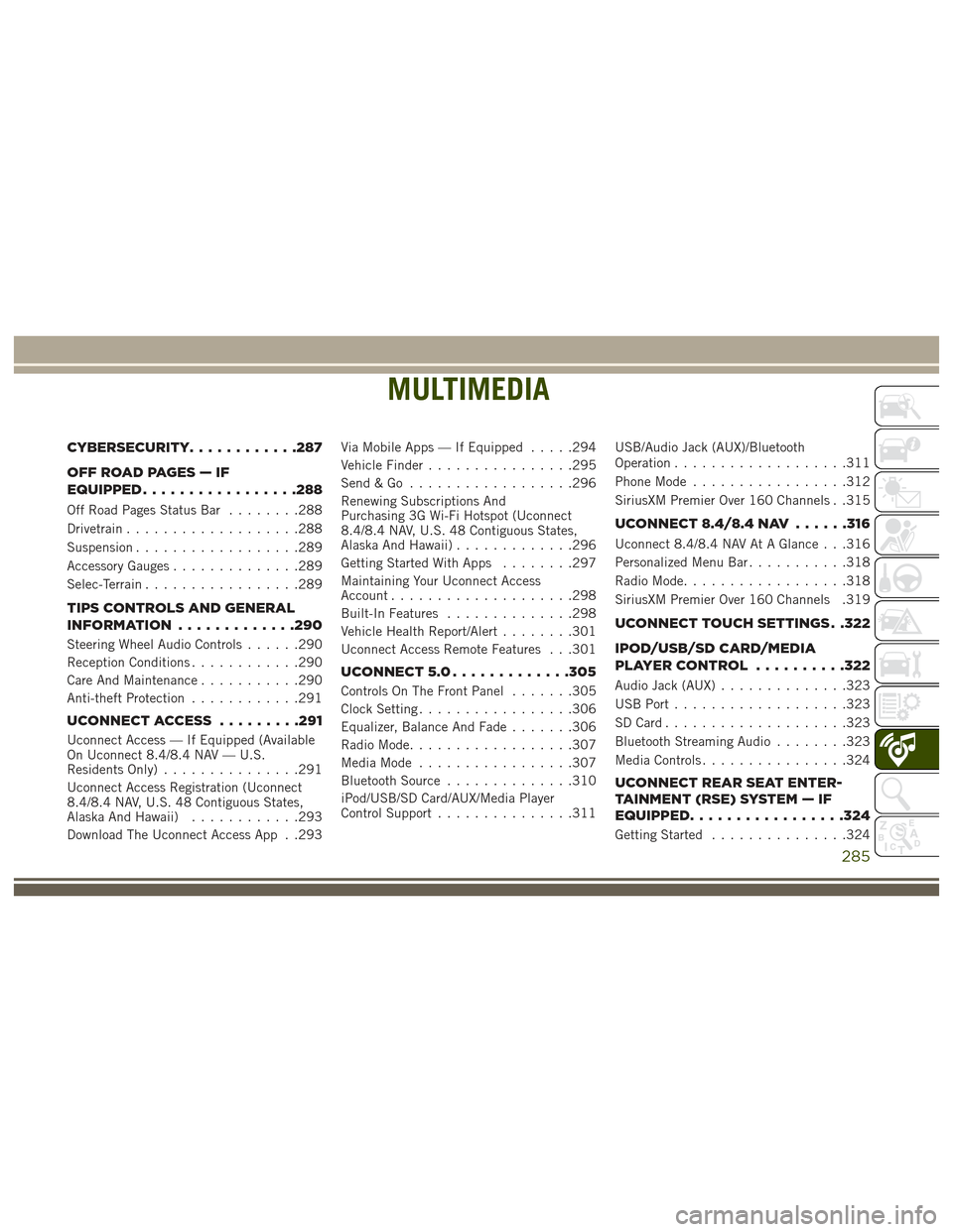
MULTIMEDIA
CYBERSECURITY............287
OFFROADPAGES—IF
EQUIPPED................ .288
Off Road Pages Status Bar........288
Drivetrain ...................288
Suspension ..................289
Accessory Gauges ..............289
Selec-Terrain .................289
TIPS CONTROLS AND GENERAL
INFORMATION ............ .290
Steering Wheel Audio Controls ......290
Reception Conditions ............290
Care And Maintenance ...........290
Anti-theft Protection ............291
UCONNECT ACCESS .........291
Uconnect Access — If Equipped (Available
On Uconnect 8.4/8.4 NAV — U.S.
Residents Only)...............291
Uconnect Access Registration (Uconnect
8.4/8.4 NAV, U.S. 48 Contiguous States,
Alaska And Hawaii) ............293
Download The Uconnect Access App . .293 Via Mobile Apps — If Equipped
.....294
Vehicle Finder ................295
Send&Go ..................296
Renewing Subscriptions And
Purchasing 3G Wi-Fi Hotspot (Uconnect
8.4/8.4 NAV, U.S. 48 Contiguous States,
Alaska And Hawaii) .............296
Getting Started With Apps ........297
Maintaining Your Uconnect Access
Account ....................298
Built-In Features ..............298
Vehicle Health Report/Alert ........301
Uconnect Access Remote Features . . .301
UCONNECT 5.0 .............305
Controls On The Front Panel .......305
Clock Setting .................306
Equalizer, Balance And Fade .......306
Radio Mode ..................307
Media Mode .................307
Bluetooth Source ..............310
iPod/USB/SD Card/AUX/Media Player
Control Support ...............311 USB/Audio Jack (AUX)/Bluetooth
Operation
...................311
Phone Mode .................312
SiriusXM Premier Over 160 Channels . .315
UCONNECT 8.4/8.4 NAV ......316
Uconnect 8.4/8.4 NAV At A Glance . . .316
Personalized Menu Bar...........318
Radio Mode ..................318
SiriusXM Premier Over 160 Channels .319
UCONNECT TOUCH SETTINGS . .322
IPOD/USB/SD CARD/MEDIA
PLAYERCONTROL ..........322
Audio Jack (AUX) ..............323
USB Port ...................323
SD Card ....................323
Bluetooth Streaming Audio ........323
Media Controls ................324
UCONNECT REAR SEAT ENTER-
TAINMENT (RSE) SYSTEM — IF
EQUIPPED................ .324
Getting Started...............324
MULTIMEDIA
285
Page 293 of 372
• Prevent any liquid from entering the sys-tem: this could damage it beyond repair.
Anti-theft Protection
The system is equipped with an anti-theft
protection system based on the exchange of
information with the electronic control unit
(Body Computer) on the vehicle.
This guarantees maximum safety and pre-
vents the secret code from being entered
after the power supply has been discon-
nected.
If the check has a positive outcome, the
system will start to operate, whereas if the
comparison codes are not the same or if the
electronic control unit (Body Computer) is
replaced, the system will ask the user to enter
the secret code according to the procedure
described in the paragraph below.
Entering The Secret Code
When the system is switched on, if the code is
requested, the display will show "Please enter
Anti-Theft Code" followed by the screen
showing a keypad to enter the secret code. The secret code has four numbers from 0 to
9: to insert the code numbers, rotate the
BROWSE/ENTER dial and press to confirm.
After entering the fourth number the system
will start functioning.
If an incorrect code is entered, the system
displays "Incorrect Code" to notify the user of
the need to enter the correct code.
After the 3 available attempts to enter the
code, the system displays "Incorrect Code.
Radio locked. Wait for 30 minutes". After the
text has disappeared it is possible to start the
code entering procedure again.
Vehicle Radio Passport
This document certifies ownership of the sys-
tem. The vehicle radio passport shows the
system model, serial number and secret
code.
In case you lose the radio passport, please go
to Jeep Assistance Network with an ID and
the car papers.
Keep the vehicle radio passport in a safe place
so that you can give the information to the
relevant authorities if the system is stolen.
UCONNECT ACCESS
Uconnect Access — If Equipped (Available
On Uconnect 8.4/8.4 NAV — U.S.
Residents Only)
WARNING!
ALWAYS drive safely with your hands on
the wheel. You have full responsibility and
assume all risks related to the use of the
Uconnect features and applications in this
vehicle. Only use Uconnect when it is safe
to do so. Failure to do so may result in an
accident involving serious injury or death.
WARNING!
ALWAYS obey traffic laws and pay atten-
tion to the road. Some Uconnect Access
services, including 9-1-1 and Assist, will
NOT work without an operable 1X (voice/
data) or 3G (data) network connection.
NOTE:
Your vehicle may be transmitting data as
authorized by the subscriber.
291